
Spider J

Spider J

Home Forums Scratch build Spider J

  • This topic is empty.
Viewing 25 posts - 151 through 175 (of 201 total)
  • Author
    Posts
  • #75421
    Gareth Jones
    Participant
      @garethjones79649

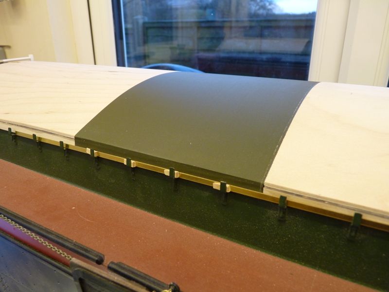
      Tonight I have had a trial fit of the Solartex tarpaulin simulation. I plan to fit this in sections about 5 inches wide to simulate separate sheets that overlap.

      spider 175.jpg

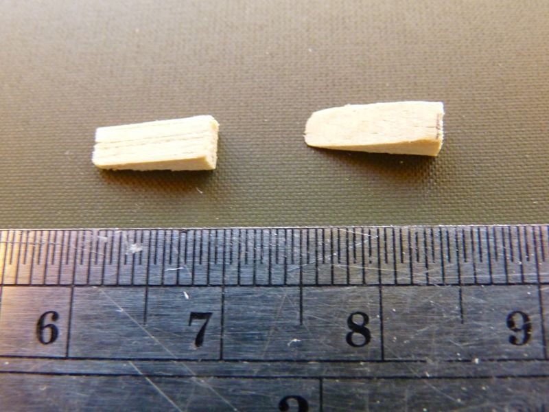
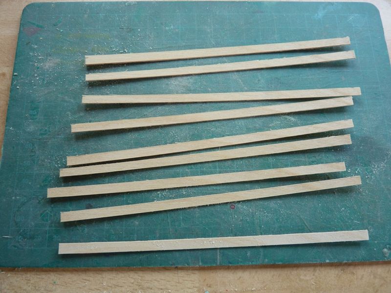
      The hatch bars will be made from 3 mm wide, 0.5 mm thick brass strip. I would have used styrene but I have not got any of the right size but I have the brass. I have also made the first 4 prototype wedges that hold the hatch bars in position. These have been made from some 3 mm x 2 mm timber, not sure what, possibly spruce, tapered on my disc sander to about 12 degrees and 8 mm long which looks about right.

      spider 176.jpg

      At some point I need to make 68 of these wedges, near enough all the same size and shape. They will be dyed with Colron light oak wood dye. The hatch bars and wedges will be stuck to the sides of the hatches so they just rest in the cleats on the coamings and don't actually get wedged in properly otherwise removal and refitting the hatches would be difficult and I don't fancy having to remove 68 wedges every time I take the hatches off.

      I have tried fitting a second piece of Solartex to overlap the first but it is so thin, the seam is almost invisible. I am going to have to fold over the edge of each piece before fitting to make the seams more realistic.

      Gareth

      #75436
      Banjoman
      Participant
        @banjoman

        Gareth,

        This build remains absolutely lovely to look at and very, very interesting to follow!

        For the mass production of wedges, if you have a look about halfway down on p. 11 of my Eilean Mòr thread, you'll see how I went about the same job a while back: http://www.modelboats.co.uk/forums/postings.asp?th=101076&p=11.

        By the way, wen then using those wedges, I found that they stay in place and secure the battens much better if they are put in with the hypotenuse face against the batten rather than the long side of the right angle …

        Mattias

        Edited By Banjoman on 28/01/2018 07:58:08

        #75555
        Gareth Jones
        Participant
          @garethjones79649

          Mattias,

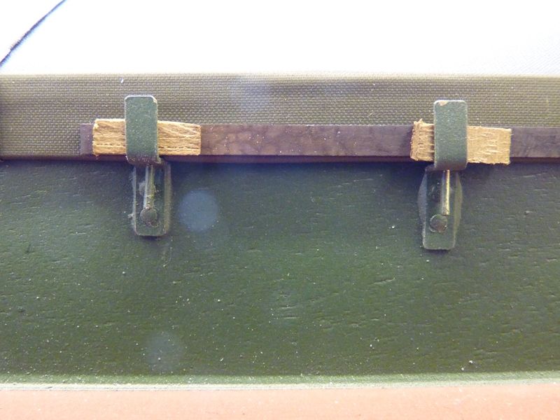
          Thanks for the reminder about your Puffer thread. There are quite a few areas where you had some good ideas I can use on Spider J as they have quite a lot of rigging in common. However I have deviated from your method of making the hatch wedges. I made up an aluminium spacer to use on my disc sander platform so I could hold the relatively narrow wooden strip against the disc at a fixed shallow angle. I have just sanded the tapered section and then cut them off to length afterwards. It means I used roughly twice as much timber as you, per wedge, but they are only small and its only an off-cut anyway. Here are a couple in place after they have been dyed.

          spider 180.jpg

          The brass hatch bars have been blackened. I am not sure yet whether I am going to paint them. The final look I want for the sloop is a well used but not necessarily abused appearance.

          Gareth

          #75556
          Gareth Jones
          Participant
            @garethjones79649

            Ray,

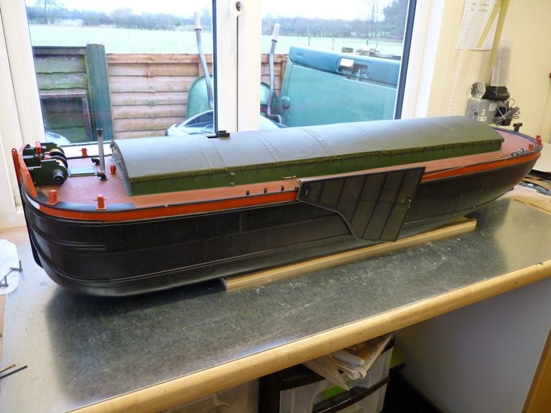
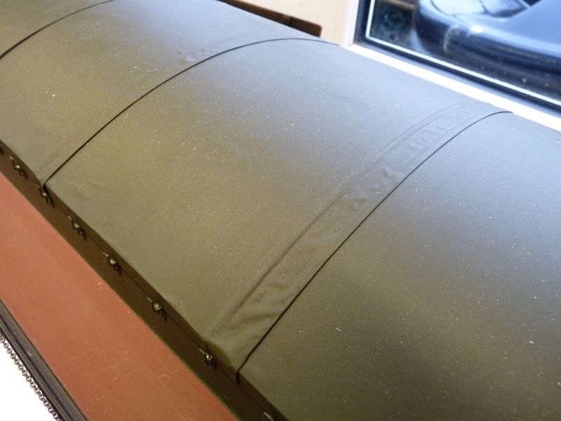
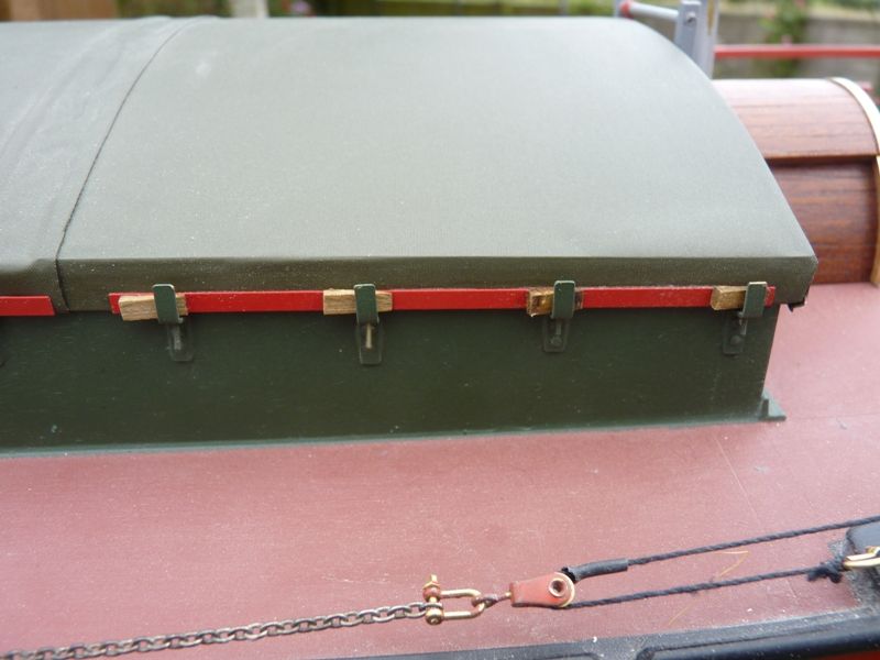
            Solartex does give quite a good impression of a tarpaulin. All three hatches have now been covered. There is a very small overlap on either end of the centre hatch which hides the joints in the hatches very well. The material I have used is satin finish dark green.

            spider 177.jpg

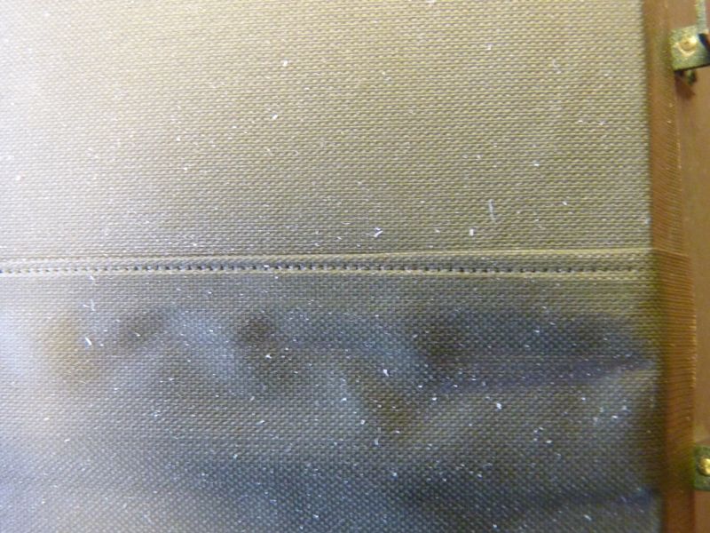
            I have done the covering in a number of sections, roughly representing sheets about 8 feet wide. Initially I folded the edge over to make a seam but, even folding 3 or 4 times it still looked too thin and lost in the overall look. Eventually I incorporated a strip of styrene, 2 mm wide and 0.3 mm thick which looks reasonably convincing, although perhaps now slightly too thick. The styrene strip was ironed on, near to the edge of the Solartex using the adhesive backing and the Solartex then folded over and ironed on the underside of the strip as well.

            spider 178.jpg

            The panels were overlapped and ironed down in turn to fix them on the ply hatch cover. There is the odd small wrinkle and bubble but the tarpaulins were never ironed down completely flat in real life. I ran a small clock gearwheel along each seam to simulate the stitches. Its not easy to see unless you look closely but at least I know its there.

            spider 179.jpg

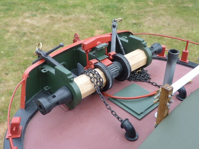
            I have been trying to finish off various details that got abandoned in a partially complete state when I moved on to something new. The brass anchor chain has been blackened, as have all the brass fittings for the lee-boards and the front head ledge winch. There are still quite a few details that need painting, including the deck horses and the front winch. I have also started to shape a piece of timber to make the tiller arm. I will post some pictures when I find a way of forming it into shape, which is probably going to involve some steaming.

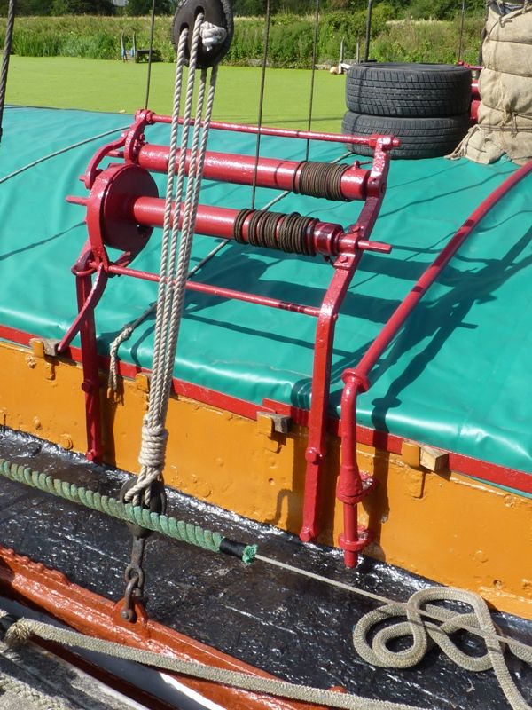
            I think the next major sub assembly project will be the two coaming mounted winches which hoist the sails and gaff boom. This will be made in styrene and brass as it needs to be robust since it will end up taking some of the sailing/rigging loads. Here is a picture of the real thing. There are two, one on either side just aft of the mast. Having a real example to copy is a great benefit when it comes to trying to get all the details right. There are a few hatch bar wedges to compare as well.

            spider 181.jpg

            Gareth

            #76135
            Gareth Jones
            Participant
              @garethjones79649

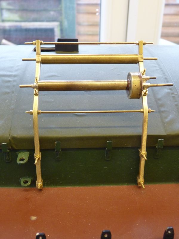
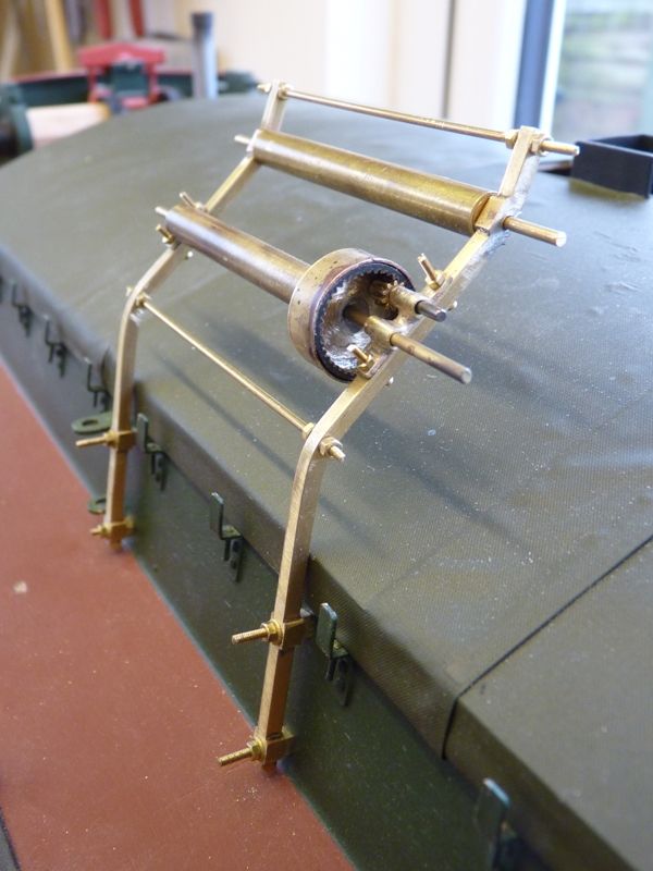
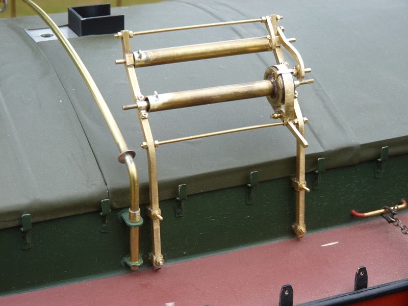
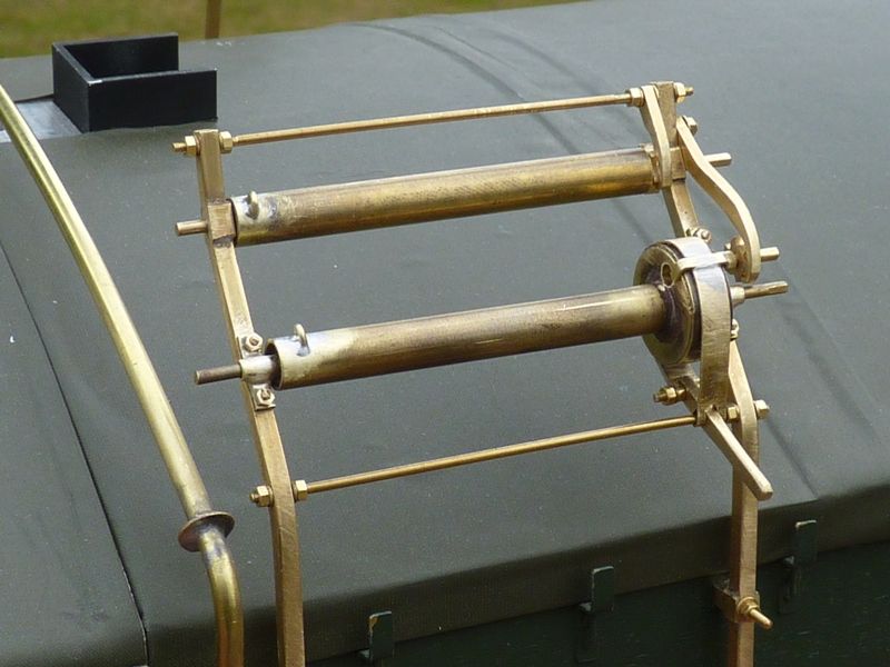
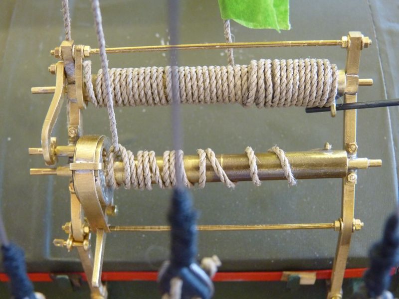
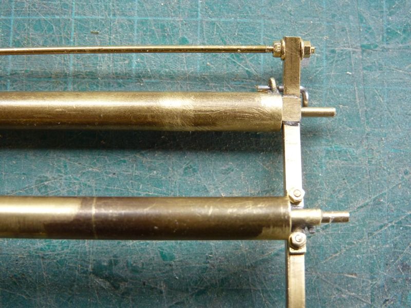
              The first of the coaming mounted halyard winches has progressed quite well, if rather slowly. I usually make a prototype example first and then the final versions but in this case the prototype looks good enough to be the final version of the port winch. It is made from brass square section uprights (2.5 mm), rod and tube, fastened together and to the coaming with a mixture of 12 BA and 14 BA nuts and screws.

              spider 182.jpg

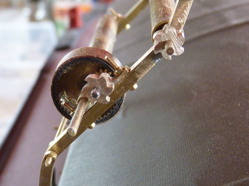
              The top roller operates the foresail halyard and the lower one, which has a low and high gear arrangement operates the gaff peak halyard. The internal gear on the larger diameter section has been made from a length of toothed belt recycled from an old printer. The small pinion is taken from a small electric motor reduction gearbox. The screws all need cropping to length, although I am pondering whether for realistic accuracy, it is worth replacing them with hexagon headed bolts, rather than continuing to use cheese headed screws that I happen to have in stock.

              spider 183.jpg

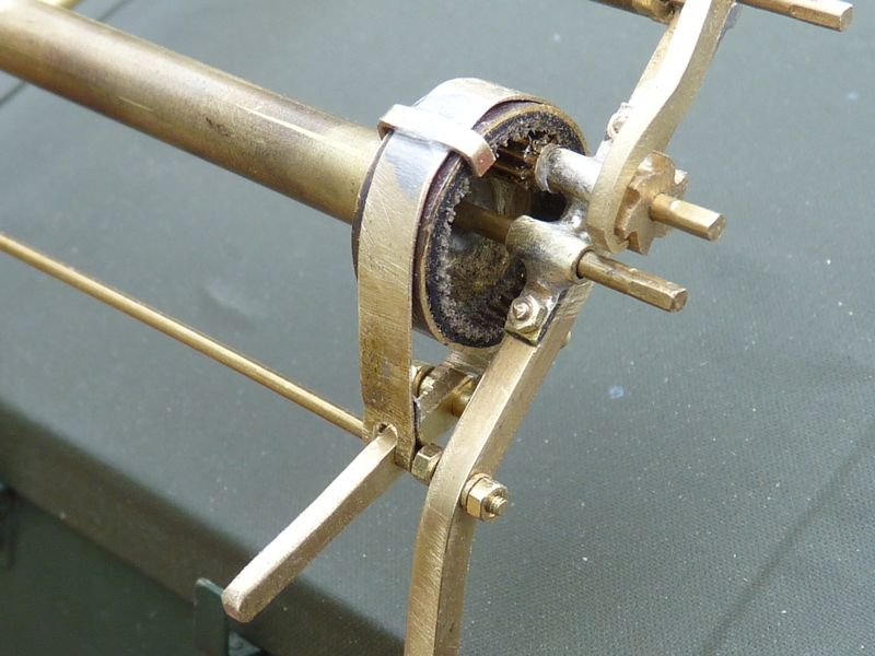
              The next parts to make are the brake, which clamps around the large diameter piece of tube and the pawl and ratchet mechanism that goes on the end of each roller. Making a 6 mm diameter ratchet from a small brass disc could be a challenge. I don't have a lathe so my usual starting point for something like the ratchet will be a small brass pulley, filed down to the right diameter in my pillar drill..

              When this side is complete I have to make another identical, but handed winch for the other side. That one operates the gaff throat halyard and the topping lift (which holds up the aft end of the mainsail boom).

              Gareth

              #76158
              Banjoman
              Participant
                @banjoman

                Gareth,

                That winch looks absolutely fantastic!

                My favourite dealer by far for miniature fastenings of any kind is Dieter Knupfer (**LINK**). As far as I can see, his website is in German only, but if one is willing to deal with that, I find both assortment, quality and prices to be very, very good indeed — and a fair bit of the stuff is his of his own make. I don't think he furnishes anything in BA sizes, though, so if that is a requirement, his site will of course be less interesting …

                Mattias

                Edited By Banjoman on 06/03/2018 13:26:56

                #76163
                Gareth Jones
                Participant
                  @garethjones79649

                  Mattias,

                  I get most of my miniature fasteners from two sources,

                  Eileens Emporium who stock a good range of fasteners and a very wide range of brass sections. Their website is here **LINK**

                  BA bolts has an even wider range of fasteners, see their website here **LINK**

                  There is no particular reason for using BA fasteners rather than metric, I have just accumulated a few 10, 12 and 14 BA screws, nuts and washers and keep using them as appropriate. Maybe one day I will standardise and go metric.

                  On a slightly different topic, one material we use frequently for our vintage yacht restoration projects is T section brass, ideally about 8 mm x 8 mm and 1 mm thick. It's needed for jib racks, shroud plates and deck eyes. This is really difficult to come by in the UK, there are plenty of examples much smaller and much bigger in section but nothing the right size. I was forced down the route of cutting down H section for Serica and China Boy but that is a bit of a waste. Old brass curtain track is useful as a starting point but also almost impossible to find now. As a result I tried a source in Germany last week. **LINK** They do 1 metre lengths of 8 x 8 x 1mm and lots of other sizes. The postage is a bit expensive but I ordered it on Tuesday afternoon and received it on Friday morning, despite it being the worst weather in Europe for years – excellent service.

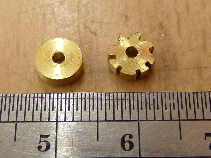
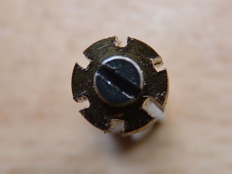
                  On Spider J I have started trying to make the first prototype 6 mm diam ratchet. The basis is an 8 mm brass pulley, filed down to 6 mm in my pillar drill. I then tried to cut 8 equally spaced radial slots with a small hacksaw and then started filing the shape of the teeth. The method has some promise, but the difficult part is getting the radial saw cuts equally spaced and equally deep.

                  spider 184.jpg

                  A bit more practice needed I think, or some sort of miniature jig. The hole in the middle is 1/16 inch diameter.

                  Gareth

                  #76220
                  Gareth Jones
                  Participant
                    @garethjones79649

                    I have made a bit of progress on the dreaded ratchet wheels and reached the point where I have a workable, if not 100% accurate representation.

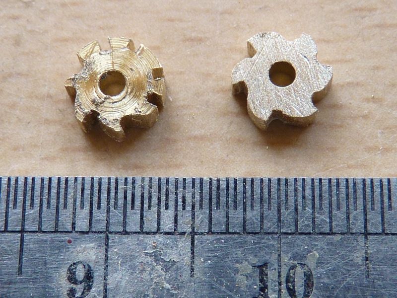
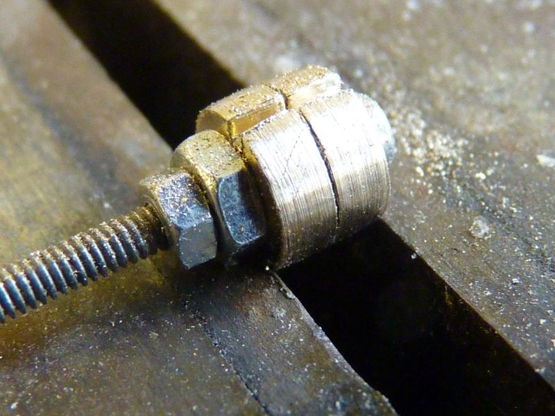
                    I marked out the next attempt by holding the pulley blank in a three jawed chuck and marked it into 6 equally sized sectors using the jaws of the chuck as a guide. I then fixed a screw through the central hole and small hexagon nut with the middle of the flats in line with where I wanted to make the radial saw cuts. I then sawed down to each flat which gave me reasonably identically sized sectors and reasonably similar depths of saw cut. Here's the second attempt after filing the teeth to shape with the first prototype on the left..

                    spider 185.jpg

                    It then dawned on me that I could skip the first step of using a chuck and just use the nut as a guide to the position and depth of the saw cuts. I decided to attempt the next two pulleys simultaneously as shown in the photos below.

                    spider 186.jpg

                    Here's the part after completing the sawing stage and prior to filing the teeth to the right, or near enough right shape.

                    spider 187.jpg

                    After filing this gave me two reasonably symmetrical ratchet wheels, albeit with only 6 teeth when there should really be about a dozen. I had to file the two wheels individually as it was too difficult to get them evenly shaped together.

                    spider 188.jpg

                    While I am in the groove so to speak, I am going to make another two for the winch on the other side then start making the pawls to match. I also have to work out how I am going to lock the two drums on each winch as it is not going to be practical to use the pawls and ratchets to do it because I cant easily fix both the ratchet and the drum on each shaft. After that its the brake mechanism that goes around the large diameter of the lower drum.

                    Gareth

                    #77551
                    Gareth Jones
                    Participant
                      @garethjones79649

                      Maybe the CADMA show inspired me to restart work on Spider J or maybe I was shamed into it by all the people who came up to me and asked where it was and why wasn't it finished. Either way it has been dusted off again and after a fairly intensive spell this week I have just about finished the 2 side winches.

                      In my last post I said I was going to get on and make the next two ratchet wheels but unfortunately I got distracted by something else at the time and ended up having to go back and look at this thread and find out how I had made the first two. The mounting bolts need to be cropped to length but I am going to leave that until I remove the winches for painting.

                      spider 189.jpg

                      There are one or two bits to just tidy up but overall, apart from one aspect I am quite pleased with the result.

                      spider 190.jpg

                      The brake on the lower drum has come out quite well, and it works just like the real thing.

                      spider 191.jpg

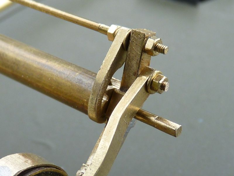
                      Both upper and lower pawls were made by filing brass strip by hand which was a bit fiddly but they look OK

                      spider 192.jpg

                      The one aspect about the winches that niggles me a bit is that the nuts used, which are a mixture of 12 BA and 14 BA look OK on the winch in isolation but are actually about twice scale size. It would probably be impractical to use anything smaller since it would just not be strong enough to take the sailing loads. However when you look at the photo etched 'nuts' that I used to simulate the attachments for the bollards, they look very small in comparison to those used on the winch. I might go up a size on the bollards as a trial.

                      I have also fitted the hatch bars and wedges on the rear section of the main hatch. The bars and wedges are glued to the hatch cover with medium superglue and lift off with the hatch. The wedges are quite convincing, even though they are not actually wedged into the cleats on the coaming.

                      spider 193.jpg

                      I have also done a trial fit of the anchors, which look about the right size. After considering making a pair of anchors, I took the easy option and bought them.

                      spider 194.jpg

                      The next job on the go is the tiller. After several attempts at bending pieces of softwood (which failed because they cracked, even after steaming) or cutting a piece from strip (which looks wrong because of the way the grain runs), I am now attempting to use a 'crook' cut from a small apple tree in our front garden. Photos will follow if it is a success.

                      Gareth

                      #77561
                      Bob Abell 2
                      Participant
                        @bobabell2

                        Hi Gareth

                        I like the lovely neat realistic detailing work on your barge

                        Museum quality again

                        Can I mention one little point?……

                        The ratchet wheels would look nicer if you turned a groove on the faces, to give a hub effect

                        Sorry to nit pick

                        Regards…….Bob

                        #77571
                        Gareth Jones
                        Participant
                          @garethjones79649

                          Hi Bob,

                          You are welcome to pick my nits anytime you like. In response to your suggestion, I don't have a metal working lathe, so I am not able to turn a hub on the face of the ratchet wheels. Its well beyond the capability of our simple wood turning late or my 'lathe substitute' pillar drill. A metal working lathe is on our shopping list, along with a planer/thicknesser. Unfortunately a new sewing machine for Elizabeth is currently at the top of the list.

                          Regards

                          Gareth

                          #77591
                          Gareth Jones
                          Participant
                            @garethjones79649

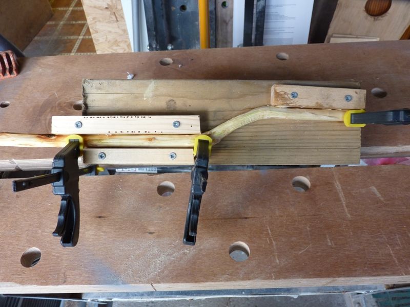
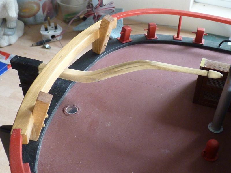
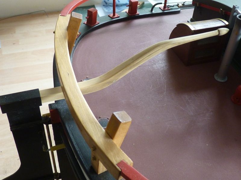
                            The apple twig tiller has turned out really well. I started with a twig about 15 mm in diameter and roughly the right shape for the tiller, i.e. a very elongated 'z' shape. I shaved the bark off and then planed it roughly square section so it would lie flat. At this stage is was overall much longer than the required length. I steamed it in a kettle and then fixed it in a roughly made jig overnight to get it closer to the required shape.

                            spider 195.jpg

                            Then by a slow process of sawing, planing, whittling and sanding I gradually reduced it to the right length and the correct cross section – 8 mm square at the rudder end and 4 mm diameter at the forward end just before the final tapered 'knob'

                            spider 196.jpg

                            spider 197.jpg

                            The slight drawback to having the tiller is that the sweep of the arm makes it impractical to fix my little 1:16 crewman to stand in an appropriate position. I guess he will have to be moved to a more suitable location when the boat is sailed.

                            Gareth

                            #77594
                            Tim Rowe
                            Participant
                              @timrowe83142

                              Gareth
                              Really nice work on that tiller (and the rest of course!!)
                              You could always attach the crewman to the tiller then he will always be in the right place.
                              Tim

                              #77852
                              Gareth Jones
                              Participant
                                @garethjones79649

                                Tim,

                                Thats a good idea and I will give it some consideration. I think the problem might be that my 'crewman' is a solid resin figure and might be a bit heavy to swing from side to side with the tiller.

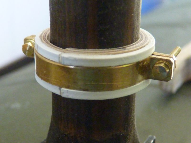
                                I have made a bit more progress with the model over the last week or so. I have made the collar that fits round the mast under the main boom. Just got the bolts to crop to length and then paint it black.

                                spider 198.jpg

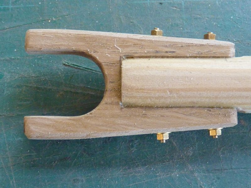
                                I have also made the throat fitting for the main boom as shown below and also the fitting for the other end that provides the attachment for the topping lift and sheet.

                                spider 199.jpg

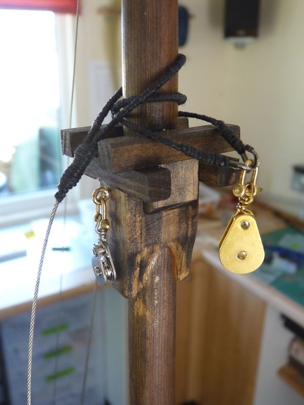
                                I have made a start on seizing all the standing rigging end fittings where there would normally be splices in the wire but in the model's case there are crimps. I have also added all the fixed pulleys for the running rigging on the mast.

                                spider 200.jpg

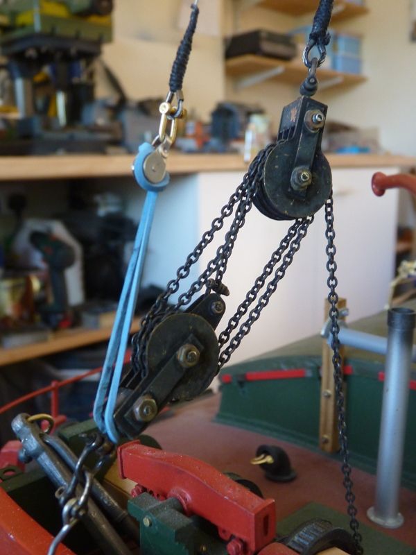
                                I have made the forestay which has to be attached via a pair of pulleys to the bottom part of the stayfall block and tackle. At the moment the bottom pulley and tensioning ropes are replaced with a rubber band.

                                spider 201.jpg

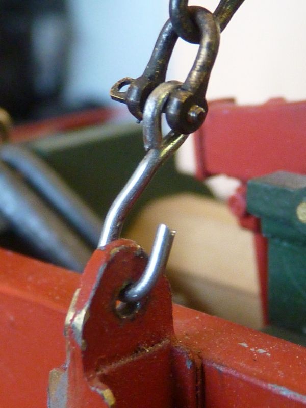
                                After messing around a little in rigging and de-rigging I decided to sacrifice scale accuracy and I have replaced the shackle that attached the stayfall block to the stem extension with a simple steel hook. This makes de-rigging much easier and there is no risk of losing the shackle or its pin in the process.

                                spider 202.jpg

                                During our recent trip to the Isle of Man I discovered that the easiest way to transport the model is to allow the mast to fold backwards by about 40 degrees which gives enough headroom to get it in the back of the car. Previously I had folded the mast fully backwards but that results in the shrouds getting tangled and the chain on the stayfall block also getting in a twist.

                                The current work is continuing to seize the ends of the shrouds and making the gaff boom and its fittings. I have now roughly drawn out a sail plan so I will be passing the sail making task to my wife in the near future.

                                Gareth


                                Edited By Gareth Jones on 01/07/2018 21:36:42

                                #77853
                                Bob Abell 2
                                Participant
                                  @bobabell2

                                  Hi Gareth

                                  Lots of scale fittings and tackle to ponder over!

                                  Nice interesting work to delight the eye

                                  Have you got access to the full size ship?

                                  Will we see you again at Haydock, this year?

                                  All the best to you and your sailmaker

                                  Bob

                                  #77854
                                  Banjoman
                                  Participant
                                    @banjoman

                                    Gareth,

                                    That looks truly great!

                                    Are those stayfall chain blocks made from scratch? They really look the business — and from what one can see do the business, too, don't they? I mean, the stayfall tackle works the same as the full size one, doesn't it?

                                    Mattias

                                    #77858
                                    Eddie Lancaster
                                    Participant
                                      @eddielancaster

                                      Another genius at worksmiley you are certainly giving me food for thought building my TSB.
                                      Keep the good work coming!

                                      Regards.

                                      Eddie

                                      #77883
                                      Gareth Jones
                                      Participant
                                        @garethjones79649

                                        In answer to your assorted questions, I have access to three Humber sloops, moored in the marina in Hull, Spider T, whose original build drawings have been used for Spider J (but is now considerably altered from its original build standard), Amy Howson, and Phyllis. Amy Howson and Spider T are both the same size, Phyllis is slightly bigger. I have used a combination of all three in making the fittings and building the model. All three sloops also have their own websites.

                                        We probably will be going to Haydock Park but only as visitors, not exhibitors. If we go it will be on the Saturday as Sunday is a Vintage Model Yacht Group sailing day at Cleethorpes. We will be exhibiting at Blackpool, but probably only vintage model yachts. I don't think we will have room in the car for Spider J.

                                        The stayfall blocks were built from scratch and do work as the original. I have not yet decided on a locking mechanism, which is typically by a shackle through the chain at a suitable location. Mine is just locked with a small brass pin through the chain at present.

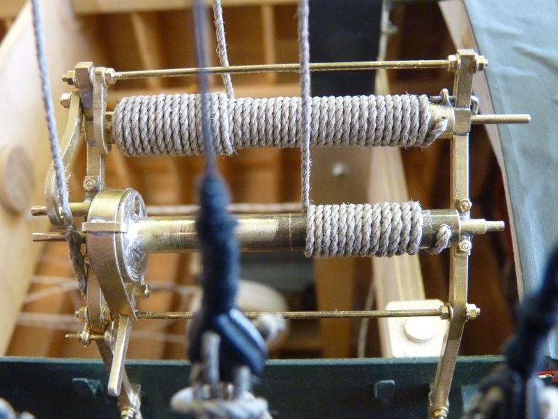
                                        I have started doing an experimental bit of rigging of the lines for the topping lift and gaff throat which go to the winch on the starboard coaming. The problem which I anticipated, and have not yet resolved is securing the lines on the rollers but preferably making them adjustable. I cannot easily lock the rollers and prevent them rotating as the pawl and ratchet mechanism cannot be relied upon and in any case the ratchet wheels are not securely fixed to the rollers.

                                        The picture below shows two methods tried so far.

                                        spider 203.jpg

                                        In the top one, I have locked the roller with a pin (actually a small drill), through an eye in the end of the roller. This looks clumsy, even if I use a smaller pin, but it is easy to wind the cord on the roller by spinning the roller with my fingers. The few coils of line at the left hand end are just held on the drum with double sided tape. The end of the cord should go through an eye in the roller but the ones I made are too small and need to be replaced by bigger ones (but not as big as the one at the RH end of the roller.

                                        In the bottom one the line is looped over itself where it comes on to the drum and then wrapped around the roller by hand. This works quite well and is quite unobtrusive but its a pain to wind the line round the roller and difficult to adjust afterwards.

                                        At the moment I am inclined to use the second method but with a discretely positioned bowsie in each line to provide adjustment – unless I or someone else can come up with a better idea. Maybe I need to have a look at some Thames barge models and see how they do it.

                                        Gareth

                                        #77885
                                        Banjoman
                                        Participant
                                          @banjoman

                                          Gareth,

                                          For my part, I am inclined to think that you would bet better off with the first alternative, i.e. a locking pin.

                                          If you were to make the eye on the end of the roller as unobtrusive as you could get away with, without compromising to much on its strength, and also moved it as far to the right (as shown in the photo) of the roller as possible, and the drilled a hole for the pin through the upright strut, I should both work and look "right".

                                          Although it would of course be a deviation from true scale representation, I don't think that it would look clumsy at all, but quite realistic and "made", if you see what I mean. You might even consider inserting two or three such (smaller) eyes around the circumference of the roller, to give you a choice of locking positions for more precise adjustment …

                                          Mattias

                                          #77890
                                          Banjoman
                                          Participant
                                            @banjoman

                                            Gareth,

                                            A further thought: if you were to drill and tap a hole through the upright strut, you could then use a suitable small brass bolt instead of just a plain pin to engage with the locking eye on the roller. That way, there'd be no risk of it falling out during transport or while sailing. In consequence it could be kept fairly short and thus be more unobtrusive, while I'm sure that a fitting socket wrench hex key just held between the fingers would give more than enough purchase to engage and disengage the bolt with ease.

                                            This would of course add a detail to the winch that isn't there in full size, but I think it would look like something that could very well have been included on a real winch as a security backstop to complement the pawl-and-ratchet arrangement, rather than as a clumsy makeshift solution.

                                            Mattias

                                            #77899
                                            Gareth Jones
                                            Participant
                                              @garethjones79649

                                              Excellent ideas Mattias, I have embodied the first suggestion and I might do the second as well but I think it looks fine as it is now.

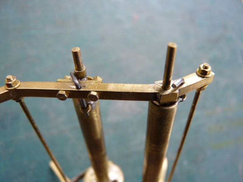
                                              I have drilled a 1.0 mm hole in the side frames, adjacent to each roller. To locate the hole accurately I pushed the 1/16 inch brass roller pivot rod through the side frame and fitted the roller to the outside of the frame. I then pushed a piece of 1.0 mm piano wire through the small eye in the end of the roller and used that to mark the side frame. For the roller in which I had fitted a bigger eye, I have reverted to my original small one.  I only have one eye in each roller as there is no need for very precise adjustment of the rigging lines.

                                              The locking pin is a short piece of 1.0 mm piano wire bent to an L shape. The top one is visible, but not very obtrusive, the bottom one is hidden behind the side frame.

                                              spider 204.jpg

                                              spider 205.jpg

                                              I could tap the side frames for a 12 BA bolt but I think the piano wire solution is stronger and simpler, and I don't have a 12 BA tap at present. The locking pins are a good fit and with the tension in the rigging lines, I don't think they will fall out.

                                              I also made another small mod and drilled a 1.3 mm hole near the end of each roller. The free end of the line is pushed into this hole, after application of a small amount of superglue to stiffen it. A short piece of double sided tape on the roller (just visible on the lower roller) helps secure the end of the line.

                                              spider 206.jpg

                                              The next step is to do the same mods on the other side and then complete the rigging lines for the gaff boom and foresail halyard. I can then start to make a pattern for the sails.

                                              Gareth


                                              Edited By Gareth Jones on 04/07/2018 16:09:28

                                              #77911
                                              Banjoman
                                              Participant
                                                @banjoman

                                                Gareth,

                                                That looks seriously good, and in my view completely realistic, in the sense that one could perfectly well imagine a real winch having a similar security locking arrangement. A true expert on these winches (I'm sure there are a few out there) might say "oh, I've never seen that arrangement before — where did you come across it?", but I would be well surprised if even such a person dismissed the construction out of hand. And of course you are quite right that the tension from the rigging lines should be enough to keep the pins in place through simple friction between pin and eye.

                                                Also, with a pin diameter of 1 mm, I likewise think you are absolutely right to prefer piano wire to a brass bolt — the latter kind of fixing at such a small size as 12 BA might well bend slightly under the pressure of the weight of the spars and sails in combination with the pressure of the wind on the sails …

                                                What sort of surface treatment do you have in mind for the winches? Chemical blackening? Or paint? If the former, I thought I should perhaps mention that I have had it happen to me that soft solder started to dissolve when left immersed for too long (half an hour I think it was, or even a bit more) in the blackening agent. But I suppose you have used hard solder, anyway, given the loads that the winch must be able to stand up to?!

                                                Mattias

                                                #77968
                                                Gareth Jones
                                                Participant
                                                  @garethjones79649

                                                  Mattias,

                                                  There is some silver soldering in the winches but there is also a bit of soft soldering as well. However the winches will be painted rather than blackened so there should be no problems.

                                                  The latest step has been making the mast hoops that attach the mainsail luff to the mast. They have been made pretty well the same way that full sized ones are made. I started with lengths of 1 mm ply, about 5 mm wide. Each end is chamfered over a length of about 10 mm, one end on one side, the other on the other side.

                                                  spider 207.jpg

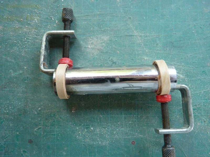
                                                  Each length is boiled in a pan part full of water for a few minutes and then wrapped around a piece of pipe, slightly smaller than the required finished finished diameter and then clamped in place.

                                                  spider 208.jpg

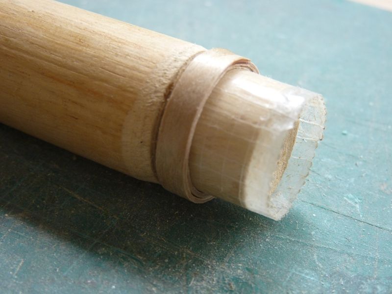
                                                  They are left to cool and dry and then wrapped around a mandrel which will give the required finished diameter. in this case 25 mm outside diam with two complete turns of the strip. I had to make a few samples and trial and error led to the right starting length of the strips and diameter of the mandrel. The mandrel has a length of clear tape around it to prevent the hoop sticking to it.

                                                  spider 209.jpg

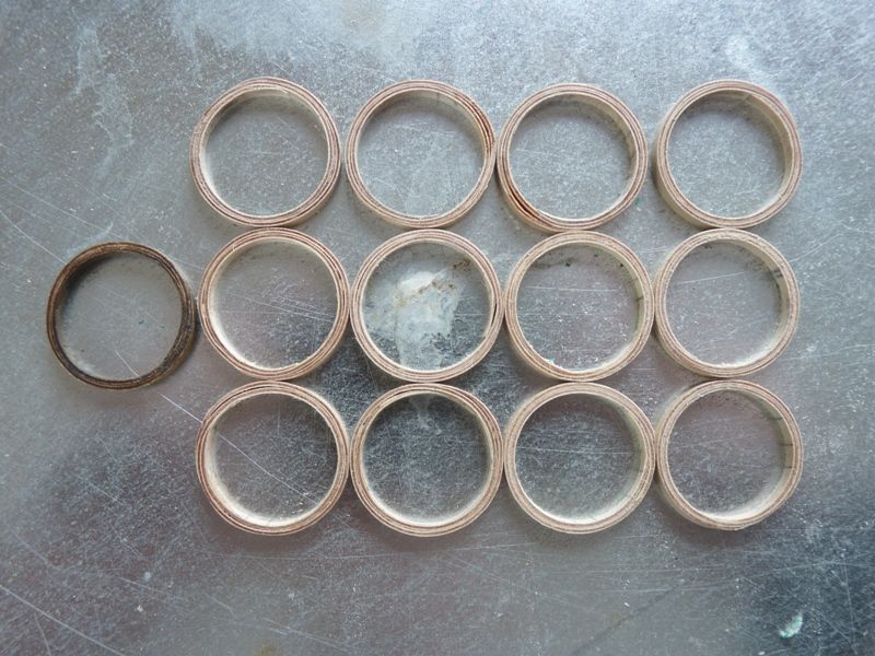
                                                  Thin super glue is dribbled into the edge of the hoop where the two scarphed ends overlap. When it has dried, the hoop is pushed off the mandrel and glue dribbled all around its circumference on each edge so it becomes a solid hoop. You then have to try and prize it off your fingers with minimal loss of skin where it's stuck to your hand.

                                                  When dry, the edges of each hoop are sanded on the disc sander to a uniform thickness of 4 mm, being careful to avoid sanding the ends of your fingers or thumb on the disc. Next the inner and outer faces were lightly sanded with a piece of 180 grade abrasive paper. When they were all made they were soaked in dark oak wood dye and allowed to dry.

                                                  spider 210.jpg

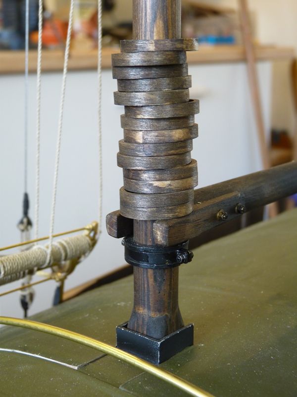
                                                  They have to be fitted over the section at the foot of the mast which is about 17 mm square. The chosen size gave a tight fit but by chamfering the corners of the mast slightly they could all be pushed on and up to the main round section of the mast. The collar that supports the main boom was also fitted at this stage.

                                                  spider 211.jpg

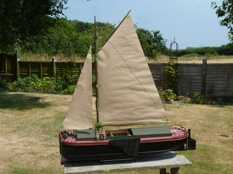
                                                  The next job has been to make an initial pattern for the sails from some brown paper. I am reasonably happy with that now so the brown paper pattern with its required corrections will be transferred onto some of my wife's 'proper' dressmaking pattern paper before marking and cutting out the sails.

                                                  spider 212.jpg

                                                  I have some sailcloth in a suitable tan colour as used on Humber sloops. For some reason Humber sloop sails were tan coloured but keels were white or cream (and square rigged).  I bought the last piece of tan coloured material that Keith Jewell at Modelling Timbers had in stock about 3 years ago, especially for this project, but I don't think I have enough spare for any major mistakes. However Elizabeth plans to make a prototype set from some spare scrap material first so hopefully there won't be any errors in the final set. We are going to follow Banjoman's process as used on his Moonbeam for hemming and false tabling the edges and sewing on the bolt ropes.

                                                  After living with a working name of Spider J for the last three years or so we have now decided on the final name for the sloop (and also a name for the keel when it is built). The model is based on the hull drawings of Spider T but it is really a generic Sheffield sized sloop so I did not want it to be too closely allied to that particular vessel. I am going to keep you guessing what the name will be for the time being. However if you know the name of some of Elizabeth's yachts, it will give you a clue.

                                                  Gareth

                                                  Edited By Gareth Jones on 07/07/2018 17:13:50

                                                  Edited By Gareth Jones on 07/07/2018 17:15:24

                                                  #79921
                                                  Gareth Jones
                                                  Participant
                                                    @garethjones79649

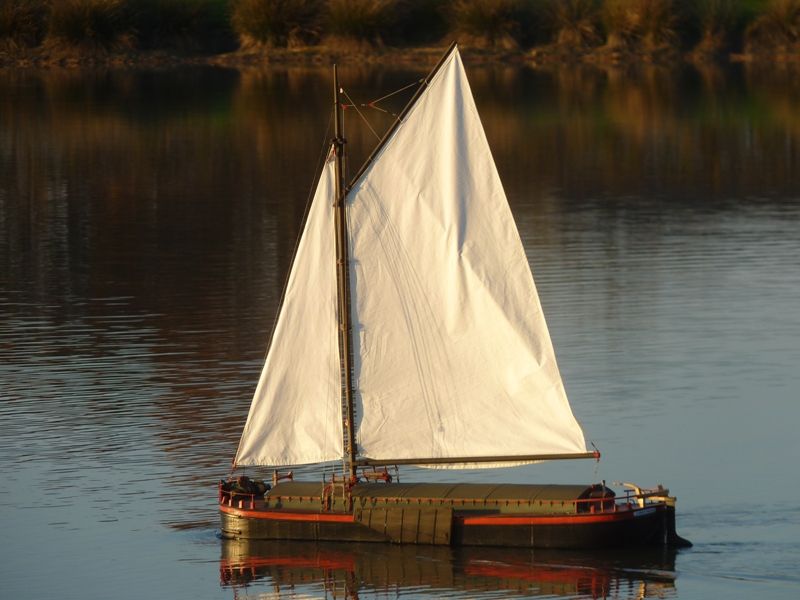
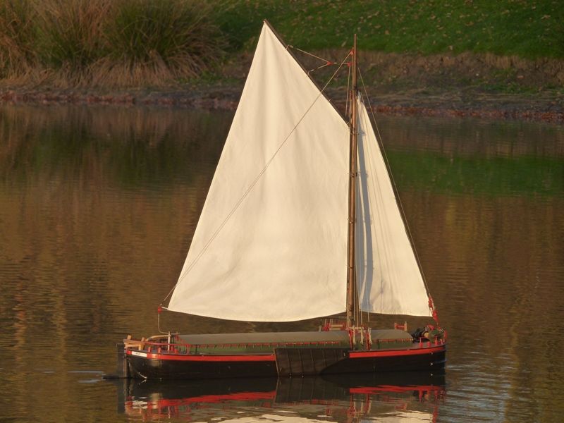
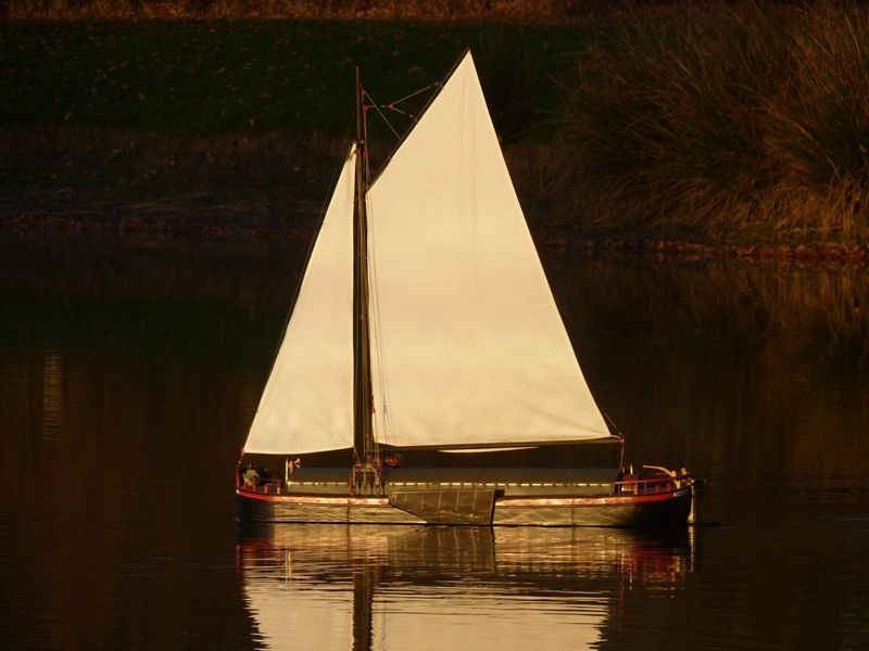
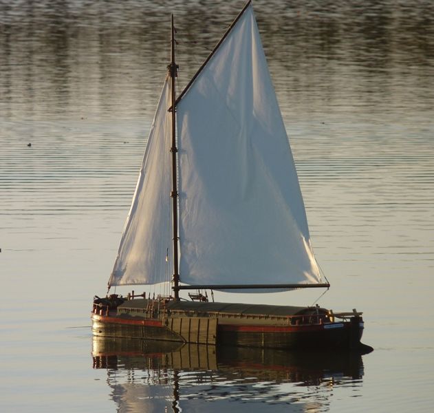
                                                    Spider J has progressed slowly over the last few months and this afternoon we took it for it's first proper 'sail' with a trial set of cotton sails. These have been made by Elizabeth to check the fit and allow us to adjust the template before cutting the final set out of the proper brick red material. There was very little wind but since I am not sure of the ballast yet maybe that's no bad thing. Tomorrow we will check again when there is forecast to be a breeze of around 10 mph. Today's outing was quite successful and allowed us to check the ballast was in roughly the right place and the sequence of fitting the ballast and centre hatch with the boat in the water was quite practicable.

                                                    spider 213.jpg

                                                    spider 214.jpg

                                                    spider 215.jpg

                                                    spider 216.jpg

                                                    Gareth

                                                    #79939
                                                    Ray Wood 3
                                                    Participant
                                                      @raywood3

                                                      Hi Gareth,

                                                      Well done you are getting close to the end of your epic build of Spider J and not cheating by putting a Marblehead keel on for sailing, what are you using for ballast?

                                                      Regards Ray

                                                    Viewing 25 posts - 151 through 175 (of 201 total)
                                                    • Please log in to reply to this topic. Registering is free and easy using the links on the menu at the top of this page.

                                                    Code of conduct | Forum Help/FAQs

                                                    Latest Replies

                                                    Home Forums Scratch build Topics

                                                    Viewing 25 topics - 1 through 25 (of 25 total)
                                                    Viewing 25 topics - 1 through 25 (of 25 total)

                                                    View full reply list.