
Barrie Griffins Vosper MTB 379

Barrie Griffins Vosper MTB 379

Home Forums Beginners Barrie Griffins Vosper MTB 379

Viewing 25 posts - 26 through 50 (of 55 total)
  • Author
    Posts
  • #127348
    John W E
    Participant
      @johnwe

      DSCN1903DSCN1899DSCN1901DSCN1905hi Ray

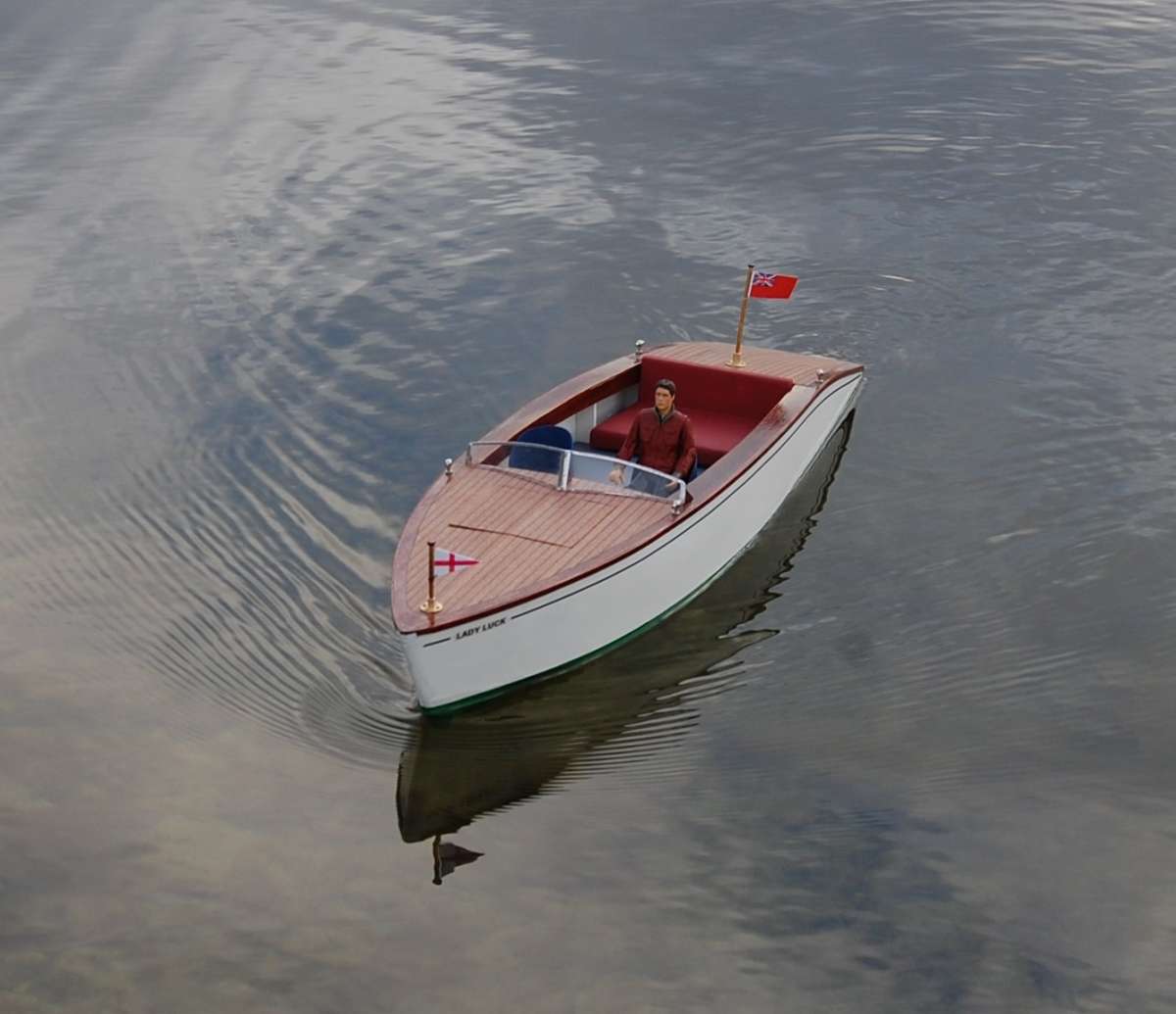
      There is a plan in the model boats magazine for a Slipper Launch that would look rather nice mahogany planked.  Could be on my next ‘to-do’ list and that one would not be painted grey,.

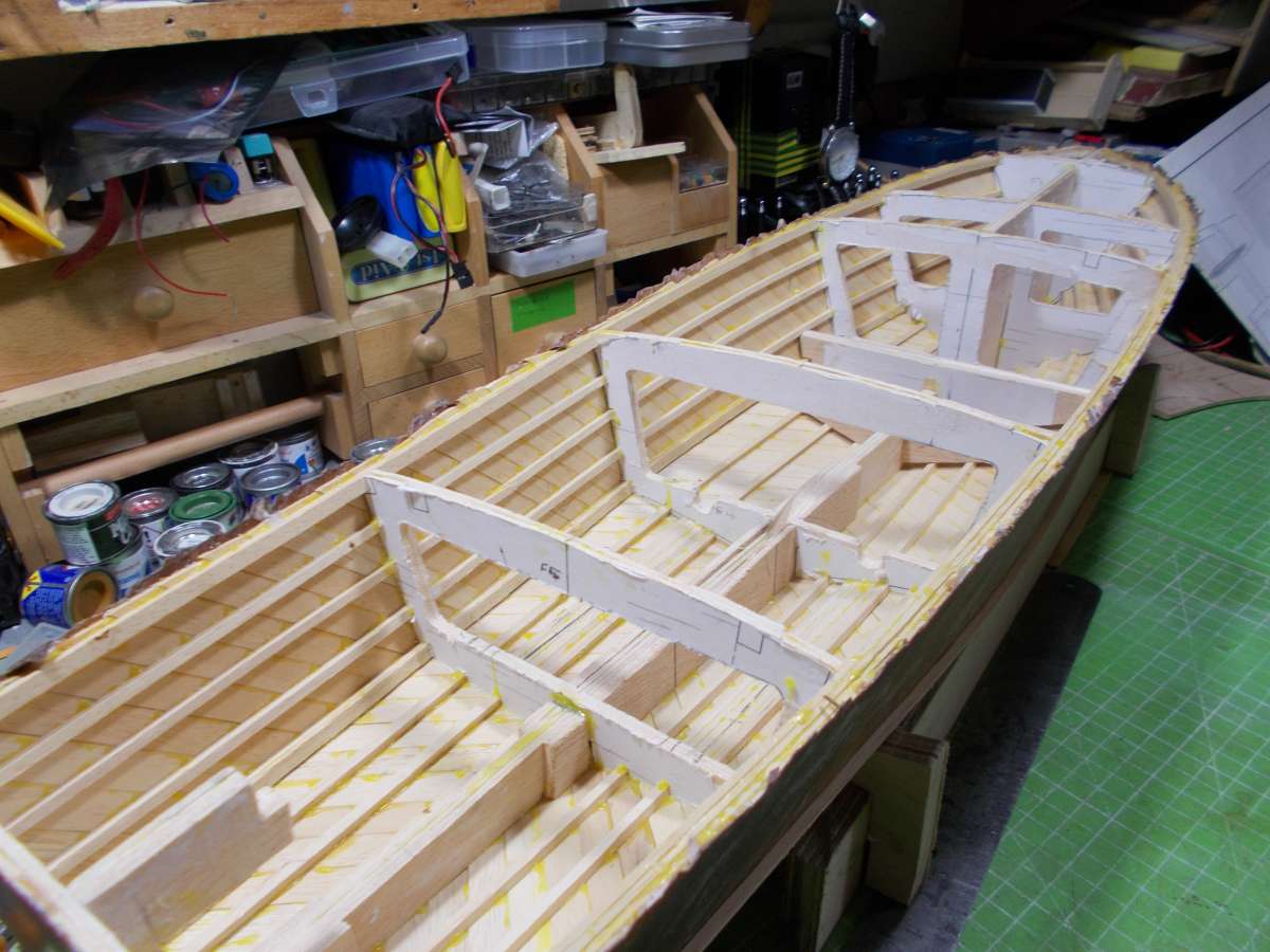
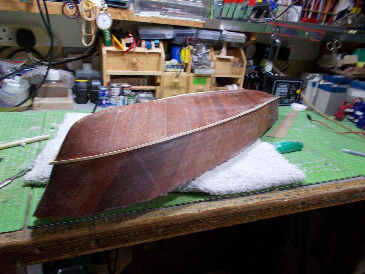
      Carrying on with the building of the grey one; I have finished rubbing down and removed it from the building board.  I tried something new with attaching the frames to the building board on this model as I used hot glue instead of square wooden blocks to attach the frames to the board.  When I finished the planking of the hull and removed the model from the building board I just used a flat bladed screw driver to remove the model from the board.

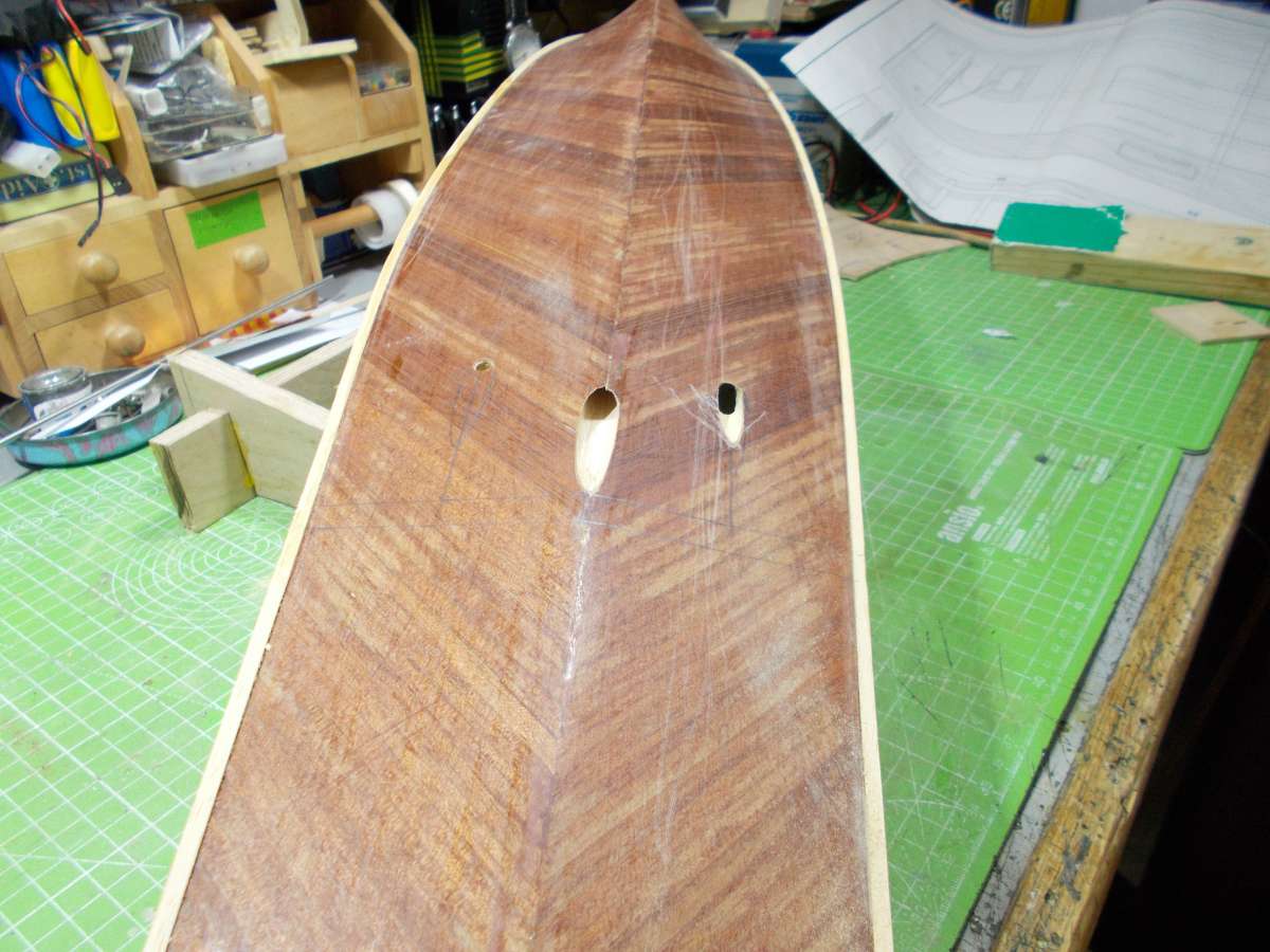
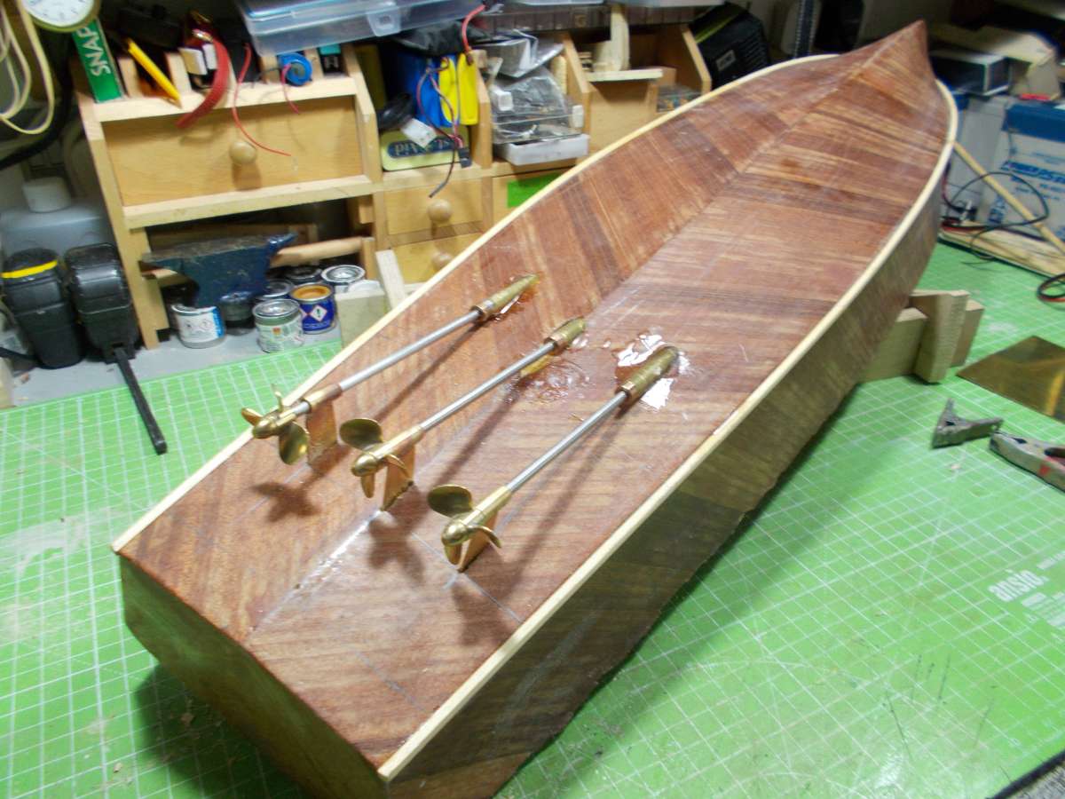
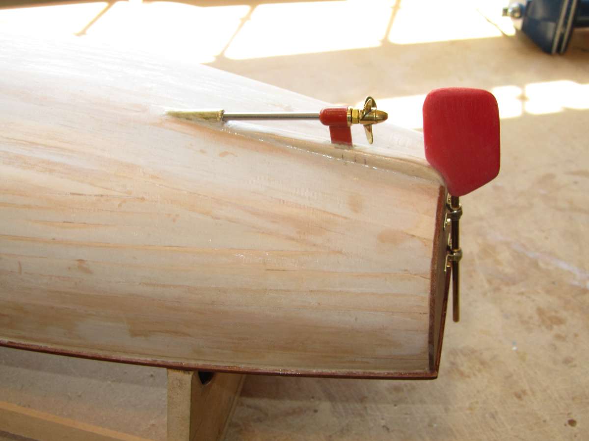
      Next, I fitted the chine spray rails which I made from 1/8 square obechi.  This was super glued in place.   Next, I marked off the position of the prop shafts – and – further deviation from the plan – I added the centre prop which is as the originals.

      John

      #127350
      Ray Wood 3
      Participant
        @raywood3

        Hi John,

        Yes Lady Luck my latest design would look great in Mahogany maybe bigger slightly it was a fiddle getting the gear in 🙂

        Regards  RayLLOTW1

        #127360
        Philip Oxley
        Participant
          @inonowt

          Hi John.

          Really good to see your progress on the MTB.

          I’m fitting 2 shafts in mine and have 4mm shaft supports.  Which prop shaft/tubes did you use?  I’d prefer to use plain ended shafts with a collet to take up the reverse thrust.  Presumably I fit a collet to the shaft at the end of the tube for the forward thrust, so it’s not against the supports.  Have I got that right?

          Regards

          Philip

          #127361
          Colin Bishop
          Moderator
            @colinbishop34627

            Yes, put a collet at the end of the tube to take the thrust. The supports are there to align the shaft, not transmit loads.

            Colin

            IMG_7448

            #127362
            Philip Oxley
            Participant
              @inonowt

              <p style=”text-align: left;”>Thank you Colin.</p>

              #127364
              John W E
              Participant
                @johnwe

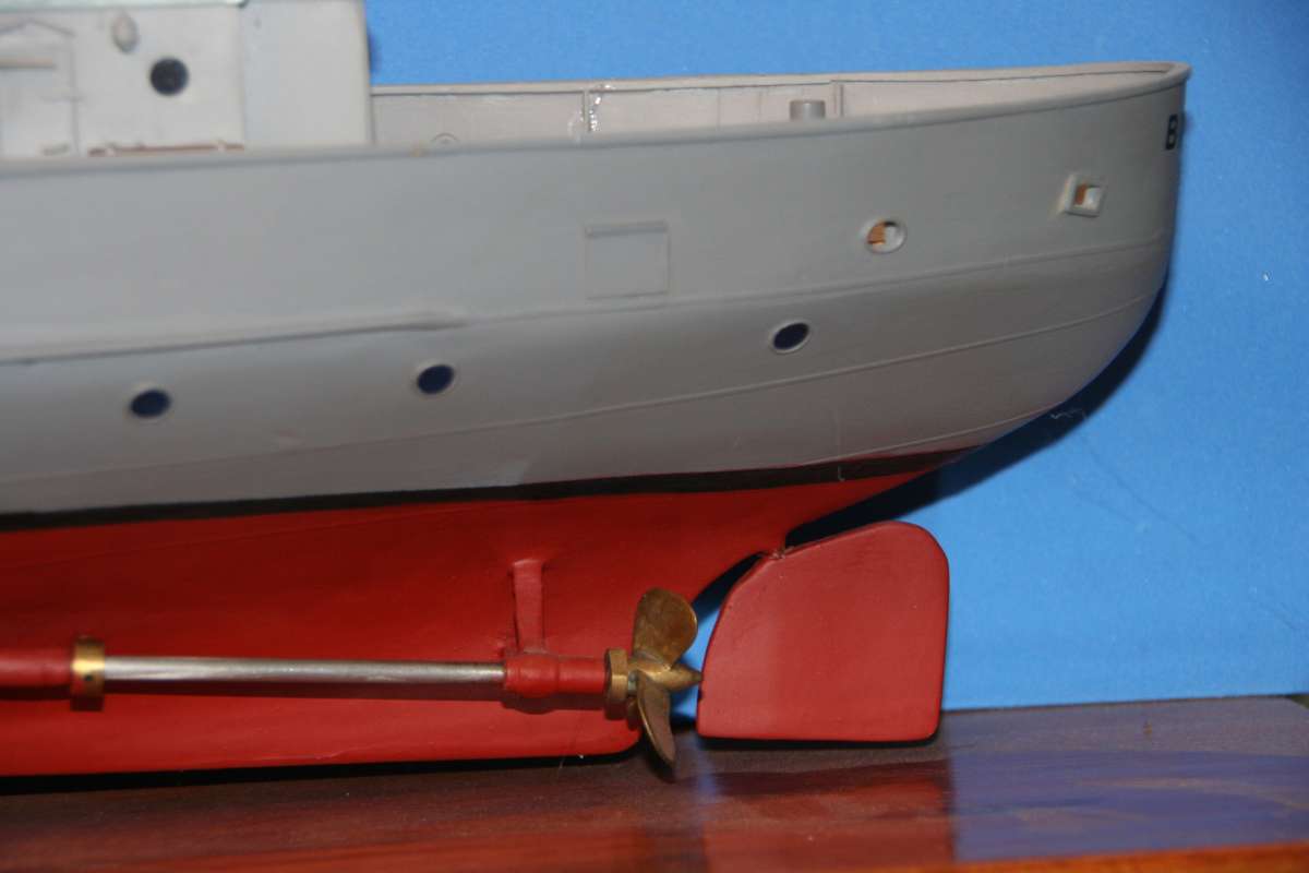
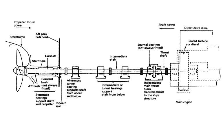
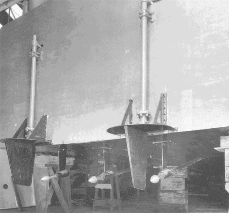
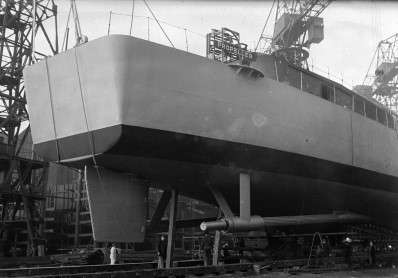
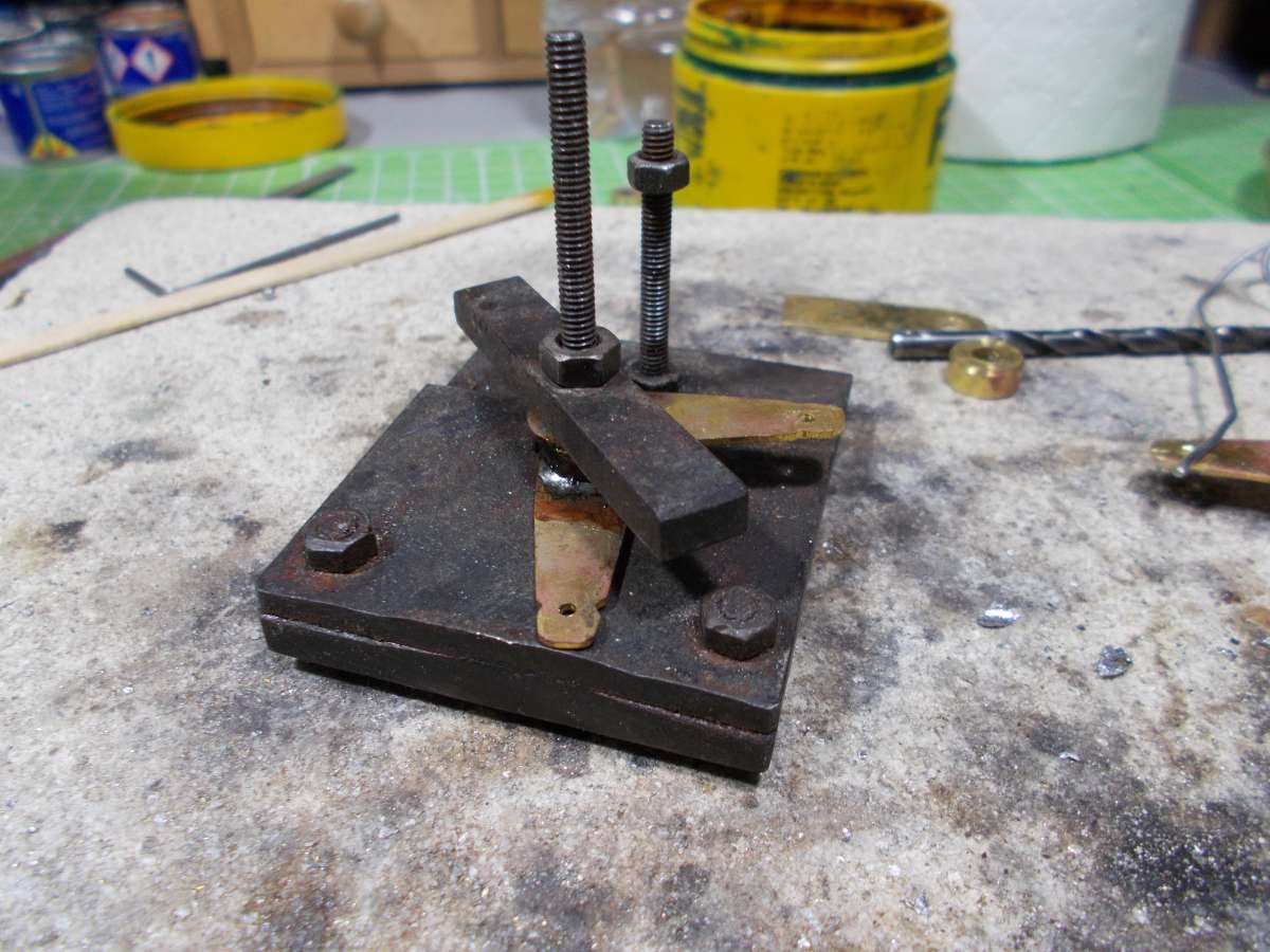
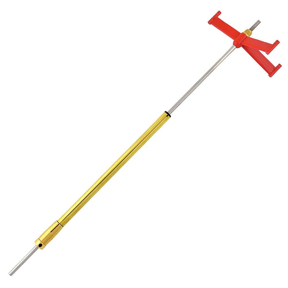
                propeller-shaft-arrangementDSCN1912rudder100713…. as they say, horses for courses .. I very rarely used a thrust ring on the exterior of a prop shaft – I tend to strengthen the ‘A’ frame or, ‘P’ frame and bond it well into the hull, allowing the thrust of the propeller to be taken up by that frame.  Obviously we may have some people saying Wrong and some saying Right.   However, on the life sized ships the thrust is actually taken up inboard just before the power unit on a thrust block bearing and a thrust ring on the prop shaft.  This can be difficult to duplicate in a small model.  Also, we have to take into consideration the really small amounts of thrust that we are using; comparing to let us say a racing model.

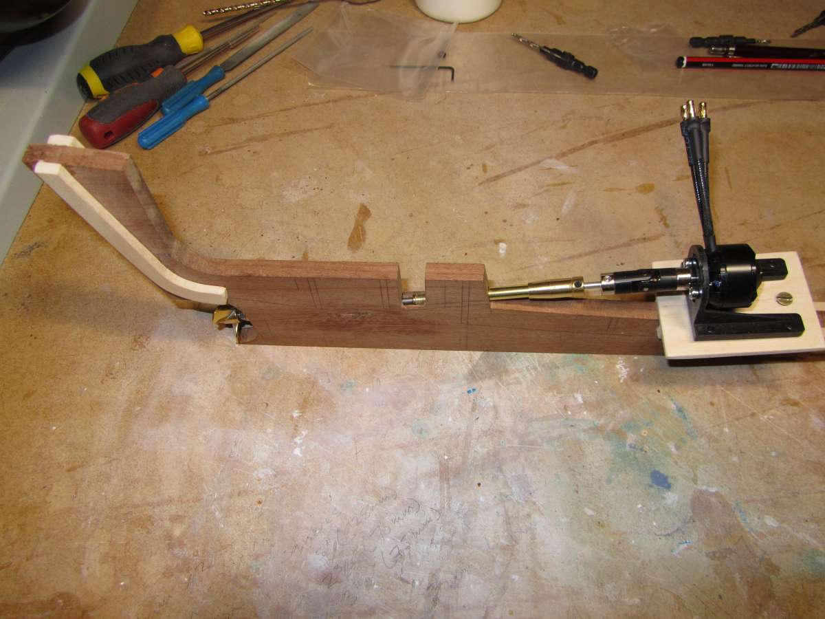
                Where I will use a thrust ring on the prop shaft is inboard of the model, when I have a long exposed section of shaft say from the end of the prop shaft to the motor, as I have in this model. So, I will be using internal thrust rings.

                John

                #127365
                Chris Fellows
                Participant
                  @chrisfellows72943

                  I’m glad that Colin mentioned this as it prompted me to check my Faun and I had forgotten to fit a collar. But before reading John’s post I’d already started pondering whether I actually needed to?

                  Reason being the Faun is small at only 16″ and will be low speed so forces won’t be that great. The P bracket is plastic but quite strong. Also I ended up fitting the prop tube almost into the keel and painted over the end (which I don’t really want to remove and risk water damage) there isn’t much room for a collar.

                  But my over-riding reason (I’ve decided!) is that brushless motors (as I tend to use) are pretty good at resisting thrust and so I’m going to ensure there is clearance between the prop and P bracket and let the motor take up the forces which as I said be low and this model is never going to be used that much anyway.

                  If you think about it, with an aircraft, the prop is connected directly to the motor, and with a big prop and high revs the force is going to be considerable, much more than that in slow to medium speed model boats? Also, with my water-jet the motor is connected directly to the turbine. I think I’ve convinced myself!

                  Don’t know about about brushed motors but I assume they can handle some thrust as well? I can well see the need in the example you posted Colin, as the arms to the struts are slender.

                  Chris

                  Rudder 9

                  #127366
                  Colin Bishop
                  Moderator
                    @colinbishop34627

                    I can well see the need in the example you posted Colin, as the arms to the struts are slender.

                    And the boat is pretty heavy too! Horses for courses as usual.


                    #127367
                    Ray Wood 3
                    Participant
                      @raywood3

                      Hi All,

                      A little case of over thinking here !! if the shaft has lock nuts secured against the prop and the coupling at each end no thrust is transmitted to the motor in the slightest, only my view obviously 🙂

                      Regards  Ray

                      #127369
                      John W E
                      Participant
                        @johnwe

                        couple of things for thought/to ponder over

                        With regard to an aeroplane prop, connected directly to the motor – yes, we are using the motor bearings to absorb the thrust – however, between the motor and the prop there is a solid connection – no weak link.

                        On the majority of model boats, we place a coupling between the prop shaft and the motor to allow for slight mis-alignment.   If we have no means of absorbing the thrust before the coupling, the coupling will absorb all of the thrust and the coupling will become the weakest point because it will not be transferring the thrust of the prop in a straight line.   One way around this is to use a solid coupling.   So, in theory, if we are going to use a prop shaft which incorporates an open piece of prop shaft which is supported by an ‘A’ or ‘P’ frame, we must try to achieve the alignment of the motor, prop shaft and coupling as accurate as possible.  The smallest mis-alignment will see failure eventually of the coupling,  (if we are using a straight line from propeller to motor thrust).

                        One solution is to use a solid coupling, rather than the hugo plastic couplings, you know the ones, the ones with the red insert – I have a drawer with some of these couplings in and one or two of them the splines are out of line and the brass inserts will not line up truly.

                        Ray, I agree with what you are referring to about the lock nuts, but your theory is only applicable on a full length outer tubing – whilst we are discussing here an open section of prop shafts set up.

                        John

                        #127370
                        Chris Fellows
                        Participant
                          @chrisfellows72943

                          Good, informed discussion as usual. John, of course you are right about the coupling and I have used a Huco type coupling in Faun but a better quality one than those red ones and so I’m not overly concerned about the low thrust that will be transferred through it and it is accurately aligned – I need another one so will get some spares though. I did remember to fit the collar at the top of the prop shaft, though given my logic for this model, it isn’t really needed.

                          I’ve used the same prop shaft and coupling for my Fisherman but the bearing from the P bracket will be glued directly into the keel, so no problem there and this is a much bigger, heavier model.

                          As you say Colin, horses for courses and each situation has to evaluated accordingly.

                          Hull Keel 24

                          #127372
                          Colin Bishop
                          Moderator
                            @colinbishop34627

                            Most of my boats are relatively small and my usual practice is to use pulley drive which sidesteps the issue of lining up a coupling and has the added benefit of enabling a geared reduction between high motor RPM and the need for lower propeller revolutions. This greatly reduces current consumption and is a win win. I have never needed watercooling or anything like that.

                            Even my big 47 inch fishery cruiser benefits from this with its two 540 low drain motors 0n 2.5 ratio reduction drawing just 2.5 amps at cruising speed.

                            Likewise my Greek Fishing Boat draws next to nothing using an old Monoperm motor and a 2:1 reduction drive.

                            My current Silver Mist build also has pulley drive with minimal  power consumption using two 280 size motors.

                            The reality is that with model boats, direct drive is inherently inefficient as there is such a great disparity between optimum motor RPM and optimum propeller RPM. Anything that can be done to bring them together really pays off in terms of power consumption and running time.

                            My two Fairey powerboats use direct drive with semi rigid couplings but use the greater efficiency of brushless motors to compensate for the driveline power losses.

                            Colin

                            #127383
                            Richard Simpson
                            Moderator
                              @richardsimpson88330

                              In the August ’24 edition of the magazine in Boiler Room 155 there was an article discussing thrust arrangements.

                              The biggest concern I would have, if there is no means of accommodating thrust, even with low powers, is that the thrust then ends up being taken up by the motor itself.  This is never designed to take axial thrust so will invariably eventually lead to wear of either the bearings or, commutator in a brushed motor or even scuffing of the ends of the windings.  The rotating part of any motor whether the internal rotor or, as with some brushless motors, the casing, should ideally be free to float axially.

                              #127384
                              Colin Bishop
                              Moderator
                                @colinbishop34627

                                There is also Glynn Guest’s ‘Drivelines’ article on here:

                                Drivelines

                                Colin

                                #127387
                                John W E
                                Participant
                                  @johnwe

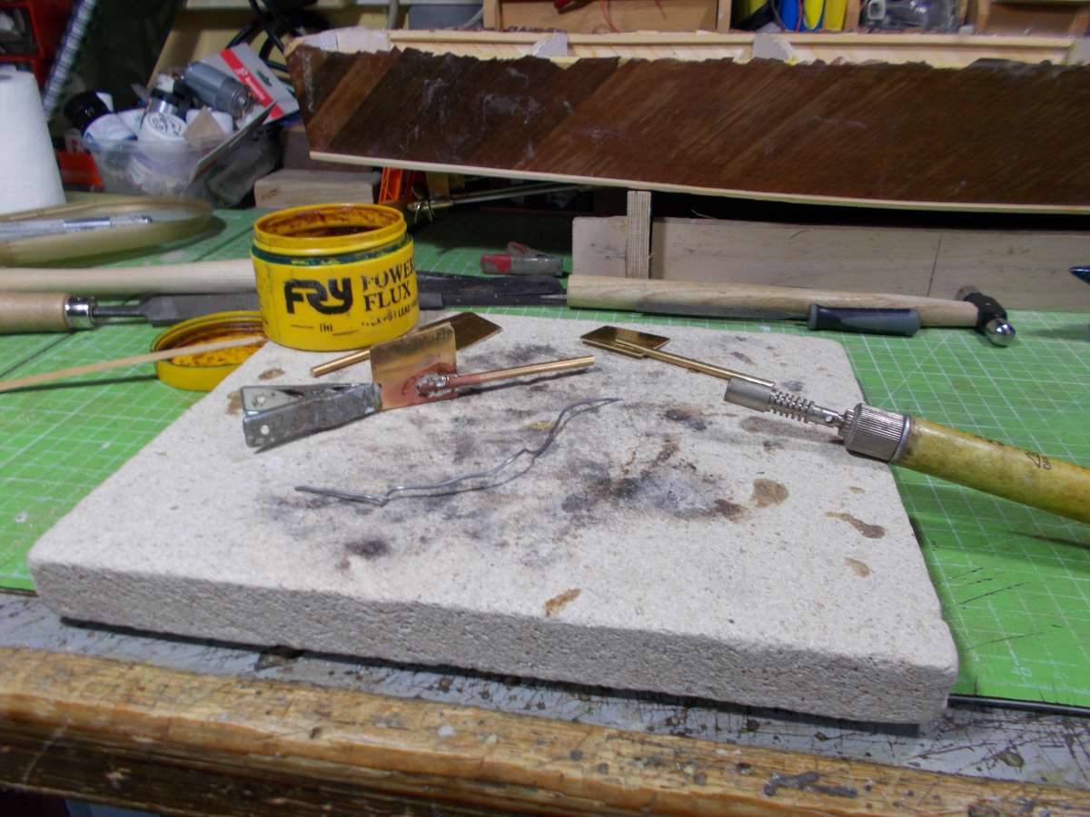
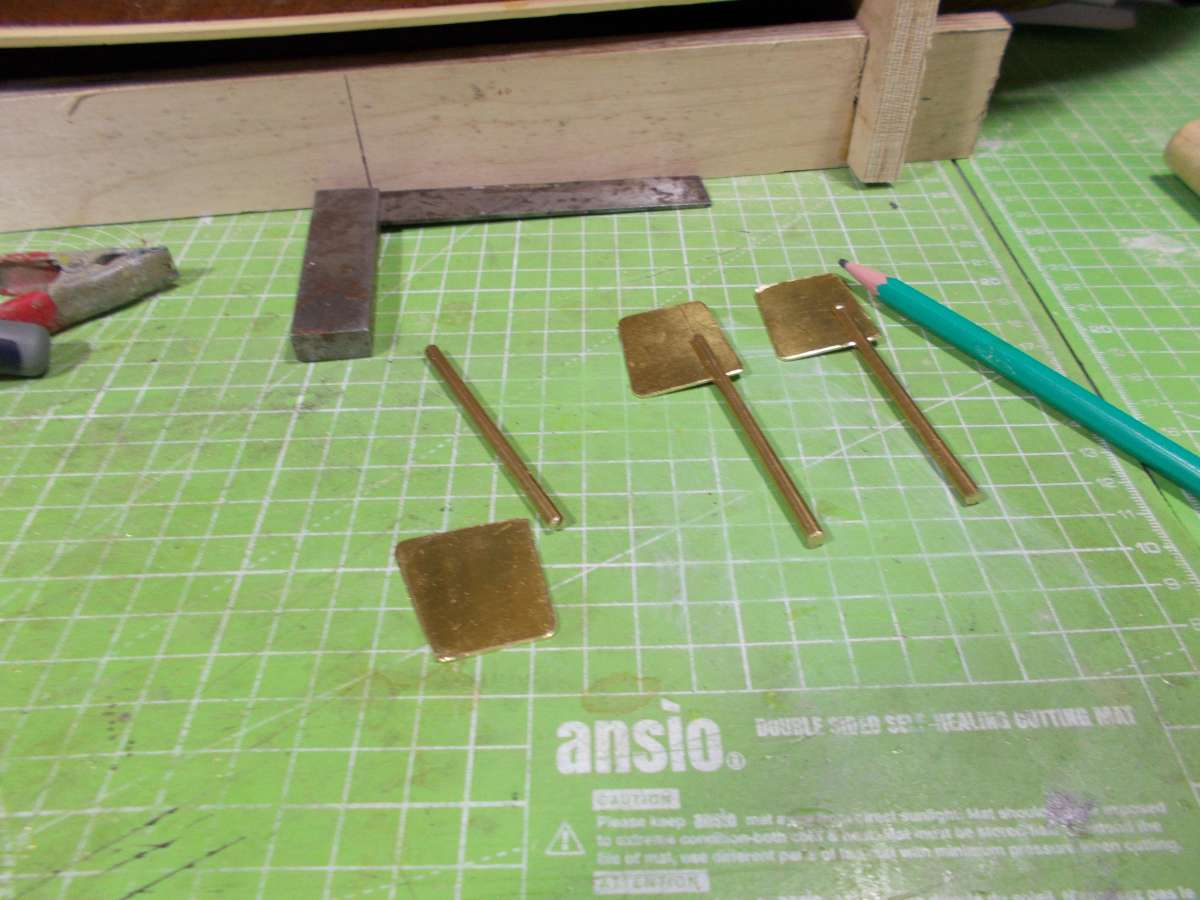
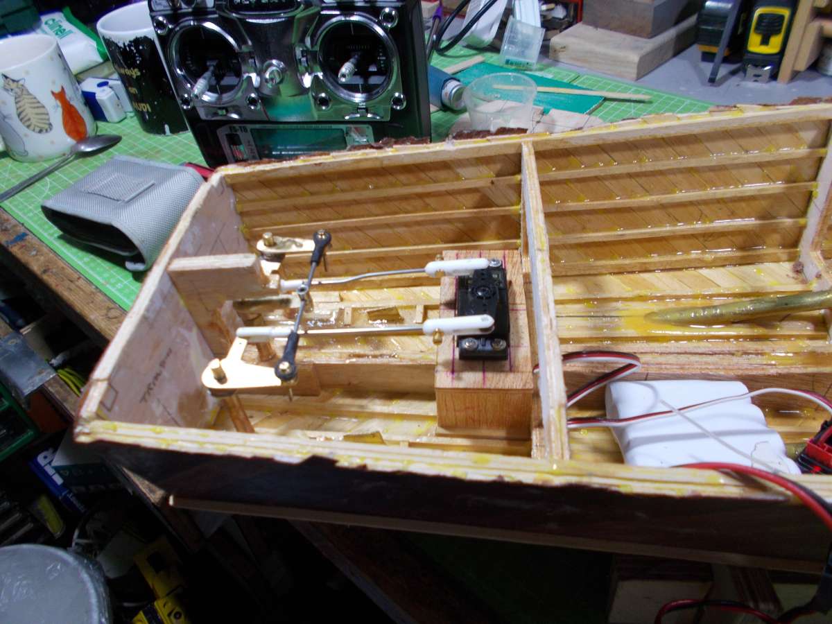
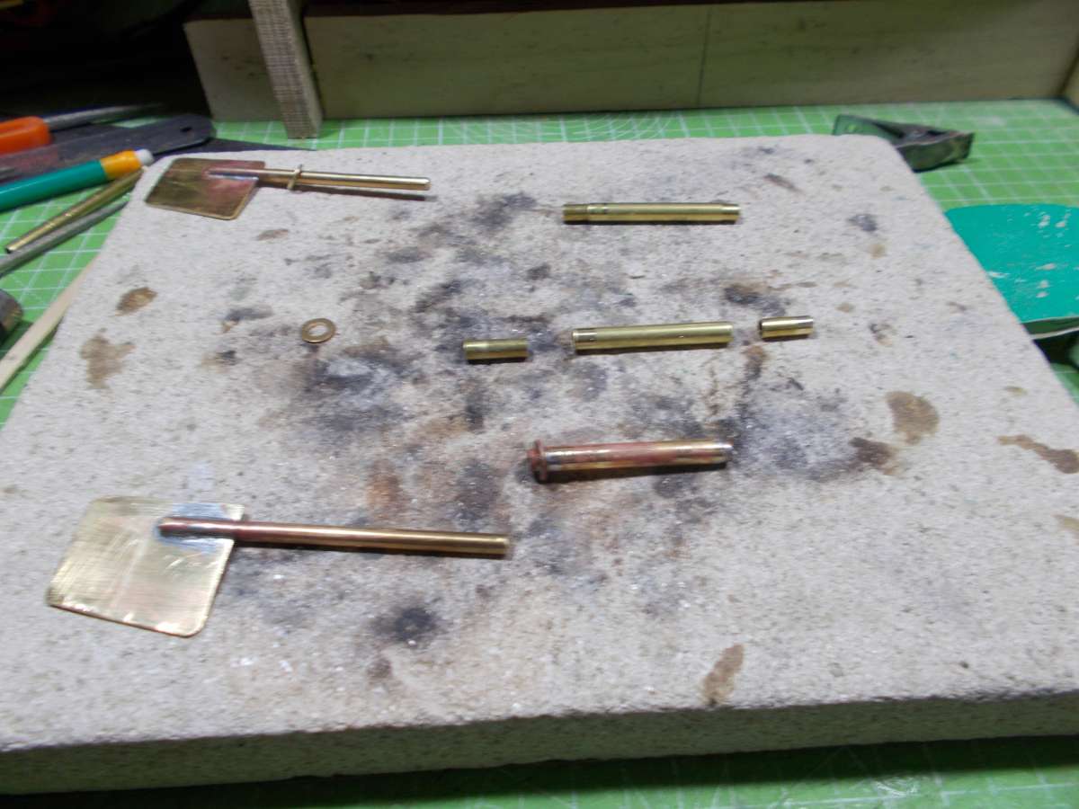
                                  further update:  been manufacturing the steering gear from sheet brass and tubing – the rudder shafts were made from 3mm diameter brass rod and the blades were 0.5mm thick brass sheet.  The internal linkage was made in a similar manner and those with the eagle eyes will notice I have had to put a ‘dog leg bend’ in one of the connecting rods due to the fact that the servo mount moved when it was being epoxied in.   It would have been a bit of a job to remove and replace.   Also the internals of the hull have been sealed with resin to prevent water absorbtion.

                                  JohnDSCN1910DSCN1907DSCN1913DSCN1914

                                  #127393
                                  Chris Fellows
                                  Participant
                                    @chrisfellows72943

                                    I see in the article Glynn mentions the situation with aircraft props as well but says that the forces are taken by the other bearing when used in a boat that they are not designed for. But I still contend that in a slow/relatively light model it’s not much of a concern, especially if accurately set up some of the force will be shared by the P bracket as long as it is fairly substantial.

                                    In my defence of forgetting to install a collar, one wasn’t supplied by Raboesch, though one is for the motor end of the prop shaft, but one of that size is far too big for the prop end.

                                    But while sourcing brass bits and pieces for making the rudder mounting on my Fisherman build I managed to find some small brass collars with 3mm bore which should do the job nicely!

                                    Prop Shaft

                                    #127395
                                    John W E
                                    Participant
                                      @johnwe

                                      hi there,

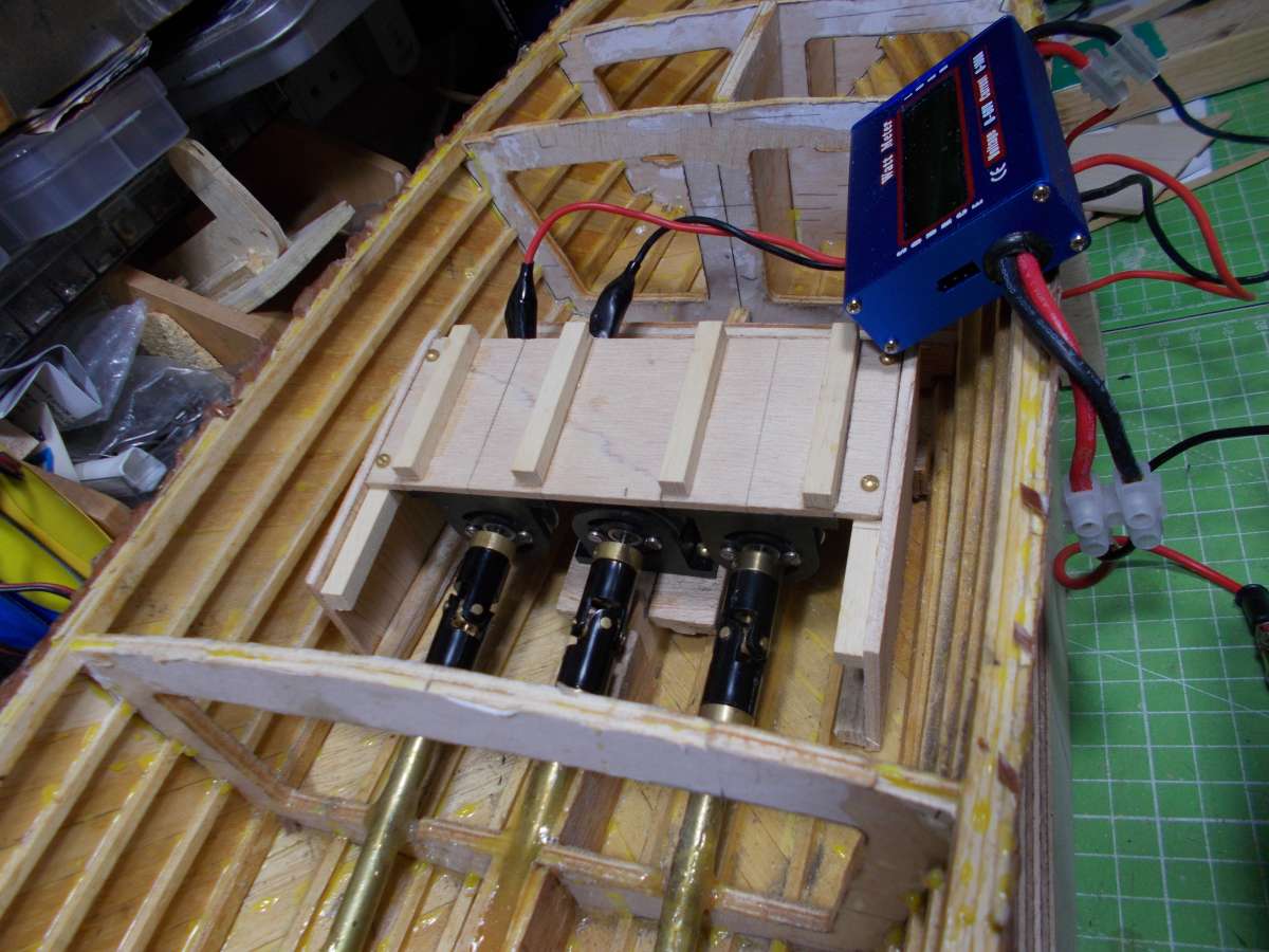
                                      Further update.   I have mounted the 3 motors into position.   The 3 motors are JP ProPower 480 .

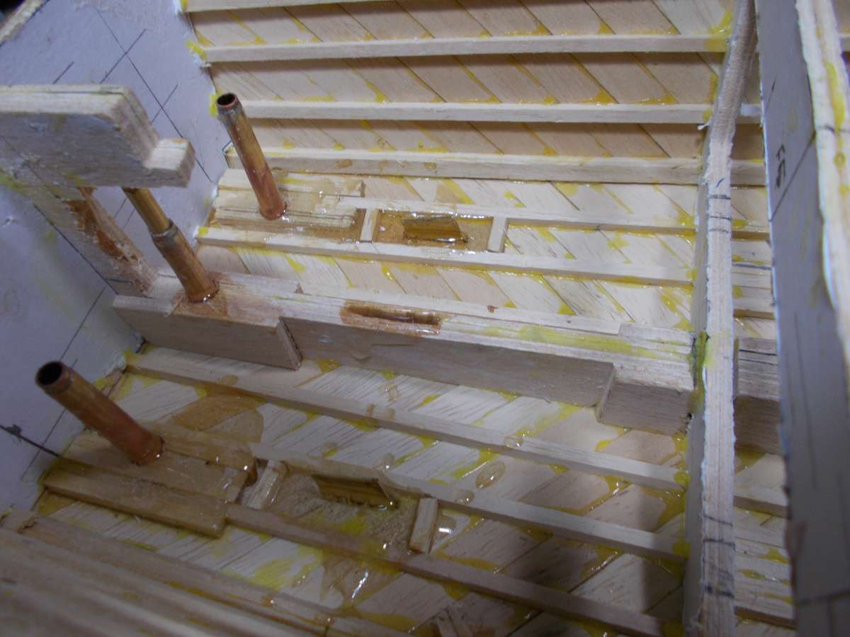
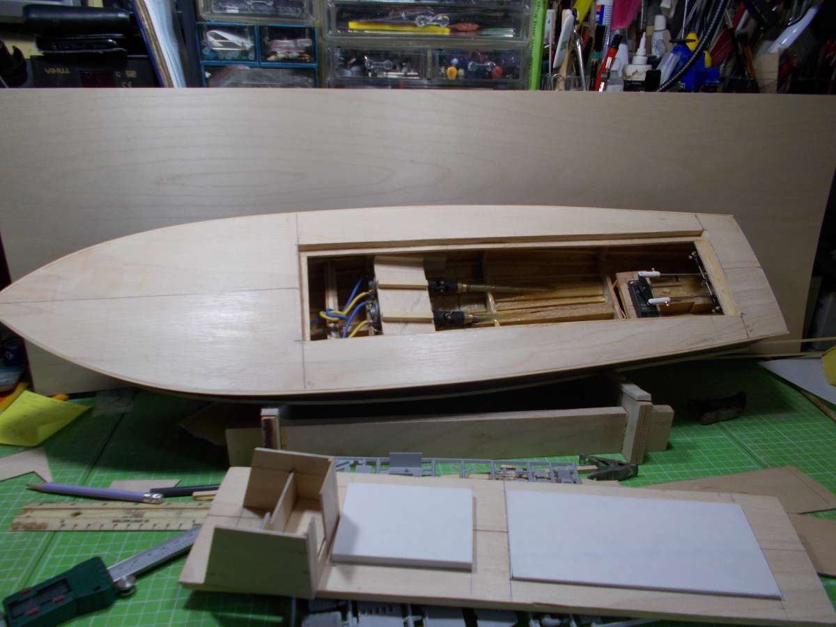
                                      Eagle eyes will notice that I have mounted the 2 outboard motors upside down, due to the fact of the lack of space between the 3 motors.   I am now busy lining up and doing an amp test to make sure that the amps are running as low as possible.   At the moment they are running at about 1.9 to 2 amps free running – still a little bit high which may be due to the grease I have used in the tubes. A bit running in may help.

                                      Also, an image I forgot to put on last time is the image of the assembly of the rudder tubes.

                                      fred

                                      DSCN1916

                                      DSCN1911


                                      #127474
                                      John W E
                                      Participant
                                        @johnwe

                                        time for an update …………….

                                        Been busy with other projects, eg fitting a new fan in the Crusader – so – just recently started back on this build of the MTB.

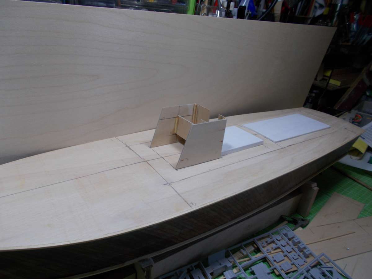
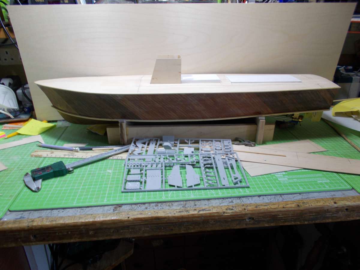
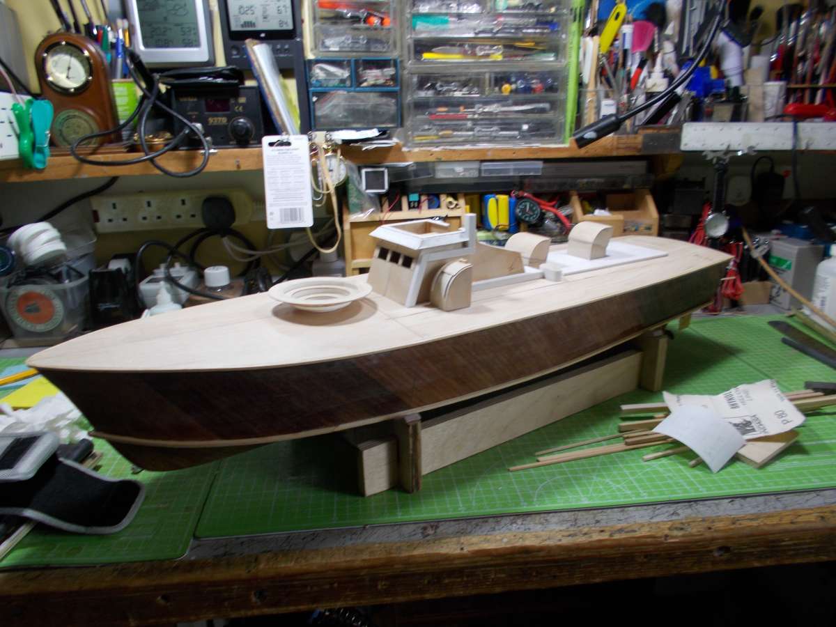
                                        Fitted the deck from 2 mm lite ply.

                                        At the moment the deck has had 3 coats of sand n sealer on.

                                        Now busy making the bridge, hatches etc and deck fittings.

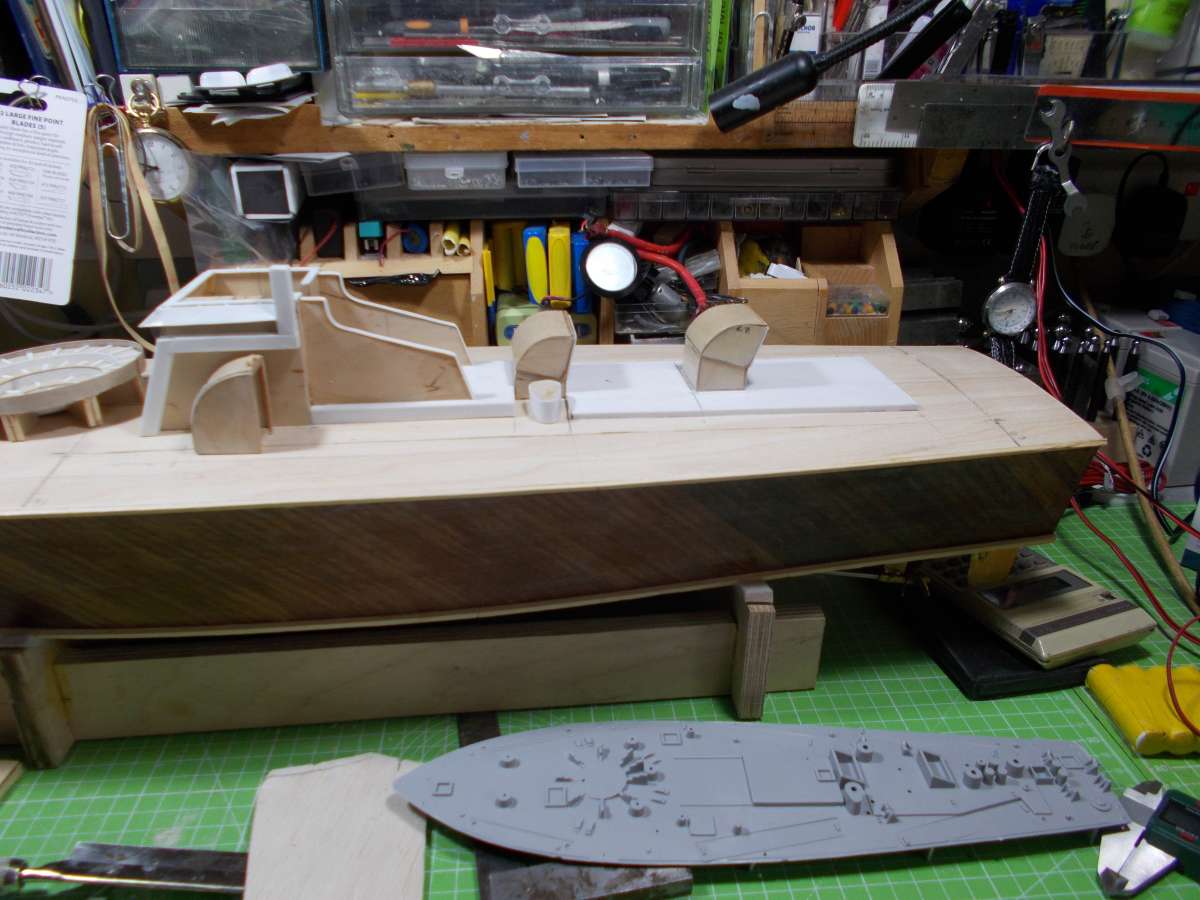
                                        What I am doing, is, I have an Airfix kit of the MTB – and – using that kit as a reference for fittings etc.

                                        The plan which was supplied in magazine was just supposed to be a stand off scale; I thought I would try and improve my model by using the kit as a reference – helping me to get some of the fittings nearer to scale.

                                        Also, I am using the late John Lambert’s book ‘Allied Coastal Forces’ as a reference.

                                        JohnDSCN1928DSCN1929DSCN1930

                                        #127478
                                        Richard Simpson
                                        Moderator
                                          @richardsimpson88330

                                          An excellent way of doing it John.  Many old kits leave a lot to be desired when it comes to fit and finish but the majority are fine as a basic representation of the real thing that can be measured and scaled up.

                                          #127544
                                          John W E
                                          Participant
                                            @johnwe

                                            hi there

                                            update once again – proceeding making more fittings – basically from Balsa/plywood and plasticard.  Things I have noticed now is that there is a lot of conflicting information with regard to the Airfix model and some of John Lambert’s books.  With regards to bridge layouts and so forth – there are slight differences.

                                            So, I am going to stick with following the Airfix model kit – one problem though I have just noticed – I think I will have problems locating the torpedo tubes because of the access hatch.  The torpedo tubes will sit half and half over the hatch and deck – so going to make the torpedo tubes either swivelling or detachable,

                                            JohnDSCN1933

                                            #127547
                                            Richard Simpson
                                            Moderator
                                              @richardsimpson88330

                                              Another one where magnets might be a useful solution John.

                                              #127574
                                              Philip Oxley
                                              Participant
                                                @inonowt

                                                Hi John.

                                                Nice to see your boat coming together.  Looks to me like your hatch is a really good fit.  Did you fill the grain of the deck before coating?  I think by it’s very nature, lite ply grain is very open.
                                                <p style=”text-align: left;”>In Barrie Griffin’s DVD accompanying the Sarik kit, he says he made his detachable and used dowels to locate the tubes.  Roofing bolts (without nuts) could be a solution which would add a bit of weight to hold them in position.  I notice you’ve fitted raised pads to the rear.  They’re not going to impact the fitting of the torpedo tubes are they?</p>
                                                Best wishes.

                                                Philip.
                                                <p style=”text-align: right;”></p>

                                                #127582
                                                John W E
                                                Participant
                                                  @johnwe

                                                  DSCN1935hi there Philip

                                                  The deck has had 3 coats of deluxe sand n seal, for the time being.  I will possibly give it another coat a bit later on in the build.

                                                  The engine hatch at the back will receive 2 cutouts to receive the torpedo tubes when I have finalised the position of them and also how I am going to locate them.

                                                  I still have a big debate as to how I am going to locate the tubes.

                                                  At the current time, magnets and pins seem to be the flavour of the month for me.   But, as they say, watch this space – it all could change.

                                                  John


                                                  #127588
                                                  Philip Oxley
                                                  Participant
                                                    @inonowt

                                                    Yes.  It is a case sometimes of making it up as you go along.  There have been times when I have come up with a plan, bought materials online, and before it’s delivered I’ve changed the plan and had to order different stuff.  Still, I think I’ve got enough of everything to make another model at zero cost.😂


                                                    #127609
                                                    John W E
                                                    Participant
                                                      @johnwe

                                                      hi there

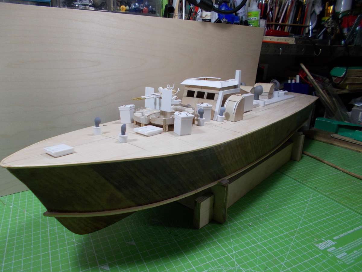
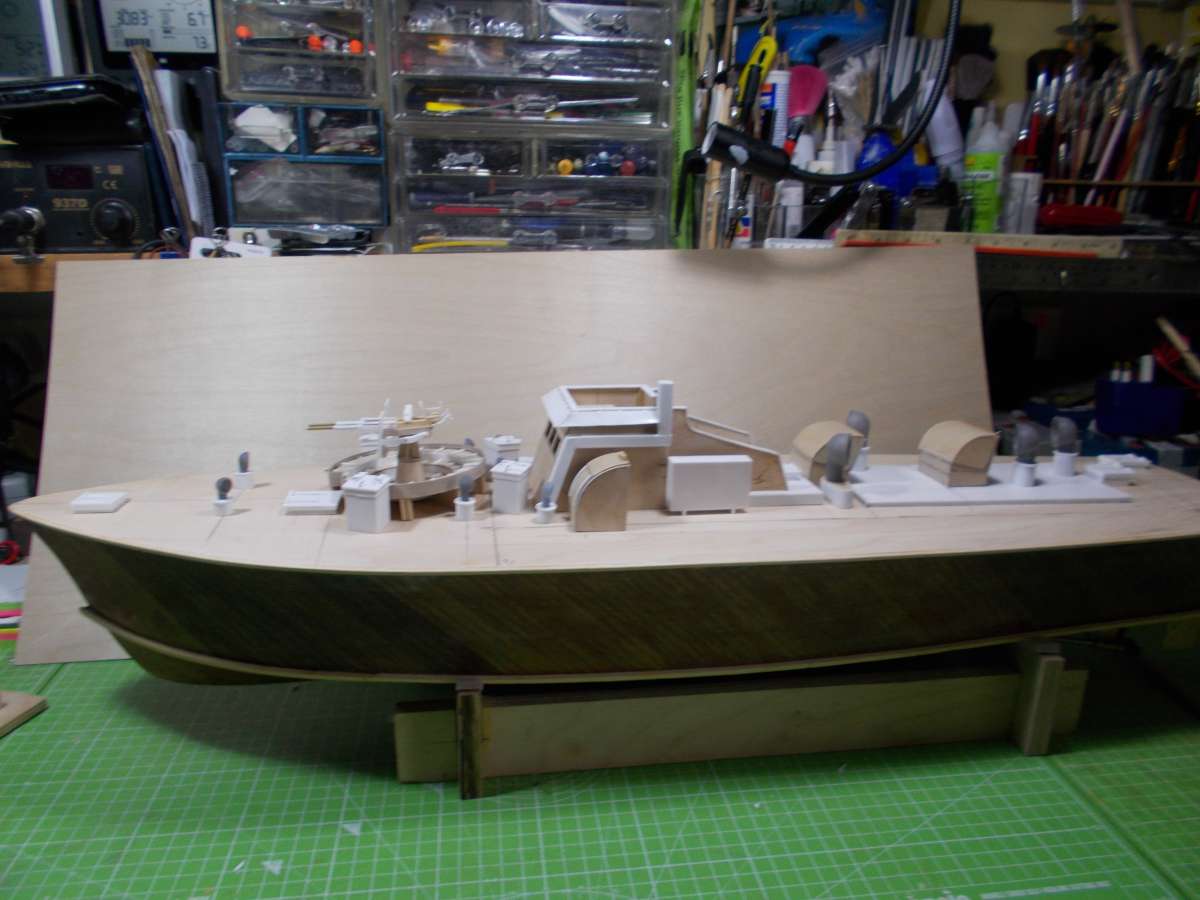
                                                      A little more progress – Ammo boxes made from square blocks of balsa, covered with plasticard.   3D printed air ventilators.   Ollerkon gun made from wood, plasticard and bits of brass tubing.   Now we need to make the torpedo tubes,   Might venture into doing a bit of paining of the model.

                                                      DSCN1940DSCN1941


                                                    Viewing 25 posts - 26 through 50 (of 55 total)
                                                    • Please log in to reply to this topic. Registering is free and easy using the links on the menu at the top of this page.

                                                    Code of conduct | Forum Help/FAQs

                                                    Latest Replies

                                                    Home Forums Beginners Topics

                                                    Viewing 25 topics - 1 through 25 (of 25 total)
                                                    Viewing 25 topics - 1 through 25 (of 25 total)

                                                    View full reply list.