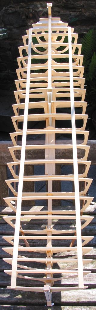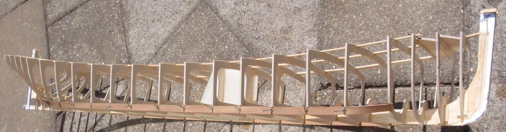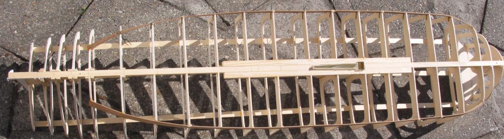

Spider J

Spider J

Home Forums Scratch build Spider J

  • This topic is empty.
Viewing 25 posts - 1 through 25 (of 201 total)
  • Author
    Posts
  • #6961
    Gareth Jones
    Participant
      @garethjones79649
      #50535
      Gareth Jones
      Participant
        @garethjones79649

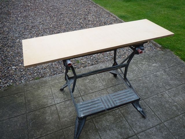
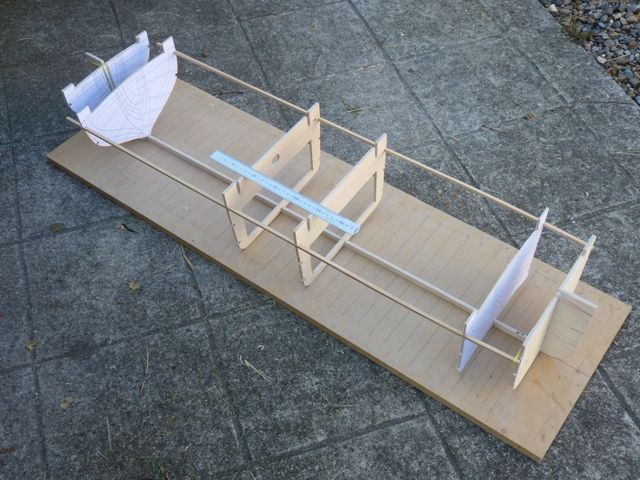
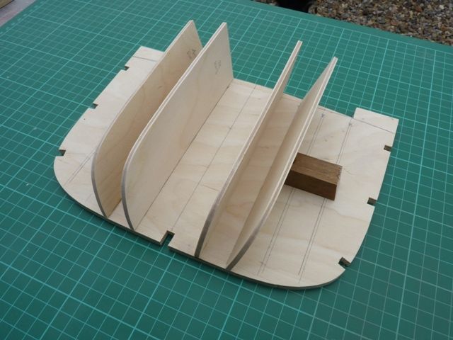
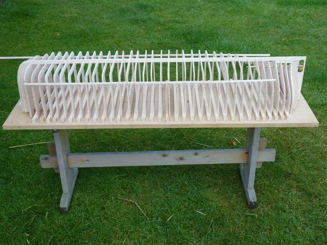
        This post marks the start of another epic building saga, although hopefully not as long as the Shemarah thread. The building board emerged from the workshop this week to be dusted off and have all the Shemarah frame positions sanded off.

        spider 1.jpg

        The next project is intended to be a double bill with the same basic hull built twice, consecutively to save time. I plan to finish the first of these as a Humber sloop and my wife Elizabeth is going to do the second one as a Humber keel.

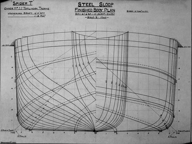
        We have been into the Maritime Museum in Hull this week and photographed the drawings of one of the last keels to be built on the Humber, Spider T, which was launched from Warren's shipyard in New Holland in 1926. It was built for Mr. J. J. Tomlinson of Thorne whose nickname was Spider. Because many of the boats had similar names it was common practice to add the owners initial at the end to differentiate, hence Spider T.

        Spider T is still sailing the waterways around the Humber, although not as a cargo carrying sloop. There is a link to its website here **LINK** However we are not sure yet whether to build the models as replicas of one of the surviving keels and sloops or just a generic model as they were when they were working vessels.

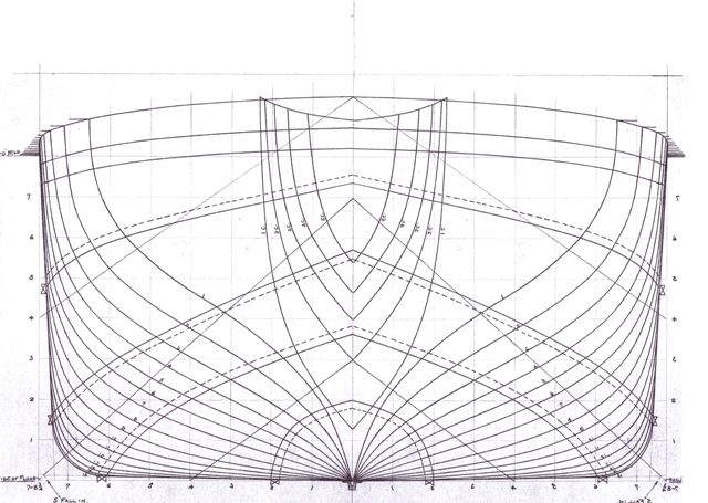
        The body plan lines fit on a single sheet of A4 paper at 1:16 scale. I will print a sheet off, flip the original, print that drawing and then cut both sheets in half. Two halves will then be swapped over and joined so I have one A4 sheet showing the full outline shape of all the forward frames and a second showing all the aft frames. These will then be scanned back into the computer and printed out to give an accurate 1:16 scale set of drawings which can be used as the templates for cutting the frames from 6 mm ply.

        spider 3.jpg

        The lines of sloops and keels were very similar and largely down to the choice of the owner. Sloops tended to have a longer 'run' which is the aft section that tapers from the rectangular box shape in the middle to the stern. This improved the handling qualities at the expense of some cargo capacity. Spider T has an exceptionally long run hull so should have the best possible sailing qualities. I am not too fussed about its cargo capacity, there should be plenty of space in the hull for all the 'gubbins'

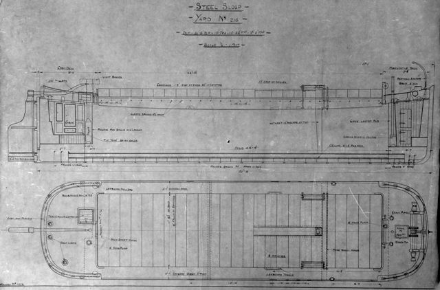
        Here a plan and elevation drawing of the hull

        spider 2.jpg

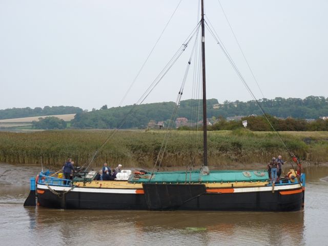
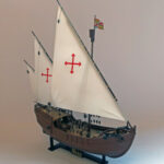
        For those of you who have trouble understanding drawings here is what the final model should look like. This is the Humber keel Comrade, also still sailing the local waterways.

        spider 4.jpg

        I have chose 1:16 scale as the biggest practical size for the model, which will be 46 inches long between perpendiculars, i.e. from the rudder hinge point to the prow. It will be about 48 inches high when rigged, but the mast will be able to be lowered as they were on the real ships. Sorry Bob, I am not going to make it 8 feet long.

        In addition to having fully working sails and lee boards the models will be motorised, as were most of the sloops and keels from the 1930's onwards. To push forward the frontiers of model boating I plan to try a brushless motor for the first time in a model boat. I do have what may be a suitable motor in a model aircraft in the loft. At some point I will have to get it out and see what size and rating it is.

        Thats all for now, hopefully progress will be fairly rapid over the next few months, unless some other interesting project take my fancy, or I get coerced into helping Elizabeth with her current project, the tea clipper Ariel.

        Gareth

        Edited By Gareth Jones on 19/07/2014 09:32:40

        #50536
        Bob Abell 2
        Participant
          @bobabell2

          All the best, Gareth and Elizabeth with your new model making venture

          If they are anything like the Shemarah build, they will be lovely!……Despite being on the small size…..lol

          Scale ribs we presume?……What choice of timber?……..Something exotic like Lime and Pear?

          Would be nice to see the models built simultaneously, then we could watch the fireworks at the same time?

          Pleased to read that you will be fitting motors….Very sensible

          Bob

          #50557
          Tony Hadley
          Participant
            @tonyhadley

            Gareth, I can only endorse Bob's comments about your Shemarah build. It was interesting to see the model built to such a high standard, and the rust detailing at the end added to the model's realism.

            Will be following the thread of this new build.

            Did Elizabeth finish the tea clipper, Ariel.

            #50558
            Gareth Jones
            Participant
              @garethjones79649

              Tony,

              Ariel is still work in progress. The radio gear and controls are fitted, the masts have been made, the deck has been planked and all the main deck components such as hatches and the cabin have been fitted. Elizabeth has just fitted the bulwarks but they still need capping rails and some stiffners. There is still a lot of work to do and I do not want to post any photos, as the model will probably be the subject of a Model Boats article some time next year. However it will be on display at Haydock Park next month if you want to have a look at the progress so far.

              Gareth

              #50571
              Gareth Jones
              Participant
                @garethjones79649

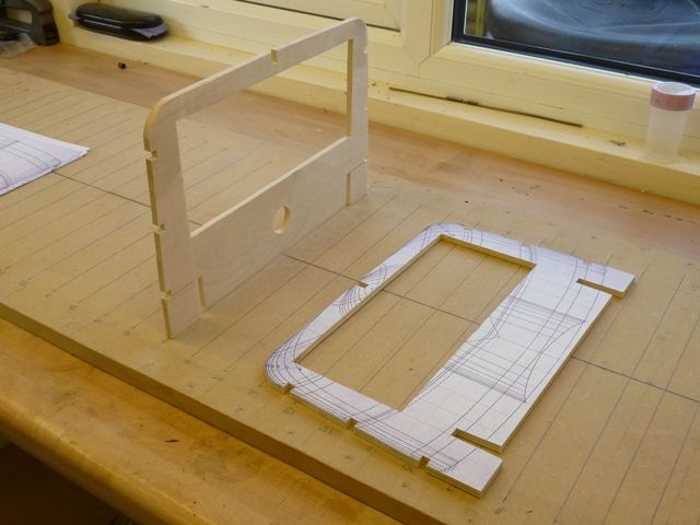
                The frame sections have now been created as described above and here is a photo showing all the rear frames. I print them out on A4 sheets using Canon Easy-Photoprint, using the trimming tool to get them the right size. They only just fit on to the paper so its easy to judge the right level of magnification and get them all the same size, which is 290 mm across the extreme edges at the top.

                spider 5.jpg

                I have cut the first couple of frames from a spare bit of 6 mm ply, as shown below.

                spider 6.jpg

                I have made a few basic decisions so far but the design is still evolving. I have done a rough calculation of the weight of the model. A fully loaded keel could typically carry 80-100 tons of cargo and weighed around 30 tons, say a typical weight of 120 tons or 120 x 2240=268800 pounds. Since the model will be 1:16 scale the weight of the model should be 268800 / 16 x 16 x16 = 65 pounds approx. That is about the same as Shemarah so it will need removable ballast to be practical and, like Shemarah will have a built in carrying handle, hence the hole in the frame above.

                Most of the remaining frames will be cut from 4 mm ply. However while the outside shape of all the frames is defined, the inside shape has yet to be decided. I plan to use the cargo hatches as access and the hold as working space in the model so there should be plenty of room for the control gear and ballast. However a major decision is should the model have an external removable keel, or can I get away with just ballasting it along the lowest point of the almost flat bottomed hull. It will not carry as much sail as a Thames barge so maybe some advice from one of their experts might help – Kim?

                Gareth

                Edited By Gareth Jones on 22/07/2014 09:10:38

                #50582
                Kimosubby Shipyards
                Participant
                  @kimosubbyshipyards

                  Evening squire,

                  just spotted that question you posed, neatly done, and expert???

                  You witnessed a thames barge under extreme conditions at Onchan Park, when everyone (me included) expected a full capsize in those 20+knot gusts. You also know that I had let all sails fly and that I had on the small ballast (about 2.5lbs) about 6 – 8 inches below the hull bottom.

                  She stayed above water, though level with it on her beam ends, and because the lead battery was securely fitted on the keelson, she righted and I was able to sail her back in without any damage nor water ingress. A change of attire was almost needed though and yes, the pictures are on the web via our website.

                  The Humber keel has, as you say, much less sail, and a much shorter mast, of which there is only one, and only one sail to worry about. It is quite easy to add external ballast should it be needed, and in my opinion and if it were my build I'd have the option for it. BUT saying that, from your calculations above it would seem that you intend to float to near full capacity. Our thames barges are used for "racing" so are empty and sail as "in ballast" so the need for a keel. She'll probably then get away without external ballasting provided you get the mass low in the hull. I expect these Humber keels were as "stiff" in sailing terms as the thames barges, having all the weight low will make her stiff. They certainly operated out to sea so must have been weatherly too.

                  I'll have my new barge at Haydock, we'll have plenty of time to chew the cud, after all, who wants to come and see us old "Vintage Crew" with sailing stuff all about us?

                  A point to note as well, and I know you know but its important to get it in discussion, and thats scale and dimensions. A halving of scale for length is x 0.5, where as for area it's x 0.25 and for volume it's x 0.125. That's for each halving, so at 1:16 you have halved 4 times. So the sail area is a lot less, the rudder area severely reduced and the hull volume dramatically lost all in relation to each other. You will most certainly need to extend the rudder to get grip, and although you intend to operate the leeboards, their area will be too small to be effective at the scale, and making them bigger will ruin the actual visual impact. Its another reason we instal a keel – to stop leeway and permit the rudder to give some influence to direction (when as we all know its the sails that steer the boat being set for the required heading, the rudder is used to stop the stern crabbing away or when the engine is on.)

                  On that point I'll dig up an interesting photo of a barge under full sail and making her course, but the rudder angle is not what you'd expect. Remind me to bring the old barge DVD's too.

                  There, if you'd a pipe you could now smoke that, see you soon, Kim.

                  #50642
                  Amy jane September
                  Participant
                    @amyjaneseptember49770

                    Another interesting project, and no doubt will be a joy to follow!

                    All the best to Elizabeth, and her clipper project too.

                    #50751
                    Gareth Jones
                    Participant
                      @garethjones79649

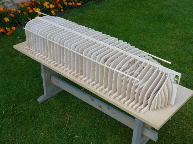
                      Spider J's bricklike shape has begun to emerge from the sheets of 4 mm plywood that arrived last week.

                      spider 7.jpg

                      I have done some research into brushless motor options and based on advice on the forum I have ordered a Turnigy 3548/6 as a first guess. This is rated at 790Kv, i.e it will do 790 rpm per volt applied so on 12 volts should do 9480 rpm and be able to deliver around 460 watts. Its 35 mm in diameter and 48 mm long and will allow the propshaft to be mounted low down in the hull of the model.

                      Based on some photos I have of various keels and sloops it appears that a typical propeller was around 30 inches diameter and had 4 blades. At 1:16 scale that translates into about 45 mm in diameter. The nearest I have in the database of models I have tested is my TID tug which has a 55 mm 4 bladed propeller and a Springer that I have run with a three bladed 40 mm propeller

                      The TID does 2140 rpm or 52% of the motor free running speed using a Graupner 720 BB torque with an input power of 54 watts.

                      It also does 3150 rpm or 48% of the motor free running speed using a Graupner 900 BB torque with an input power of 145 watts

                      The Springer does 3250 rpm or 45% of the motor free running speed using a Graupner 500E with an input power of 31 watts

                      Hopefully the brushless motor should be able to spin the 45 mm propeller at around 5000-6000 rpm or somwhere in the range of 50-60% of the free running speed. I am expecting that for the majority of the time Spider will be powered by its sails rather than the motor so there is no requirement for long periods at high powers, just the occasional blast to get the model out of trouble. My intention is to temporarily adapt my TID tug as a testbed for the brushless motor. If the results are interesting or helpful I might write them up in an article for the magazine – Turbocharging a TID tug is the provisional title that has come to mind. The information might help illuminate the dark art of matching brushless motors and propellers.

                      Now its back to the workshop for another session of cutting frames from 4 mm ply. So far I have made 9, only another 27 full width frames to go plus about a dozen canted frames at the extreme front and back ends.

                      Gareth

                      Edited By Gareth Jones on 28/07/2014 07:59:40

                      #50752
                      Bob Abell 2
                      Participant
                        @bobabell2

                        Gareth

                        9 frames plus 29 frames comes to 36 frames!

                        Did you not consider carving the hull from a solid block of wood?…..As there ain`t much fresh air left?

                        36 curved frames would look nice, but 36 bulkheads……Sharp intake of breath!

                        Looking forward to the build

                        Bob

                        #50753
                        Gareth Jones
                        Participant
                          @garethjones79649

                          Bob,

                          There's plenty of fresh air in Spider J. The front three frames are full bulkheads, there are two in the middle and about half a dozen at the back end. All the rest are U shaped 4 mm ply. On the real Spider the centre section frames are spaced 20 inches apart which equates to about 32 mm on the model. I will put another photo up tonight when I have cut out a few more.

                          Gareth

                          #50986
                          Gareth Jones
                          Participant
                            @garethjones79649

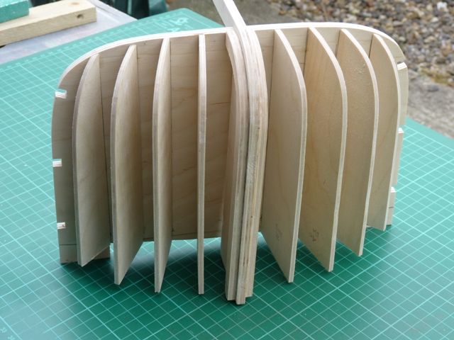
                            Progress has been quite rapid on Spider J over the last week. I began to cut out and shape the canted frames which form the shape of the bow section.

                            spider 8.jpg

                            Initially these were just tacked in position with superglue. The edge which meets the first frame was angled on a disc sander and supported with a short piece of square section timber to hold it in place while the glue set. When all the sections had been added I checked that the edges all lined up on the profile where the skin will be attached.

                            spider 9.jpg

                            Superglue was then run down all the edges to finally glue the canted frames on to the main front frame.

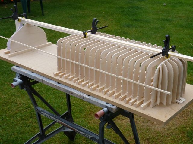
                            Next it was into mass production of the 4 mm thick frames that make up most of the hull. These have come out muct more accurately and consistently than the ones on Shemarah. The reasons for the improvement are partly down to the production of the templates on computer prints, rather than tracing them off the plan by hand. I also now have the disc sander so it is much easier and quicker to trim the edges of the frames accurately and squarely rather than by hand sanding with a block and abrasive paper.

                            spider 10.jpg

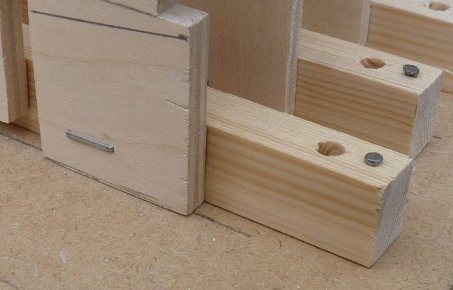
                            I have also made a couple of changes to the way the frames are attached to the battens that fix them to the building board. On Shemarah I screwed the frames to the battens and then screwed the battens to the board. There were two problems with this. One was that when I came to screw the battens down on the MDF building board it tends to lift the MDF and the batten does not sit square and flat on the board. Hence it was necessary to remove the screws and effectively countersink the screw hole in the board, all time consuming and not helpful to getting the batten and frame in the right place. The second problem was that when it came to removing the battens from the frames, after the completed hull was taken off the board, it was really difficult to get to the screw heads because the frames were so close together. They are even closer on Spider J so an alternative method has been used.

                            spider 11.jpg

                            Firstly the frames have been stapled to the battens using 8 mm staples, good enough to hold them together during the build but easy to prise apart afterwards. Secondly the battens have been pinned to the board using panel pins, again good enough to locate the battens on the board but much quicker to fit and easier to get the frames accurately lined up on the building board. Hence progress has been very quick and, as I write I just have three more frames to cut out and attach. However these will need some adjustment as the plans show Spider T before she was fitted with a motor and propeller so there is some reprofiling required just forward of the propeller.

                            The brushless motor, speed controller, propshaft and propeller have all arrived so this week I am going to concentrate on testing the instalklation of the motor and proposed propeller in my TID tug before finally deciding on the installation in Spider J.

                            Next weekend we are off to South Ferriby on the other side of the Humber from where we live. The Humber Keel and Sloop Preservation Society are holding an open day to celebrate the centenary of Amy Howsons original launch back in 1914. She is one of the preserved sloops and there will be a gathering of keels and sloops in Ferriby sluice so there should be some good opportunities to get some usefull photographs and Spider J might also go along for a day out.

                            Gareth

                            #51029
                            Kimosubby Shipyards
                            Participant
                              @kimosubbyshipyards

                              Hi Gareth,

                              you've lots more frames than I used for the Lady Daphne. Here's a quick view from all angles, you'll note in the "fish eye view" that I had already cut the slot for the keel and positioned the keel box too (profile image). And, for barge construction we find it easier to frame upright, as they would have been built, secure the frames with "runners" and remove from the building board before any planking.

                              No motor in her, and if there ever would be, it would be positioned on the stern quarter, port side of the stern post.

                              She'll be good and strong.

                              Kim

                              tbladydaph_ (014).jpg

                              Frames viewed from above

                              tbladydaph_ (015).jpg

                              Frames in profile

                              tbladydaph_ (018).jpg

                              Fish eye view.

                              #51048
                              Gareth Jones
                              Participant
                                @garethjones79649

                                Hi Kim,

                                You could be right about the number of frames. Every time I go into the workshop I see the structure of Spider J sitting on the workbench in front of me. The artist in me thinks it's a thing of perfect symmetry and beauty, it could be the skeleton of a whale sitting there. The engineer in me thinks it has twice as many frames as required and I should take half of them out.

                                spider 12.jpg

                                spider 13.jpg

                                After some thought last night, I have just about decided to remove 11 alternate frames from 12 to 32 in the centre section of the hull. They would not be totally wasted as they could be recycled into the frames for a Humber keel as the next potential project.

                                I am still considering making provision for a keel slot like you have in your Thames barge Kim. What's the purpose of the bigger square section at the front of the slot – is it part of the keel or the location of the mast?

                                Today its back to motor testing, it should be exciting, has anyone ever seen a Springer tug with a 425 watt motor?

                                Gareth

                                #51049
                                Bob Abell 2
                                Participant
                                  @bobabell2

                                  Hello Gareth

                                  Don't be hasty!

                                  The multitude of formers,makes your model look special and true scale and commands respect!

                                  With less formers, your model will recede back into the nondescrpt modelling gloom?

                                  Food for thought for the discerning modeller!,

                                  Just my personal opinion

                                  Bob

                                  #51050
                                  Dave Milbourn
                                  Participant
                                    @davemilbourn48782

                                    Today its back to motor testing, it should be exciting, has anyone ever seen a Springer tug with a 425 watt motor?

                                    >1/2BHP?? Open the taps and you'll not see it for long, Gareth. They are noted for going bow-down when power is applied!

                                    Ref Spider J frames, I can see where the engineer in you is coming from but now you've plotted, cut and fitted them why take them out again? For once I agree with Bobbable.

                                    Dave M

                                    #51059
                                    Kimosubby Shipyards
                                    Participant
                                      @kimosubbyshipyards

                                      Gareth,

                                      now they're in leave 'em be! The configuration looks like an old cast iron radiator from my school days.

                                      The square hole in front of the keel box is a mast box IF the mast penetrated the deck, but on a barge the mast steps in a tabernacle on top of the deck and can then be lowered by swivelling about the lower mast bolt. I've used a keel box from a yacht set-up because I had one.

                                      I find creating the slot before planking enables the builder to get it supported and sealed whilst it can be seen and readily accessed.

                                      I tried a 700 in a springer with a 7.2 pack, as DM says, she just went nose under, so I came back to the 545 on the same pack and decreased the throttle range to 80%. She's still speedy, but does not bury the head so much, and I've fitted wash boards across the bow too. Our Jason tried a 700 with an 11.2 Li-Po totally wasted and awash……….

                                      Kim

                                      #51073
                                      Gareth Jones
                                      Participant
                                        @garethjones79649

                                        It looks like the popular vote is to leave all the frames in so that's what I will do.

                                        Motor testing went very well. I plan to write a short article for the magazine, Paul Freshney permitting, so I won't include all the details here. However in summary, the chosen motor was not up to driving a 55 mm diameter 4 bladed prop in my TID tug. The motor reached its 40 amp limit well before full throttle.

                                        However it was very well matched to the 45 mm prop chosen for Spider J. At full throttle it pulled just over 25 amps, around 290 watts and generated around 3200 grms of static thrust. If you wonder what how fast a Springer goes with that much power the video below should whet your appetite.


                                        Edited By Gareth Jones on 07/08/2014 20:51:09

                                        Edited By Gareth Jones on 07/08/2014 20:59:49

                                        #51074
                                        Gareth Jones
                                        Participant
                                          @garethjones79649

                                          Now that I have satisfied myself the video is working I should add the Springer was ballasted to be a bit tail heavy on the off chance that it decided to nose dive and do a submarine impression, Elizabeth was driving, and I took the video.

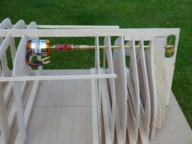
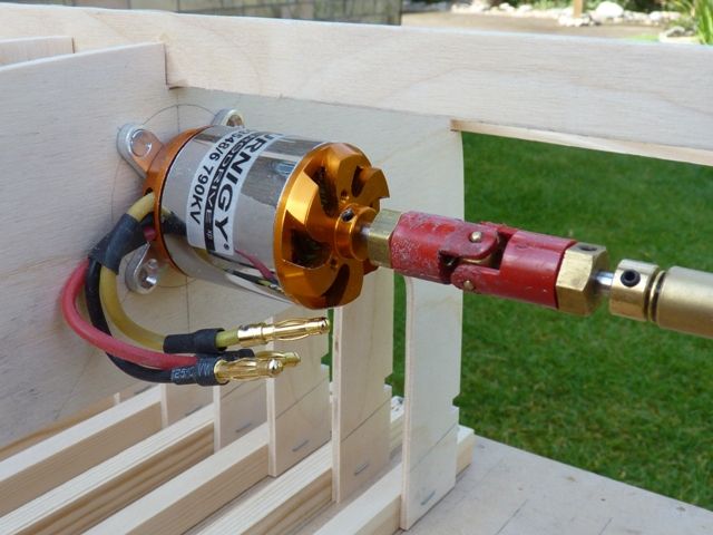
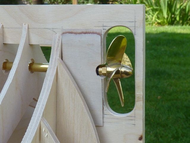
                                          The motor installation in Spider J has been trialled in advance of the testing and looks pretty good.

                                          spider 14.jpg

                                          spider 15.jpg

                                          spider 16.jpg

                                          The next step is to reprofile the last few frames so that the planking will meet the skeg ahead of the propeller. The frame shapes used in the build were drawn before Spider T was fitted with a motor, i.e. when it was just a sail powered sloop.

                                          Gareth

                                          #51087
                                          Bob Abell 2
                                          Participant
                                            @bobabell2

                                            Hello there Gareth

                                            Looking at your Brushless motor set up……Something is telling me that the flexible coupling is not right for this application?

                                            Haven`t got a good reason, but a solid coupling may be better?

                                            Bob

                                            #51093
                                            Gareth Jones
                                            Participant
                                              @garethjones79649

                                              Hi Bob,

                                              I dont know of any reason why the flexible coupling is not right for the application. The installation is identical to all my other models with the prop shaft as straight and true with the axis of the motor as I can achieve. At the moment the propshaft sleeve is a loose fit at frame 6, where it exits the cargo bay and in the skeg at the aft end. When I finally come to glue the shaft in, after all the frames are fixed in place, I will line up the motor shaft and prop shaft with a rigid coupling. The flexible coupling allows for any small discrepancies and also acts as a weak link in the power train if anything jams at high speed.

                                              I don't think a brushless motor is any different from a brushed unit and should not be fitted with a flexible coupling. During the tests on the motor in my TID tug, the peak input power to the motor was 425 watts and allowing for the motor efficiency, I guess the coupling in the picture was transmitting close to 1/2HP to the propeller at the time.

                                              You will need to come up with a good reason for me to leave the flexible coupling out.

                                              Gareth

                                              Edited By Gareth Jones on 08/08/2014 15:49:23

                                              #51118
                                              Kimosubby Shipyards
                                              Participant
                                                @kimosubbyshipyards

                                                Gareth,

                                                I was curious about the shaft being through the stern post and deadwood, but all the images I can find do, indeed, show the screw central on the stern. Like you I always have at least one flexible coupling. As well as your reasons, it also makes it easier to get the motor out if needs be.

                                                Here's a pic what I like – but you''ll have to get Elizabeth making barges a plenty so's you can match it! Good job the winds from astern, and has that keel, in the fore ground left, hit the dinghy ahead him? And I note, they are racing empty……….

                                                Kimmo.

                                                keel-race.jpg

                                                Edited By Kimosubby Shipyards on 09/08/2014 14:51:24

                                                #51119
                                                Gareth Jones
                                                Participant
                                                  @garethjones79649

                                                  Hi Kim,

                                                  That was a coincidence. I can't remember ever seeing that picture before today. This morning we went to South Ferriby to see the gathering of keels and sloops to celebrate the sloop Amy Howson's 100th birthday and the picture was on display inside her hold.

                                                  Gareth

                                                  #51120
                                                  Kimosubby Shipyards
                                                  Participant
                                                    @kimosubbyshipyards

                                                    do-do-do-do do-do-do-do do-do-do-do etc spookey or what?

                                                    Tell me you made up that place name, South Ferriby? Where ever, yet you say you've been there!

                                                    See youse soon, Kim

                                                    #51121
                                                    Gareth Jones
                                                    Participant
                                                      @garethjones79649

                                                      Kim,

                                                      What's so spooky about South Ferriby, its a real place and we were there this morning.

                                                      Gareth

                                                    Viewing 25 posts - 1 through 25 (of 201 total)
                                                    • Please log in to reply to this topic. Registering is free and easy using the links on the menu at the top of this page.

                                                    Code of conduct | Forum Help/FAQs

                                                    Latest Replies

                                                    Home Forums Scratch build Topics

                                                    Viewing 25 topics - 1 through 25 (of 25 total)
                                                    Viewing 25 topics - 1 through 25 (of 25 total)

                                                    View full reply list.