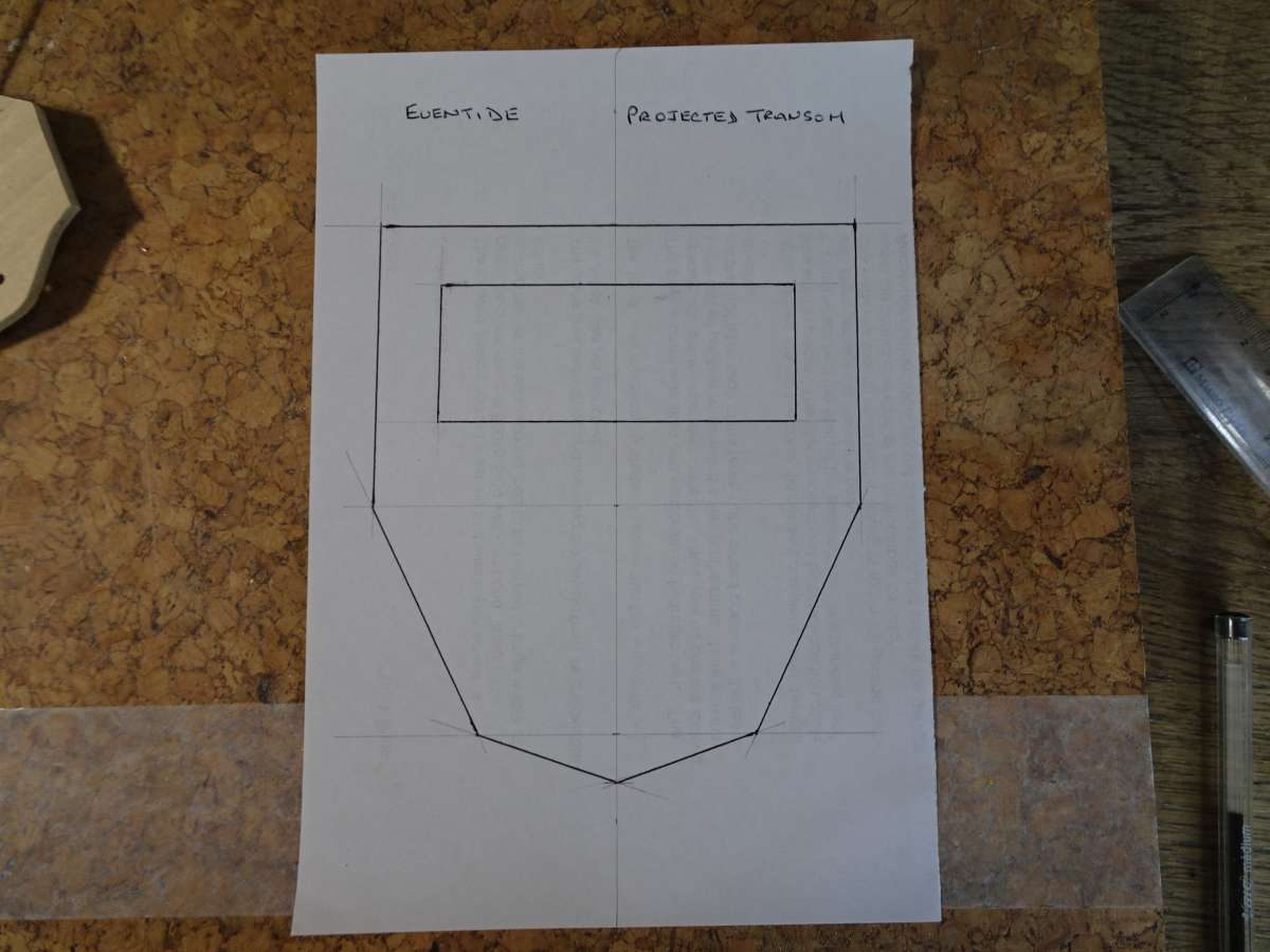
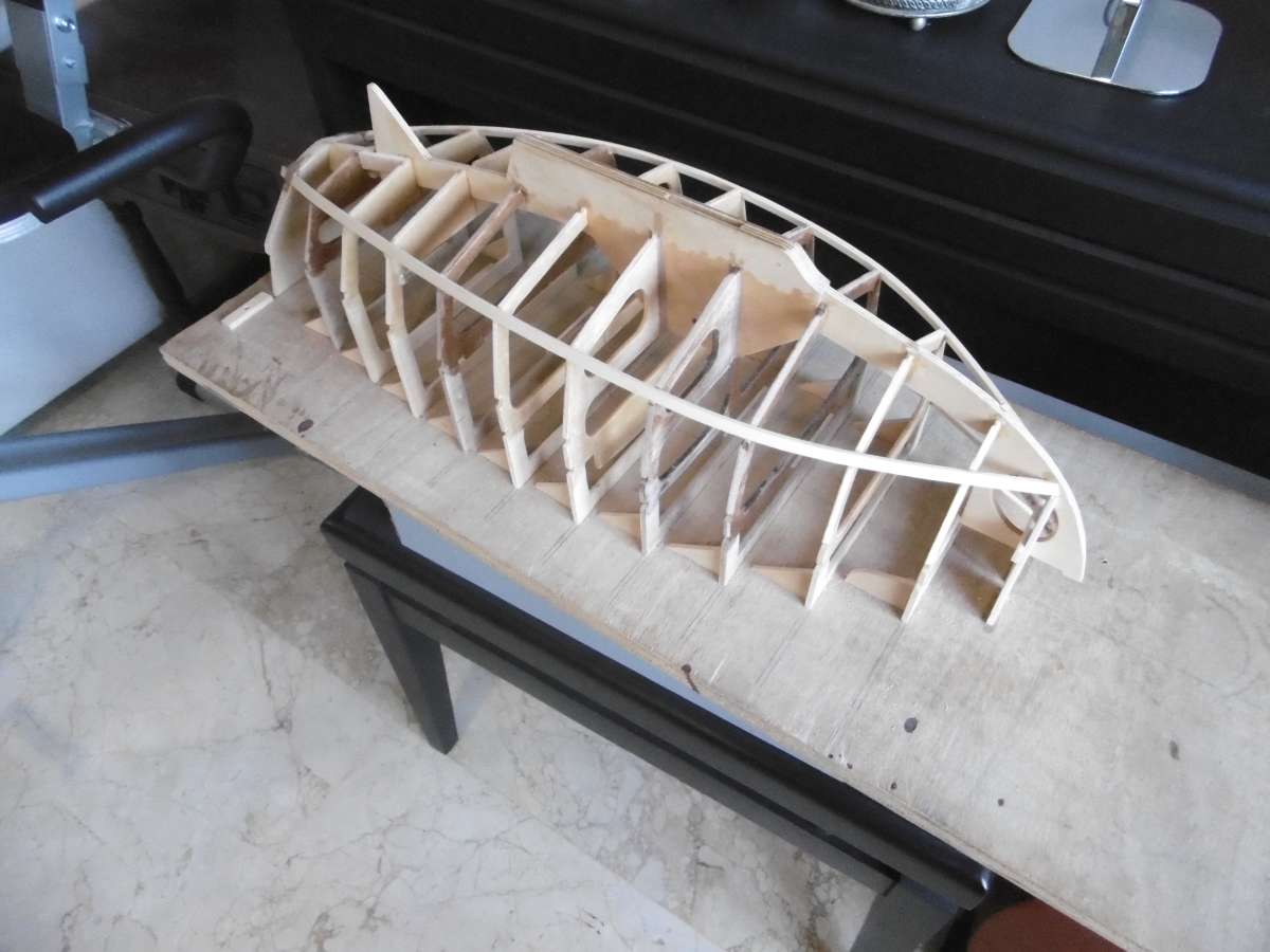
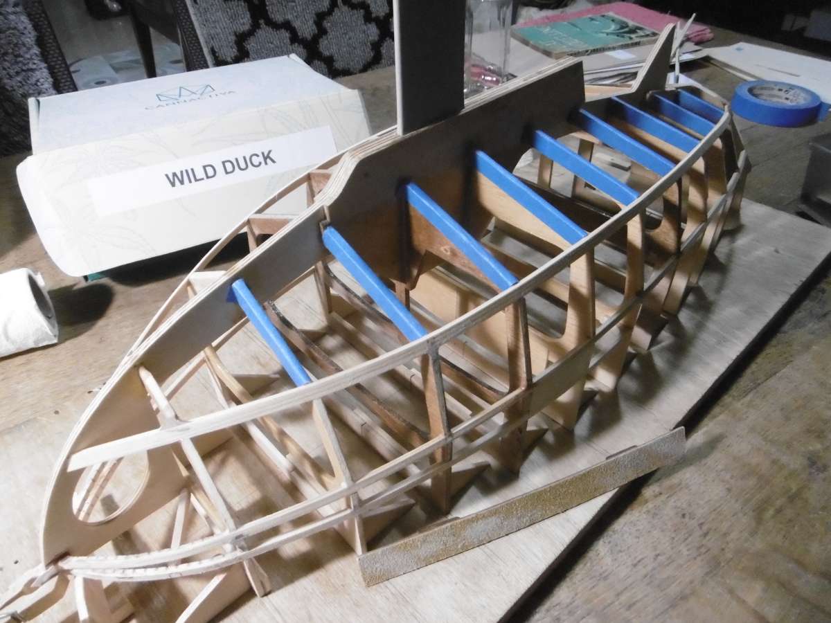
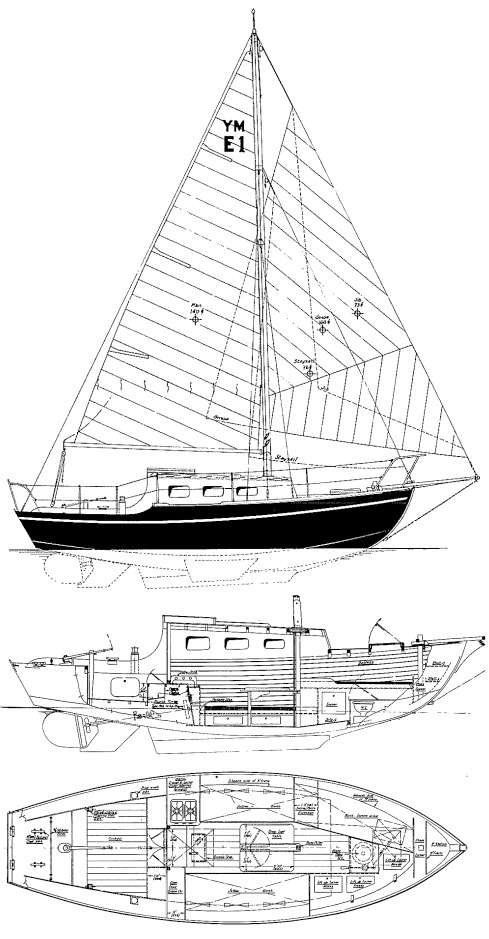
Wild Duck meets Eventide
Wild Duck meets Eventide
- This topic has 80 replies, 7 voices, and was last updated 1 month, 1 week ago by
 Tim Rowe.
- Please log in to reply to this topic. Registering is free and easy using the links on the menu at the top of this page.
Code of conduct | Forum Help/FAQs
Latest Replies
-
- Topic
- Voices
- Last Post
-
-
Lost article
Started by:
Karl Marforio 1 in: All things floating
- 2
-
21 hours, 7 minutes ago
 Colin Bishop
-
Todays Boating
1
2
…
214
215
Started by:
 ashley needham
in: All things floating
ashley needham
in: All things floating
- 86
-
23 hours, 22 minutes ago
ashley needham
-
Wivenhoe Lass – Fishing Boat – Scale 1/12th
1
2
Started by:
 Ray Wood 3
in: Scratch build
Ray Wood 3
in: Scratch build
- 6
-
2 days, 3 hours ago
ashley needham
-
Barrie Griffins Vosper MTB 379
1
2
3
Started by:
Jeff Glasser 1 in: Beginners
- 7
-
1 week, 2 days ago
Philip Oxley
-
Intro and first RC Boat completion
Started by:
 suzanner
in: Beginners
suzanner
in: Beginners
- 8
-
1 week, 6 days ago
suzanner
-
Fairey Huntsman 31
1
2
…
6
7
Started by:
 Chris Fellows
in: Build Blogs
Chris Fellows
in: Build Blogs
- 16
-
1 week, 6 days ago
Chris Fellows
-
Revel 1/72 flower class corvette
Started by:
Rich Griff 2 in: All things floating
- 6
-
2 weeks ago
suzanner
-
superglue allergy
1
2
Started by:
 Alasdair Allan
in: All things floating
Alasdair Allan
in: All things floating
- 8
-
2 weeks, 1 day ago
Colin Bishop
-
TID steam tug 42″ – PN Thomas drawing enlarged
1
2
3
Started by:
Ray Wood 3
in: Scratch build
- 10
-
2 weeks, 4 days ago
 Richard Simpson
-
Eezebilt RAF Fire Boat
1
2
3
Started by:
Tim Cooper in: Build Blogs
- 8
-
2 weeks, 4 days ago
-
Vic Smeed’s Silver Mist
1
2
…
38
39
Started by:
Bob Abell 2 in: Scratch build
- 11
-
3 weeks, 5 days ago
Colin Bishop
-
Chez-When – 34″ Sailing Cruiser
1
2
3
4
Started by:
Ray Wood 3
in: Sailing Models
- 14
-
4 weeks, 1 day ago
Richard Simpson
-
This is Spooky
1
2
3
4
Started by:
Tim Rowe
in: Sailing Models
- 6
-
1 month ago
-
1/72nd scale Lifeboat
Started by:
Richard Simpson
in: Buy/Sell or Trade
- 4
-
1 month ago
Richard Simpson
-
Model Boats Forum RIP ??
Started by:
Ray Wood 3
in: Soapbox
- 8
-
1 month, 1 week ago
-
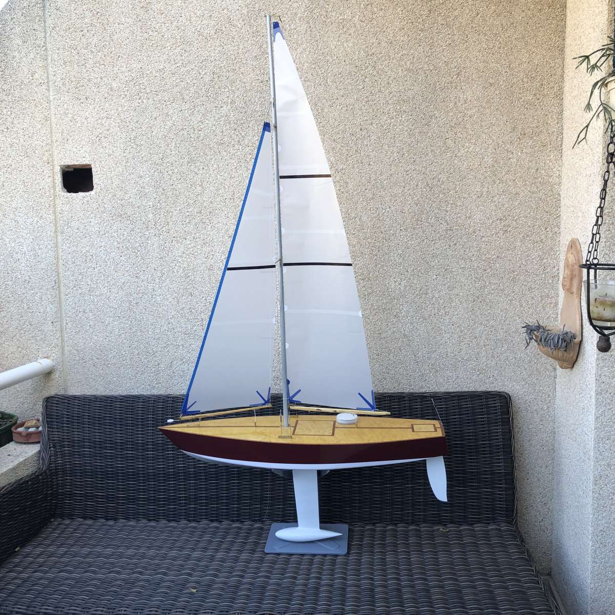
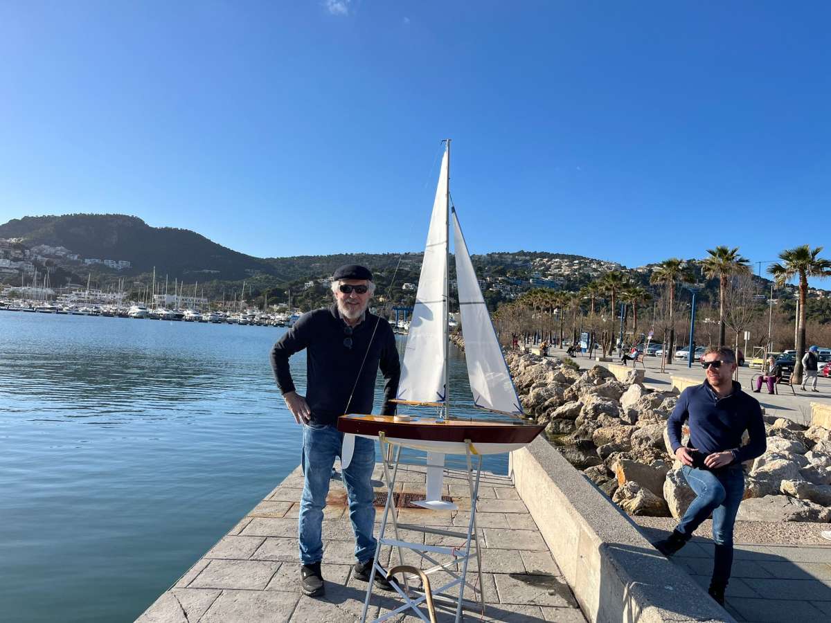
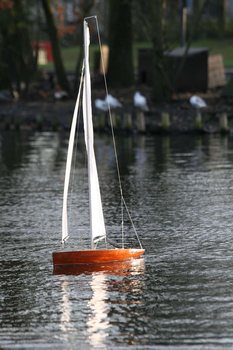
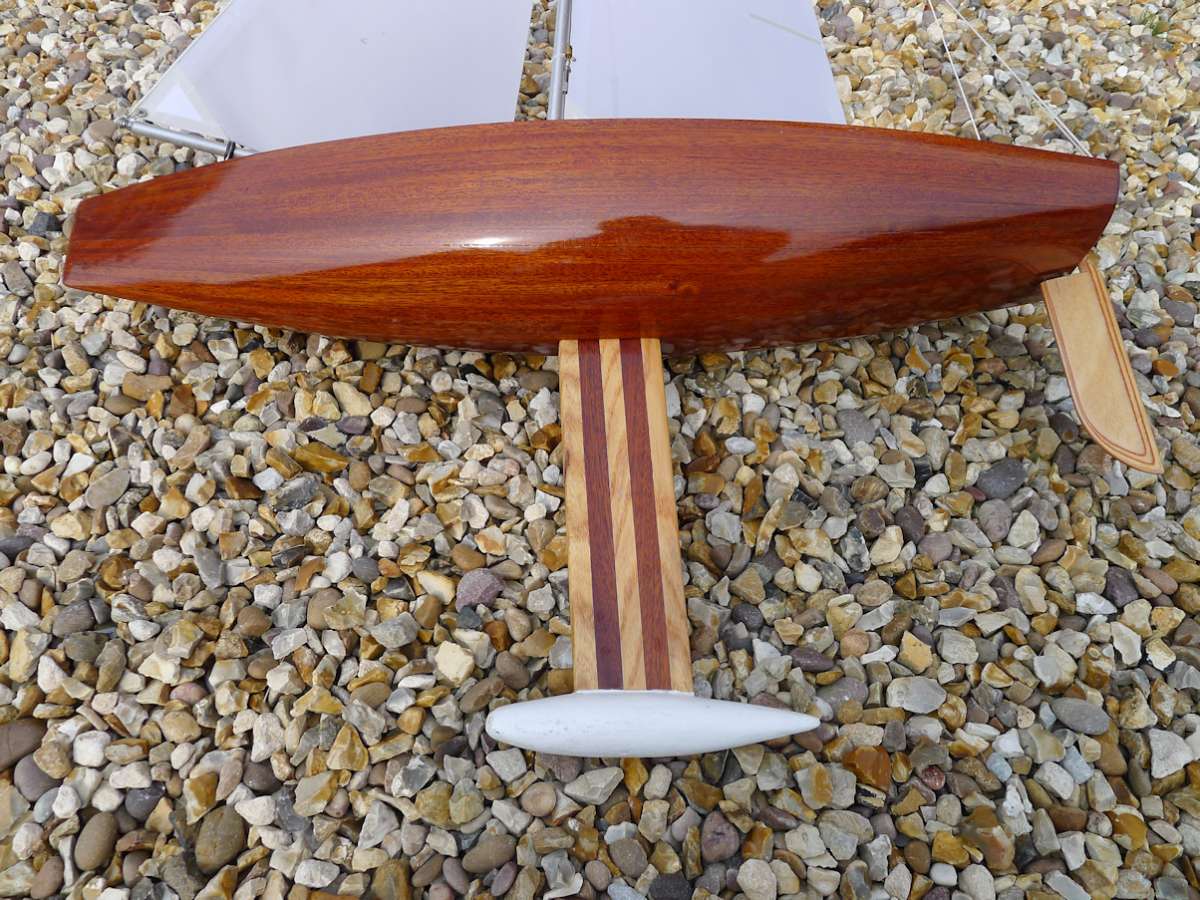
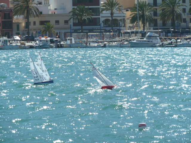
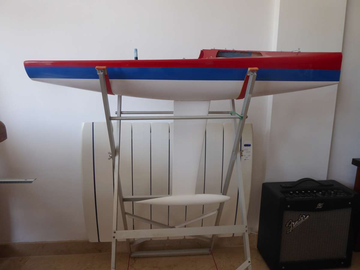
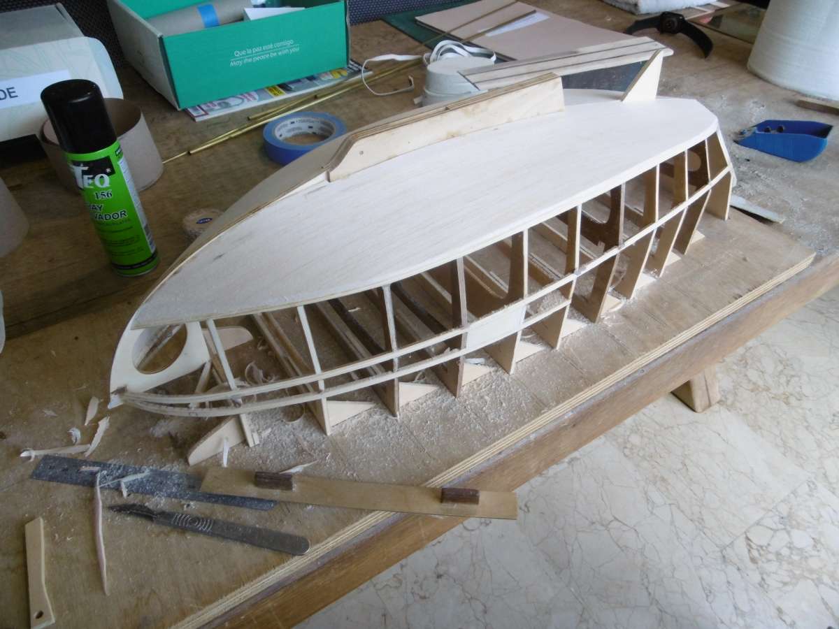
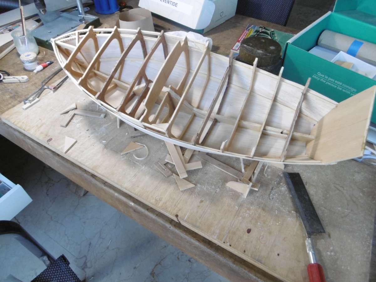
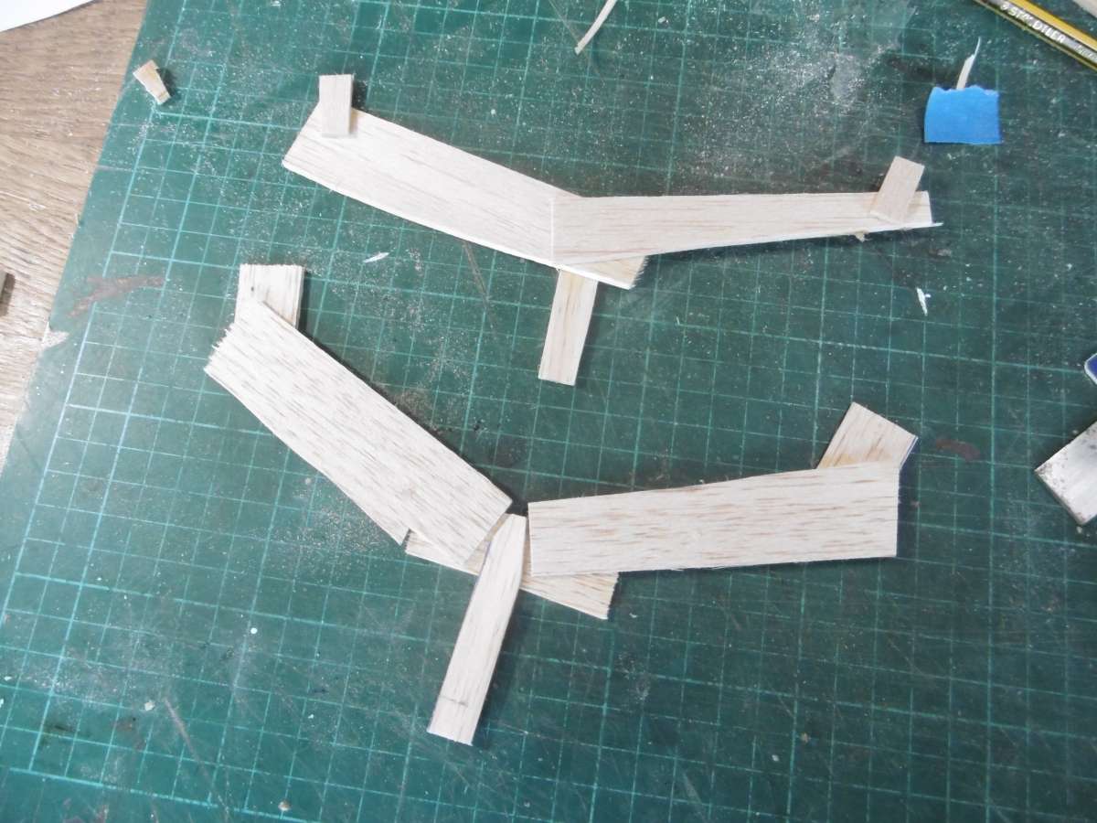
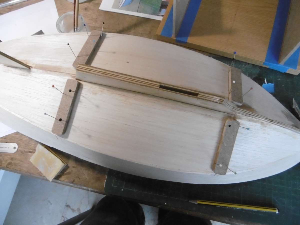
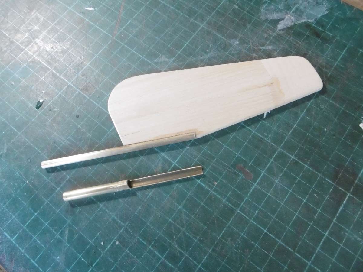
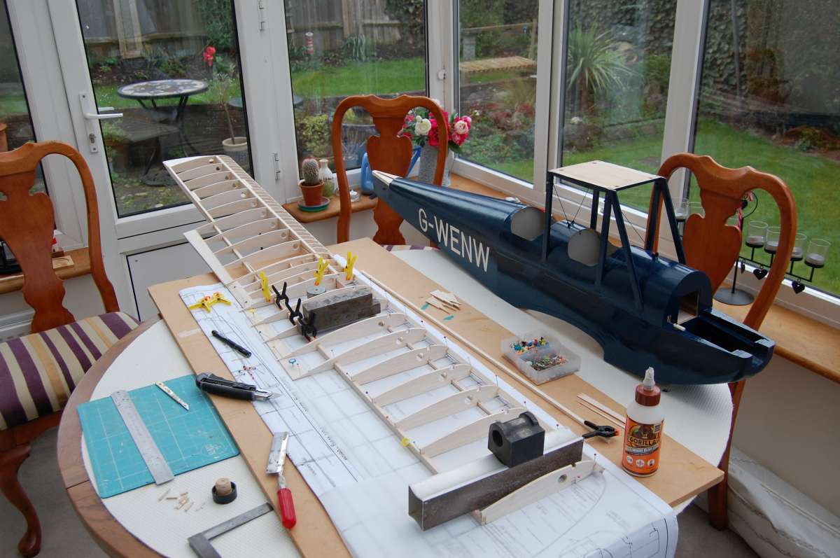
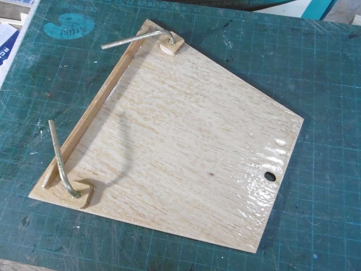
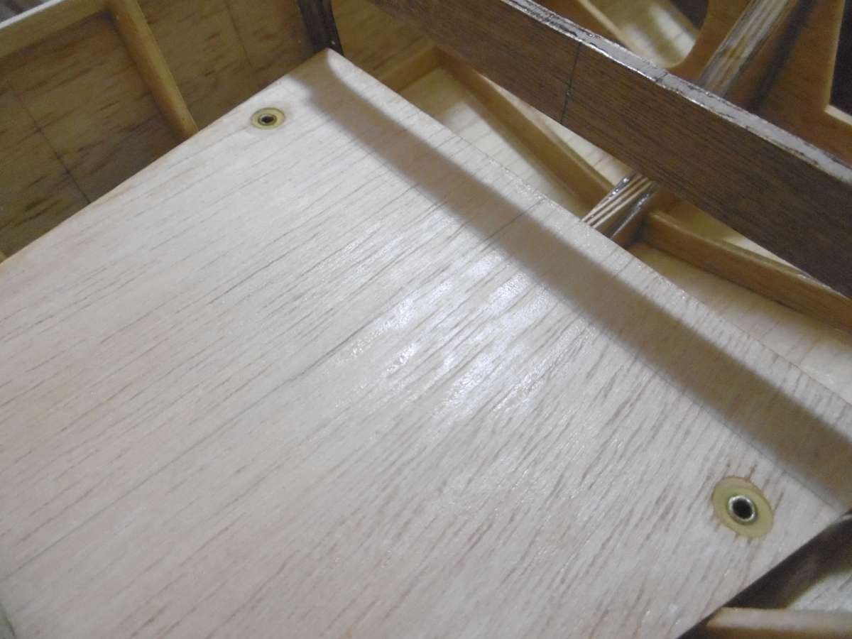
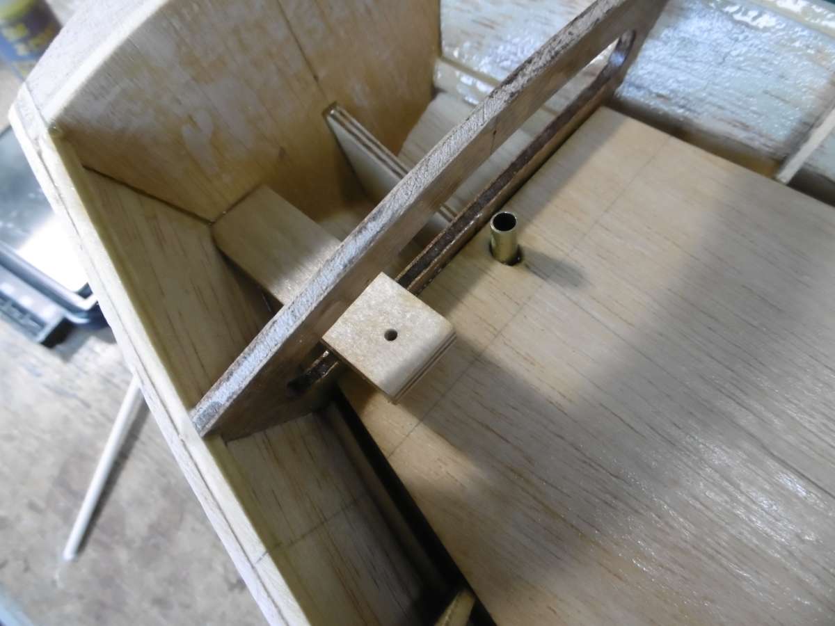
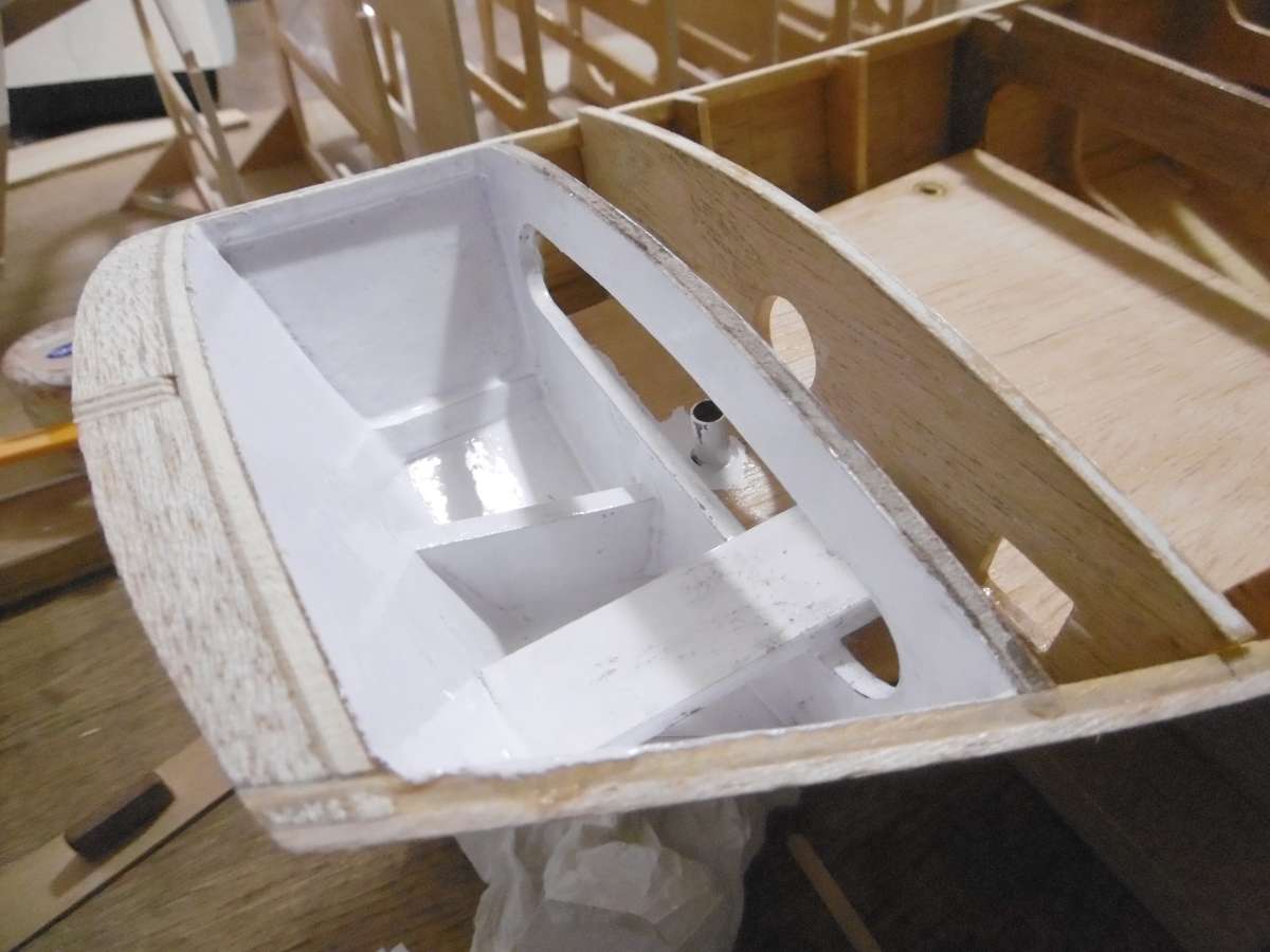
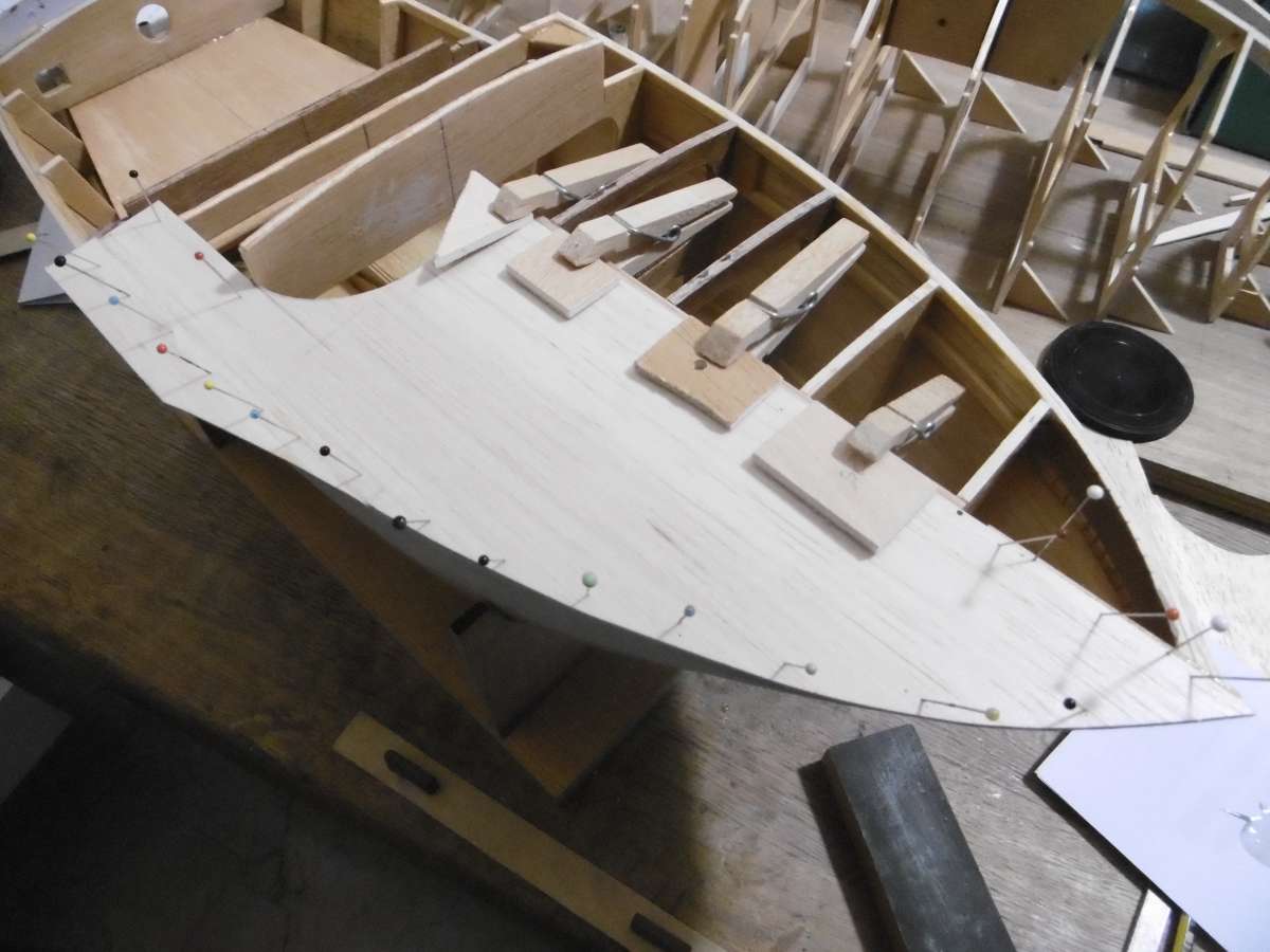
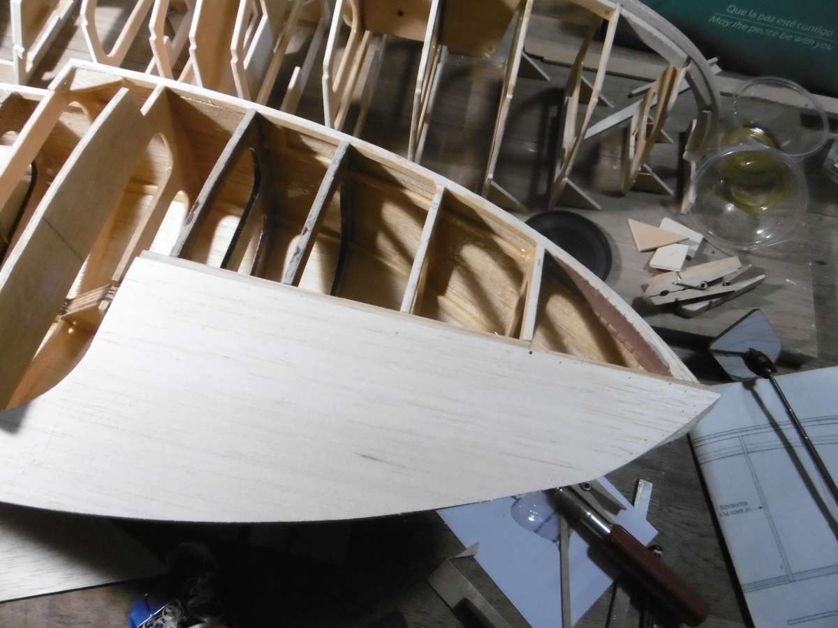
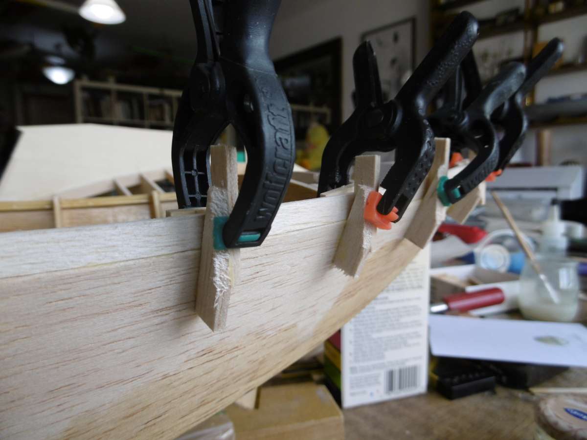
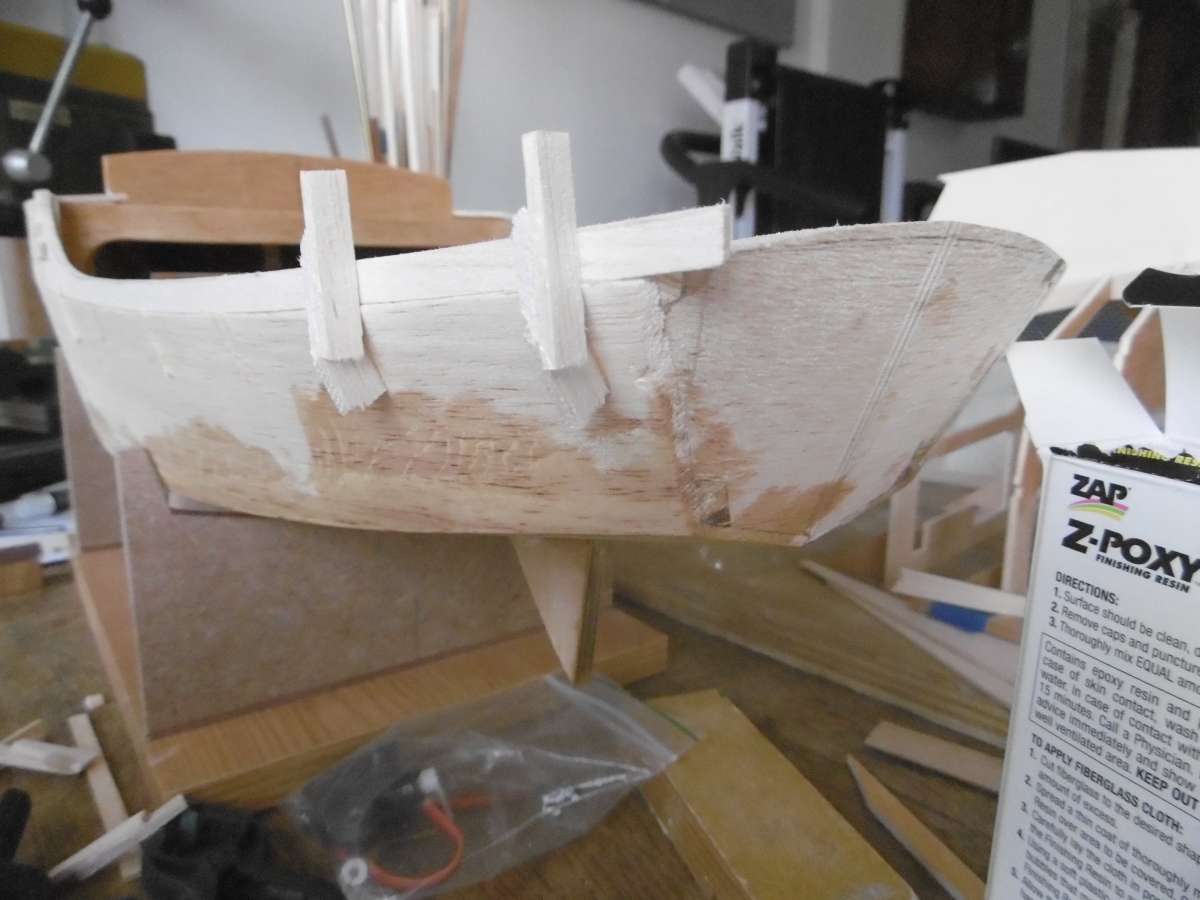
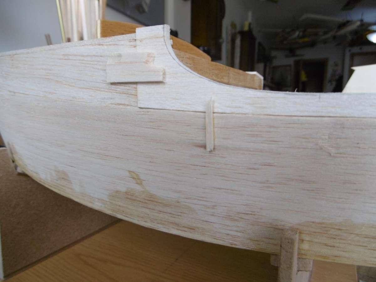
Wild Duck meets Eventide
1
2
3
4
Started by:
Tim Rowe
in: Scratch build
- 7
-
1 month, 1 week ago
Tim Rowe
-
Fairey Faun
1
2
3
4
Started by:
Chris Fellows
in: Build Blogs
- 8
-
1 month, 2 weeks ago
Tim Rowe
-
Thames Sailing Barge Stuff
1
2
…
31
32
Started by:
Ray Wood 3
in: Sailing Models
- 5
-
2 months ago
Richard Simpson
-
folding masts
Started by:
Alasdair Allan
in: All things floating
- 7
-
2 months ago
Colin Bishop
-
Fairey Fisherman 27 Motor Sailer
1
2
…
7
8
Started by:
Chris Fellows
in: Build Blogs
- 9
-
2 months, 2 weeks ago
Chris Fellows
-
MV Oldenburg 1/48th scale
1
2
…
4
5
Started by:
Ray Wood 3
in: Scratch build
- 5
-
2 months, 3 weeks ago
Ray Wood 3
-
Billing Boats Smit Nederland
1
2
…
8
9
Started by:
gecon in: Building Kits
- 13
-
2 months, 3 weeks ago
bku
-
Unable to obtain reverse on Mtroniks 15
Started by:
Campbell Sims 1 in: R/C & Accessories
- 5
-
2 months, 3 weeks ago
-
Sea Rover Restoration
Started by:
harry smith 1 in: Collectors’ corner
- 6
-
3 months, 1 week ago
-
Sea Queen By Aerokits 2025
Started by:
- 3
-
3 months, 1 week ago
-
Lost article

