
Spider J

Spider J

Home Forums Scratch build Spider J

  • This topic is empty.
Viewing 25 posts - 126 through 150 (of 201 total)
  • Author
    Posts
  • #66163
    Dave Milbourn
    Participant
      @davemilbourn48782

      Can't stay mad at you forever, m'duck. Your workmanship is always impressive and sometimes it's sheer poetry.

      Dave M

      #66164
      Colin Bishop
      Moderator
        @colinbishop34627

        Very nice work Gareth, and excellent photos too.

        Colin

        #66165
        Gareth Jones
        Participant
          @garethjones79649

          Dave,

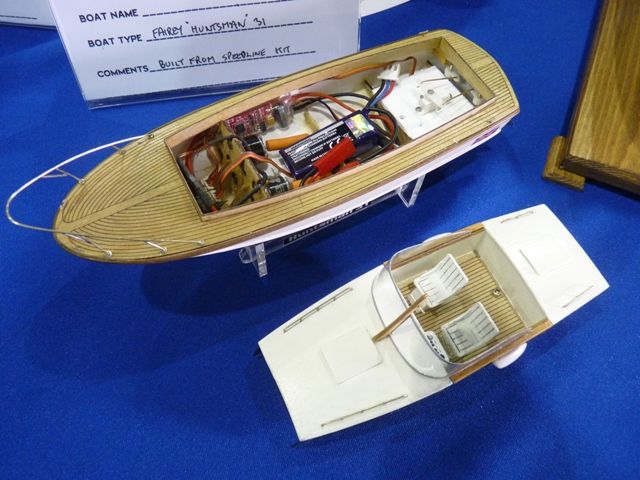
          I have been wondering if you would ever forgive me. I have been saving this picture, just for you in case you did. The model is 8 inches long and was built by Dick Milner of Rawdon MBC, photographed at the CADMA show a few weeks ago.

          huntsman 31.jpg

          Gareth

          #66166
          Dave Milbourn
          Participant
            @davemilbourn48782

            Gareth

            Thanks. I think it probably looks better with the lid on!

            Dave M

            #66167
            Steve Walker 1
            Participant
              @stevewalker1

              This build is scaring the living day lights out of me. Like so many build threads on the forum it has convinced me that I will only ever be a builder of toy boats but it doesn't diminish my admiration of the 6 or 8 of you who have left me open-mouthed at the quality of your work. And it won't stop me puddling away……

              Regards Steve.

              #66190
              Gareth Jones
              Participant
                @garethjones79649

                Steve,

                Please don't feel scared by my blog, I just post it to pass on ideas and encourage other builders. The most important thing about the hobby is that you enjoy it. If you are happy with your own models that's fine, whether they are super detailed scale models or a quick build that is thrown together in a week, it does not matter. I know several modelers whose boats look awful to me, but they sail well and the builder is happy with them so why should I criticise them.

                I don't have any exotic machine tools or exceptional skills, perhaps just the persistence to say a bit is not as good as it could be and throw it away and start again. I often make some of the individual parts three or four times over before I decide its good enough. I usually find the final part is much better than the first, and often made much more quickly. If you want to build a really good scale model you just have to take your time and have a good eye for reproducing the detail that will be on the full sized ship.

                Gareth

                #66215
                Banjoman
                Participant
                  @banjoman

                  Gareth,

                  That windlass is truly a thing of beauty, and your work to be much admired! Absolutely lovely to look at, even unpainted, and with paint on will be even more impressive, I'm sure!

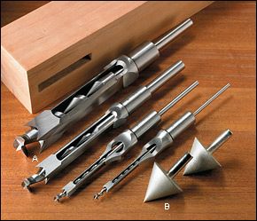
                  A wee question, though: you mention using "a square drill" to produce the cross holes. Please forgive me for most likely being dense beyond hope of redemption, but what is "a square drill" when it's at home? It sounds as though it would be a tool to drill a square section, but for the life of me I cannot figure out how it could be possible for rotary motion to produce a square result … ?!?

                  /Mattias

                  #66217
                  Dave Milbourn
                  Participant
                    @davemilbourn48782

                    A wee question, though: you mention using "a square drill" to produce the cross holes. Please forgive me for most likely being dense beyond hope of redemption, but what is "a square drill" when it's at home?

                    /Mattias

                    Mattias

                    Here's some – no doubt others are available…

                    mortice chisel.jpg

                    Edited By Dave Milbourn on 27/06/2016 09:45:44

                    #66218
                    Banjoman
                    Participant
                      @banjoman

                      Blimey! That's not half clever, that isn't! Well, we live and learn — and add even more drool-worthy tools to our wish lists! A-shopping we will go, a-shopping we will go …

                      Warmest thanks, Dave, and please consider me rather more enlightend and (at least a tad) less dense than earlier this morning.

                      /Mattias

                      Edited By Banjoman on 27/06/2016 10:06:48

                      Edited By Banjoman on 27/06/2016 10:07:15

                      Edited By Banjoman on 27/06/2016 10:07:25

                      #66219
                      Dave Milbourn
                      Participant
                        @davemilbourn48782

                        Mattias

                        Look for "mortice drills" and you will find hundreds of different types, sizes and suppliers…….o – and prices!

                        Dave M

                        #66221
                        Banjoman
                        Participant
                          @banjoman

                          Thanks again, Dave! And no, I did not expect goodies like that to be handed out for free by the Mortice Drill Fairy …

                          Hereby endeth my hi-jack of Gareth's thread.

                          /Mattias

                          Edited By Banjoman on 27/06/2016 11:41:39

                          #66242
                          Gareth Jones
                          Participant
                            @garethjones79649

                            Well spotted Mattias the reference to square drills was just a test to see who was paying attention to what I write.The holes were drilled with a conventional drill and shaped with a square file afterwards. Can’t write anymore now, as we are on holiday on the Isle of Man and have no internet access on my laptop. Gareth

                            Edited By Gareth Jones on 28/06/2016 19:13:32

                            #66526
                            Gareth Jones
                            Participant
                              @garethjones79649

                              Well, I am back from the Isle on Man now, but had a week at home with no landline or internet access, apart from on my mobile phone. However after the helpful BT engineer eventually found the fault in a mysterious green box hidden in the hedge in our village things are back to normal. (It was some device, now redundant that protects the telephone system from lightning strikes. Everybody else had been disconnected from it except us)

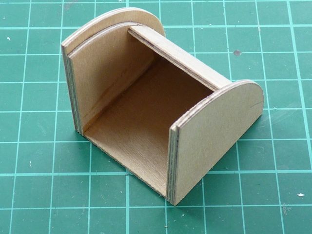
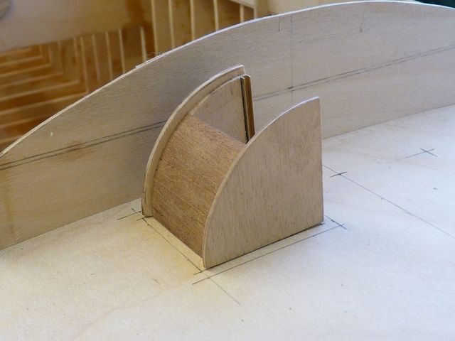
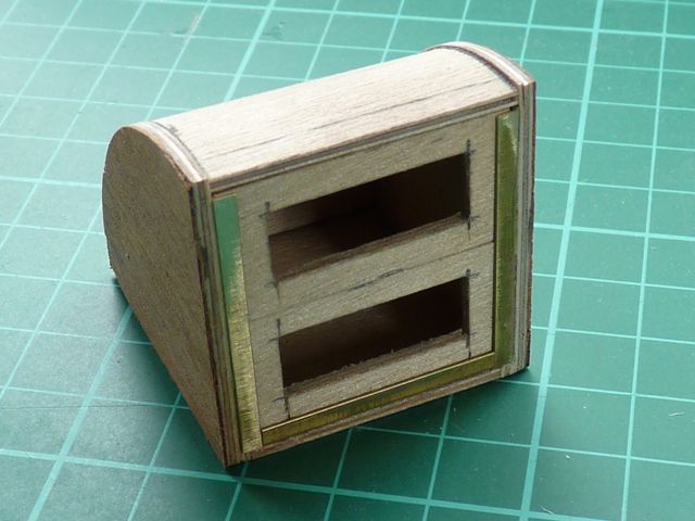
                              The next item to be made for Spider J was the companionway which sits on the aft deck. According to the drawing it was made in teak but since I did not have any suitable teak planking I have used mahogany instead. However its started life as a 1.5 mm ply box structure to give it the required shape.

                              spider 117.jpg

                              The planking was added along the fixed part of the roof and brass channel to make the slides where the two removable entry panels fit.

                              spider 118.jpg

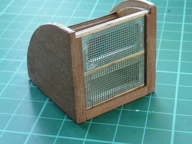
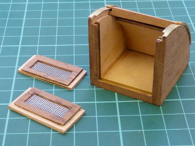
                              The two front panels were cut from ply with a rectangular hole where there will be a grille made from photoetched brass. I think the real thing has a wooden grating but its too difficult to see this area on my photos of keels and sloops. The sliding roof was made from a piece of 1.5 mm ply boiled for a few minutes in a pan and then taped over a piece of tube overnight to take up the required curve. The mahogany planking has been added to the sides now.

                              spider 119.jpg

                              Now the grilles have been added and the framing on the front.

                              spider 120.jpg

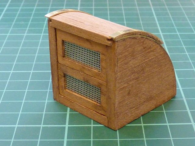
                              Here is the final assembly with the brass running strips and mahogany planks added to the roof

                              spider 121.jpg

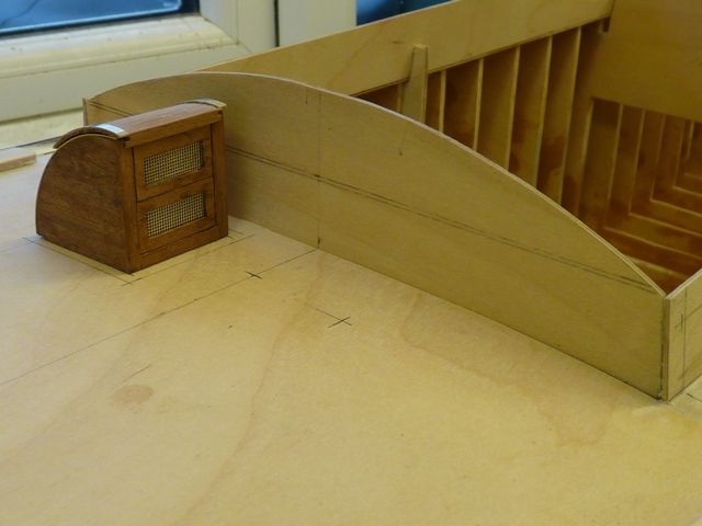
                              Since the roof slides open and the two front panels can be removed I guess it means I will have to cut a hole in the floor and rear deck to show the ladder leading down into the cabin. It also needs a hand rail on the inside of the companionway and a hasp on the sliding roof so the cabin could be secured when the boat was left unmanned.

                              spider 122.jpg

                              Here's a final picture of it in place. There are three short pieces of angle to be added, which locate it on the deck.

                              spider 123.jpg

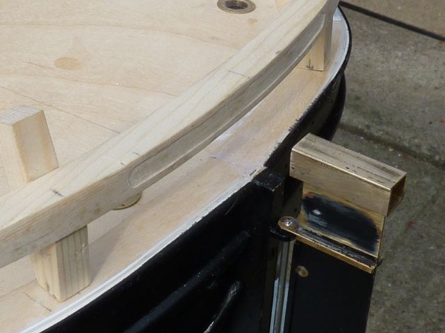
                              The next item to be made is the rear rail and bollards. The rail is approx 10 mm square pine which will need bending to a reasonably gentle curve. However it will need boiling in a pan I think if I am to avoid cracking it.

                              Gareth

                              #66577
                              Banjoman
                              Participant
                                @banjoman

                                Gareth,

                                That is a very, very pretty companionway shelter indeed, and I rather see what you mean when contemplating cutting through the deck to add the actual companionway!

                                An alternative that you might consider if you don't want the bother of cutting through the deck, and making everything watertight below, is to just simulate the opening by some black paint and dummy handrails, like I did on Eilean Mòr (see **LINK**, about halfway down the page). Of course, the real thing would look much better, and be a further lovely detail, but the dummy solution is sarprisingly effective, I'd say: unless one comes up very close, it looks quite realistic.

                                /Mattias

                                #66581
                                Bob Abell 2
                                Participant
                                  @bobabell2
                                  I'm sure Gareth will cut through and even fit the steps

                                  He loves fine detail

                                  Bob

                                  #66702
                                  Gareth Jones
                                  Participant
                                    @garethjones79649

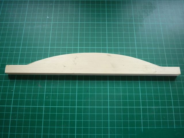
                                    The next step has been the rails around the stern. This has been a bit problematic, I did not think trying to bend a bit of 10 mm square pine would be so difficult. The problems are that it needs to bend in two dimensions, to follow the curve of the stern and also the camber of the deck. I have got through a lot of B and Q stripwood trying to do this. One complication is that the shape to follow the stern needs to be a U but the first few attempts came out as a V. The other complication is that I needed to route a recess in the aft side of the beam as the name pf the vessel is usually painted in that area. Anyway, here is the way I eventually made the bits.

                                    Firstly I cut the shape of the aft side of the beam from a piece of pine 10.5 mm thick and about 34 mm wide.

                                    spider 124.jpg

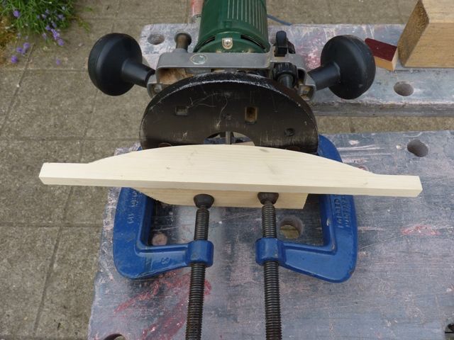
                                    Then I routed the recess in the rear face. Initially I tried to do this with a Dremel but eventually found my full sized Bosch router was more suitable.

                                    spider 125.jpg

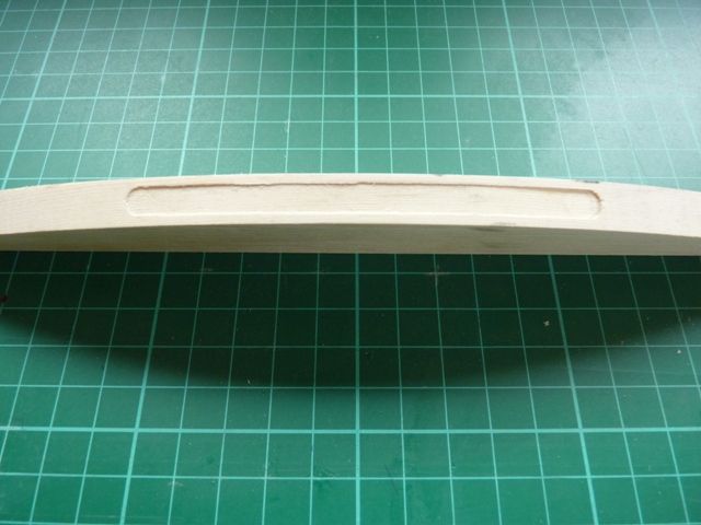
                                    Heres the recess in the rear face.

                                    spider 126.jpg

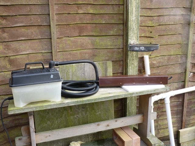
                                    Then I steamed it for about 30 minutes in my home made steamer, the section of brown gutter downpipe connected to a wallpaper stripper.

                                    spider 127.jpg

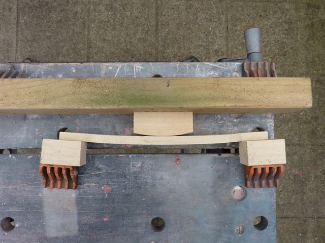
                                    Then I bent the piece of wood to follow the camber of the deck, leaving it overnight in the workmate to cool.

                                    spider 128.jpg

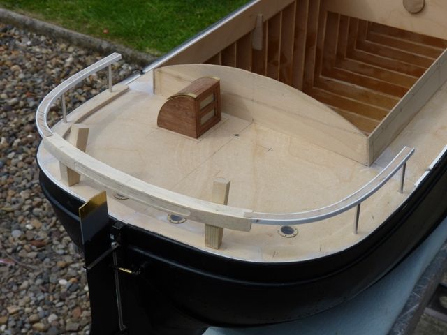
                                    The surplus material was then cut away leaving a square section beam of the right length.  Here is the installed beam with the two side rails also fitted. The side rails are made from 1.5 mm ply with 4 mm x 1 mm styrene strip to form the edges.

                                    spider 129.jpg

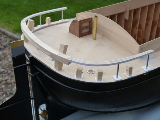
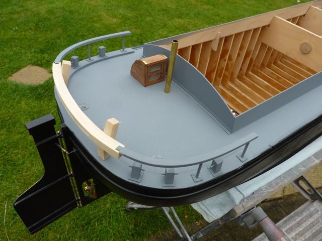
                                    The deck lights have been fitted, made from flanged brass portholes with the raised rim around the 'glass' sanded off. I have also added the timber heads, made from some pine stripwood, sanded to the right size with 1.5 mm brass rod to pin them to the deck and provide the mooring rope bars.

                                    spider 130.jpg

                                    The next challenge is going to be the tiller – more steaming required I think.

                                    Gareth


                                    Edited By Gareth Jones on 22/07/2016 21:07:32

                                    #66923
                                    Gareth Jones
                                    Participant
                                      @garethjones79649

                                      There has been a bit more progress on Spider J over the last few weeks. There have been Folksail events in Hull and Goole last month, attended by a number of sloops and keels. This gave some good opportunities for taking photographs and measurements, asking questions and trying to work out the rigging and which rope goes where.

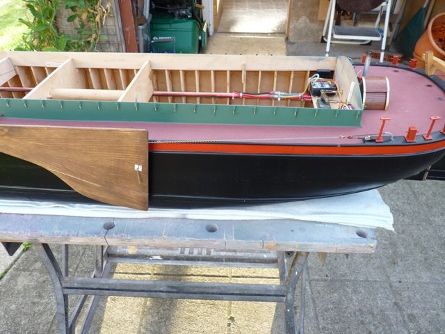
                                      Spider J has now has the deck and coamings undercoated.

                                      spider 131.jpg

                                      spider 132.jpg

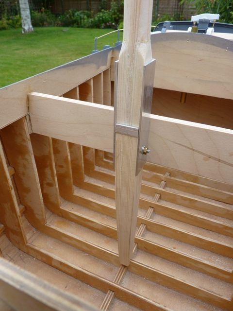
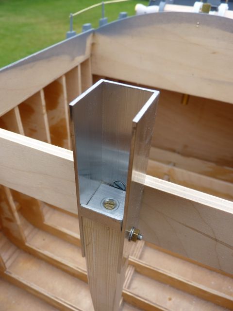
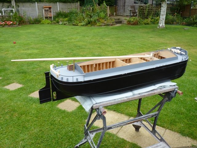
                                      She has also acquired a mast and lutchet. The lutchet is designed to mimic the real thing in principle but is slightly different in practice. The lutchet itself is made from a short length of 20 mm square aluminium U channel. A tapered wooden strut extends down to the keel to take the vertical loads from the mast and rigging. In the real vessel this would be a tapered steel construction. The tapered strut is pinned to the keel and bolted into the lutchet.

                                      spider 133.jpg

                                      An aluminium plate with a short flange on its back edge provides the resting point for the mast.

                                      spider 134.jpg

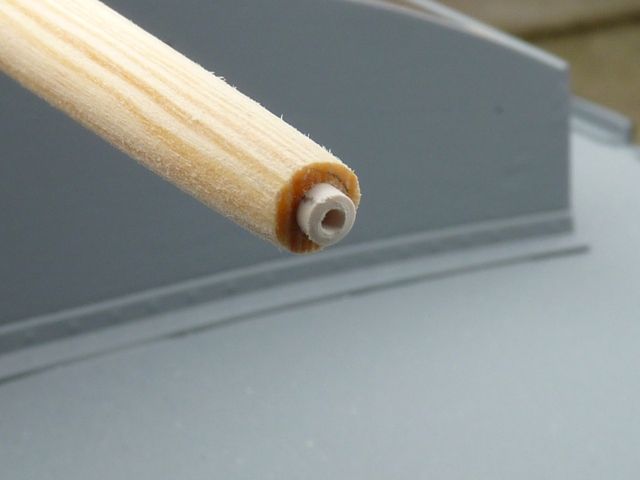
                                      The mast was made from a piece of 18 mm pine dowel, planed and sanded down to the right degree of taper. The bottom starts at 16 mm and tapers to 14 mm where the cross trees will be attached. The top section above that tapers down to 6 mm diameter. I have inserted a short length of 3 mm plastic tube into the top of the mast to fit the wind vane and burgeee.

                                      spider 138.jpg

                                      The bottom of the mast has a short square section that locates in the lutchet. I made this by drilling out a piece of 32 mm square pine with a 16 mm drill and then planing and sanding it down to 17 mm square outside dimensions. This took several goes before I managed to make it work. The square section blends into the 16 mm round diameter just above the lutchet. The bottom of the square section is rounded off so that the mast can be rotated backwards to lower it.

                                      spider 136.jpg

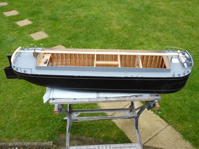
                                      Hopefully the model will be able to be transported with the mast and sails folded down within the overall length of the hull which is 48 inches, since the mast is not actually pinned into the lutchet.

                                      spider 137.jpg

                                      #66924
                                      Gareth Jones
                                      Participant
                                        @garethjones79649

                                        I have made a start on the hatch cleats and made and trial fitted the first few prototypes.

                                        spider 139.jpg

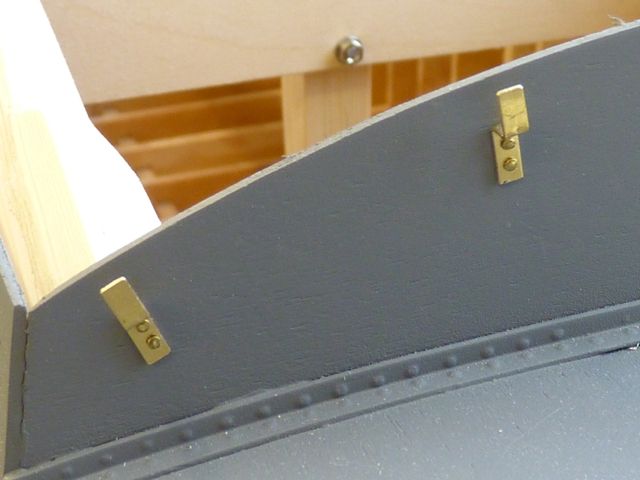
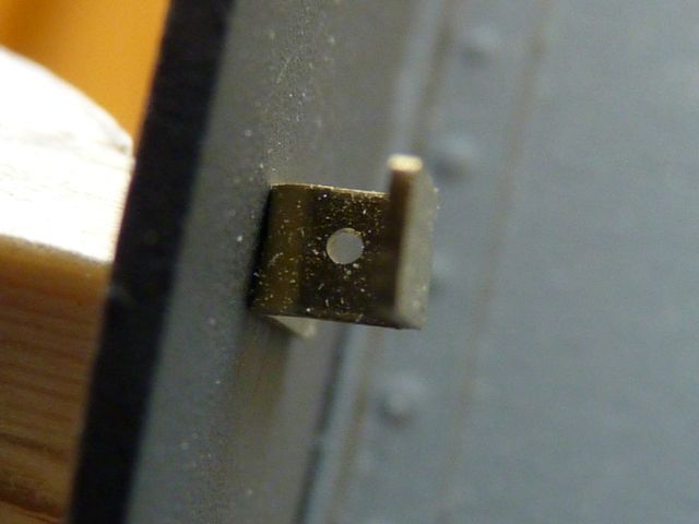
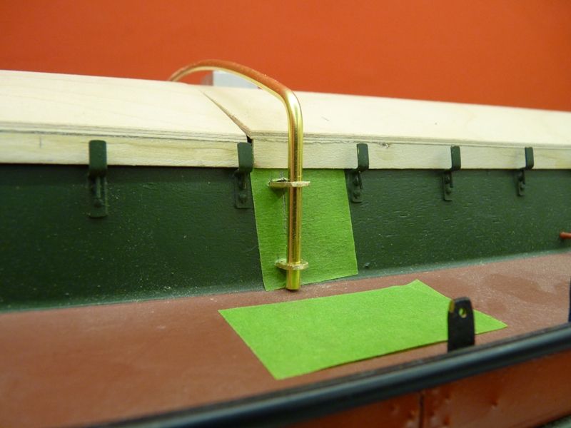
                                        Each cleat has a vertical pin through the center section so it doubles as a cleat to take the wedges that hold the hatch bars and also the ropes that are used to provide additional lashing over the hatch tarpaulins.

                                        spider 140.jpg

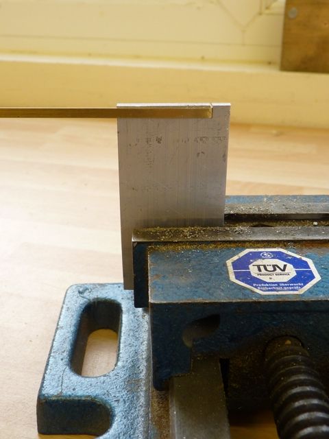
                                        I have 68 cleats to make in total so I have made a simple jig to allow them all to be bent to the same size. Its just a small piece of steel strip with a saw cut just wide enough to take the 3 mm x 0.5 mm brass strip used to make the cleats.

                                        spider 141.jpg

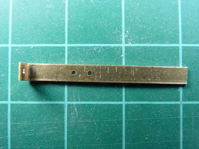
                                        I have also made a jig from a bit of brass strip for drilling the holes for the rivets (actually 0.7 mm brass pins) that secure the cleat to the coaming. It is also used to drill the center hole in the cleat.

                                        spider 142.jpg

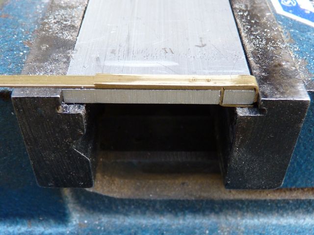
                                        Here's the jig in use to drill the two rivet holes. In this case the cleat is located in a piece of aluminum strip while being drilled. After drilling the holes it's cut off to approximately the right length and then trimmed to size on the disc sander.

                                        spider 143.jpg

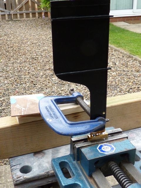
                                        The other bit of progress has been the box section on top of the rudder that takes the tiller. This should really be tapered but I have made it parallel from two pieces of brass angle soldered together. These were then soldered on top of the rudder, with a G clamp acting as a support and heat sink to stop all the existing soldered joints from melting and falling apart.

                                        spider 144.jpg

                                        Here's the final assembly after all the surplus solder has been filed off and cleaned up.

                                        spider 145.jpg

                                        I have not yet worked out how I am going to make the tiller. I did take the dog for a walk down by the canal last week and stole a couple of oak twigs to see if I can bend them to shape but did not get round to trying that evening so they are probably too dry now.

                                        One of the areas that I measured up on the sloop Amy Howson at Goole last weekend were the lee boards so I think I might start making them next.

                                        Gareth


                                        Edited By Gareth Jones on 03/08/2016 16:09:39

                                        #66990
                                        Gareth Jones
                                        Participant
                                          @garethjones79649

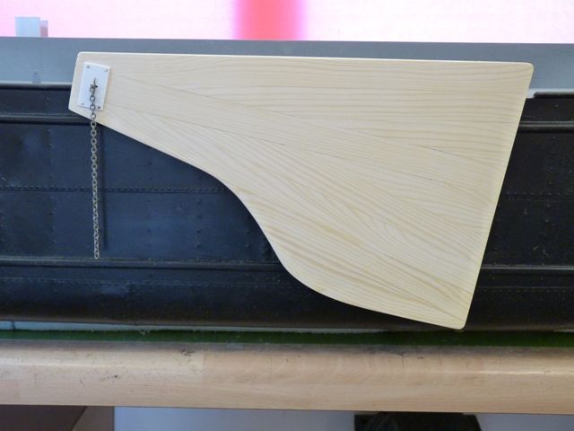
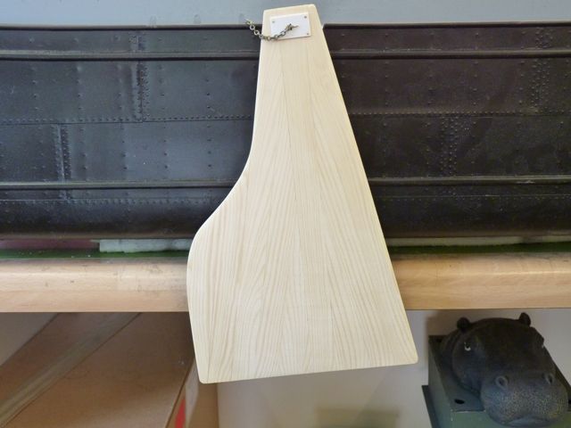
                                          The first of the leeboards has now been assembled, although its still lacking a lot of detail and its operating chain. Fortunately I had a scale drawing of a leeboard, plus a lot of constructional information to work from. The Humber Keel and Sloop organisation used to publish a regular magazine known as The Slabline and these are all available to download from their website. ( **LINK**) In some of the early editions was a series of articles entitled Talking Technically which provide a lot of detailed construction information which is proving really useful when building the model.

                                          The leeboard has been made from 18 m x 4 mm pine strip wood (from B and Q) glued edge to edge with medium superglue. There are two battens on the back which are intended to give the board a degree of camber, although that is proving difficult at the moment as the battens have become cambered rather than the boards. However a soak in water and clamping up overnight should fix that. The board tapers from around 4 mm thick at the top to 3 mm at the foot which has been achieved by sanding the completed assembly.

                                          spider 146.jpg

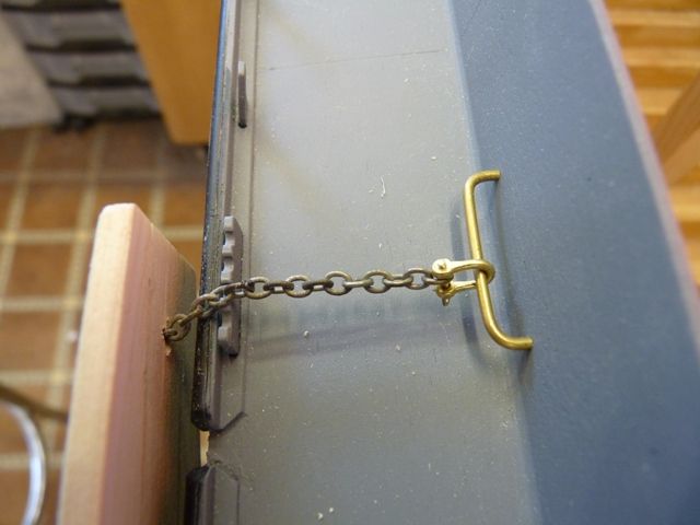
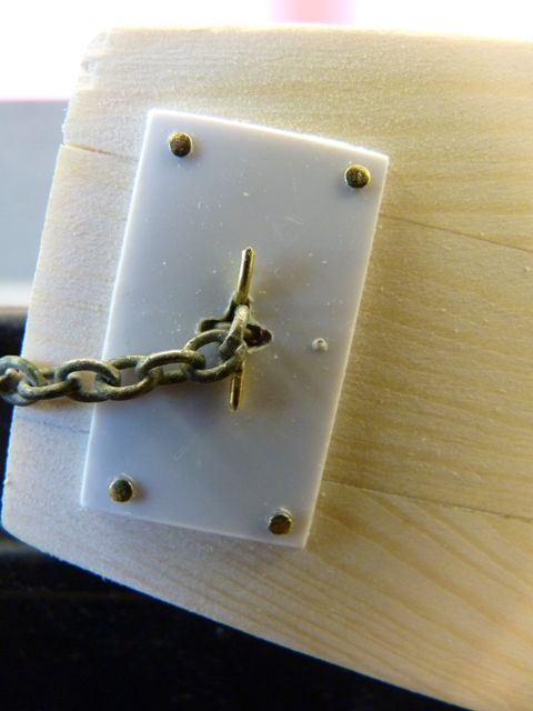
                                          The front attachment point is unusual in that the chain passes through a cross shaped hole in the board, reinforced by a steel plate on the real ones but styrene sheet on the model. A U shaped strap passes through one of the chain links to secure it in place but I have used a suitably shaped bit of brass wire. Here is the attachment chain from above, which is secured to the traveler on the coaming and located in a grooved plate on the edge of the deck.

                                          spider 147.jpg

                                          Here is a close up of the chain attachment on the outside of the board. I have not cut the surplus chain off yet as I might need to adjust the length before I have finished.

                                          spider 148.jpg

                                          Finally here is a photo showing the leeboard in the lowered position.

                                          spider 149.jpg

                                          I don't expect the leeboards to be particularly effective when sailing the model as they are unlikely to scale very well hydro-dynamically. However they are an integral part of a sloop or keel and making them a working assembly adds to the interest of the model and its construction.

                                          Each leeboard will be operated by a 6 turn captive drum sailwinch mounted in the aft of the hold. The control cable will exit through the deck and hopefully be disguised as part of the normal hand winch used to raise and lower the boards. There is a double purchase cable system with a pulley block attached to a length of chain which is connected to the centre of the leeboard foot. Since the leeboards will tend to float up when lowered I will probably have to add some lead strips to the bottom of them. There are a whole series of reinforcing bars which run round and across each board that I have yet to add. I will need to stain the bare wood first.

                                          My next task is to continue making and fitting all the hatch cleats and then I plan to finish painting the hull, deck and coamings. This is not intended to be a model of any particular keel so the paint scheme is whatever takes my fancy. At the moment I favour a red stripe along the top edge of the hull with red hawse plates at the bow, dark reddish brown deck and green coamings. The timber head mooring points will also all be red, at least that's the plan for the present.

                                          Gareth

                                          #67544
                                          Gareth Jones
                                          Participant
                                            @garethjones79649

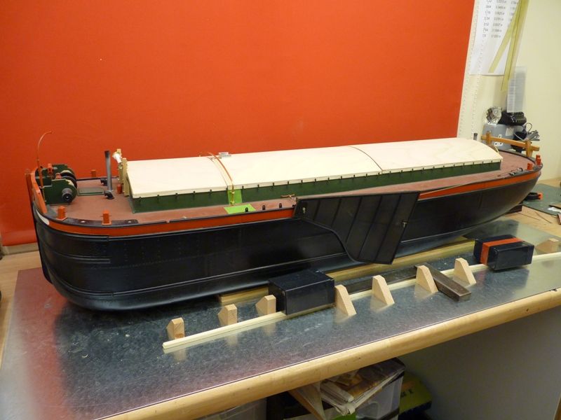
                                            Its a while since I posted an update on Spider J but I have made some progress over the last month. The deck and coamings have been painted, although I am not struck on the matt green of the coamings and I am going to respray them in a silk finish.

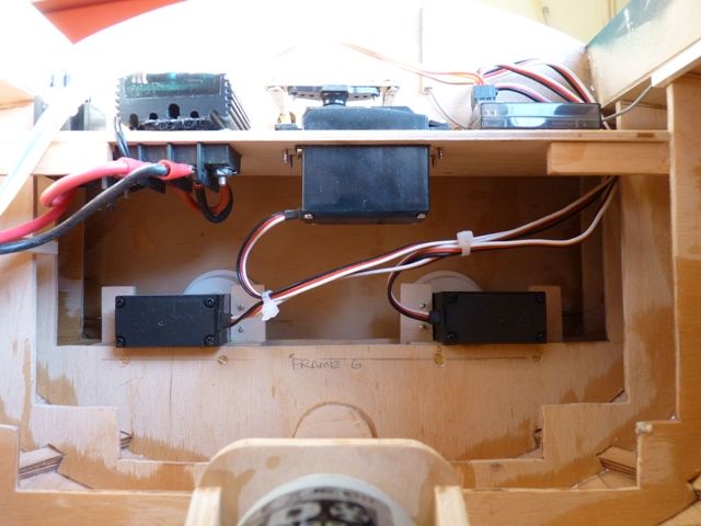
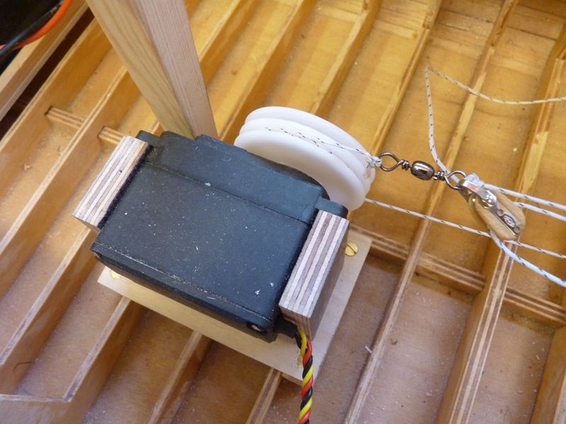
                                            The lee board operating servos have been fitted and one of the boards is now fully functional. There are two 6 turn sailwinch servos fitted at the very back of the hold, one for each lee board. A cord runs from the captive drum of the servo through a S shaped length of brass tube which guides the cord out through the deck at the point where the manually operated roller would normally be. The servos are operated from the gear and flap switches on the transmitter, just giving a fully up and down position.

                                            Here is a view of the two servos.

                                            spider 150.jpg

                                            And here is the top of the guide tube

                                            spider 151.jpg

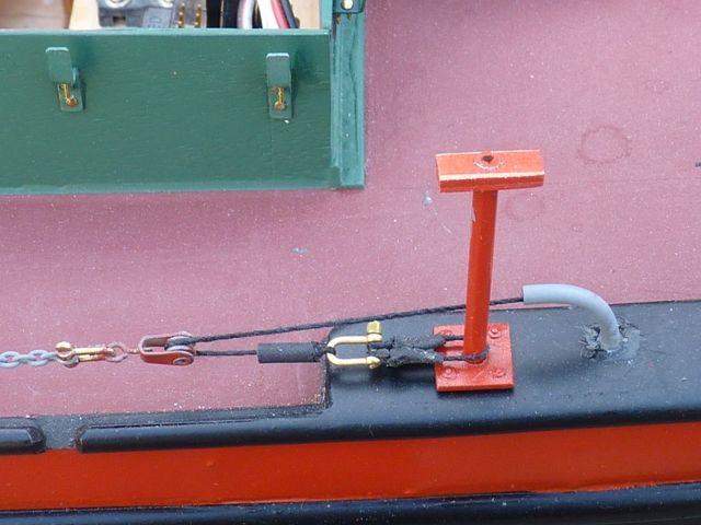
                                            The end of the cord is anchored to the rail post in the same way as on the full sized sloop. A chain passes over a pulley mounted just above the aft end of the lee board.

                                            spider 152.jpg One area that still needs a bit of development is this forward pulley as occasionally the chain catches on the side plate and causes a jerk in the system.

                                            spider 154.jpg

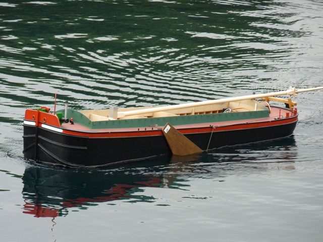
                                            However, other than that it seems to work reliably and does not snag. By sheer chance the 6 turn travel of the Component Shop sail winch is exactly right for the system, with a bit of judicial positioning of the attachment of the chain to the lee board. They also operates nice and slowly, looking quite realistic for this application (but slow for operating the sails on a racing yacht). Here is a picture of the model afloat with the lee board just about to complete its travel downwards.

                                            spider 153.jpg

                                            There is still some work to do on the lee boards to add the reinforcing bars. However before I do that I plan to build the right hand board and see if I can achieve a better curve in the board profile as the left hand one has turned out almost flat. If the right hand one is better I will probably scrap the one I have already made and make another.

                                            #67545
                                            Gareth Jones
                                            Participant
                                              @garethjones79649

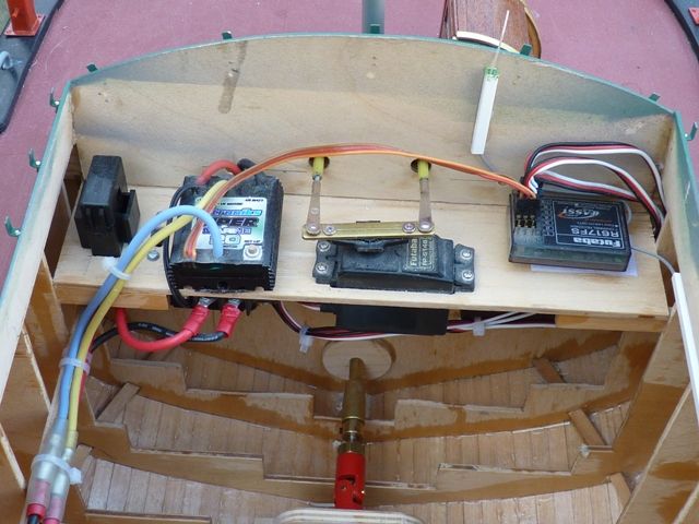
                                              The internal electrics have all been added with most components mounted on a shelf at the aft end of the hold.

                                              spider 155.jpg

                                              However all is not well as after about 15 minutes sailing last weekend the main 10 amp fuse, mounted in the left hand corner in the picture above, ruptured fortunately just as I had brought the model to the pond side. I have just blown another two fuses this morning so I have a fault to find.

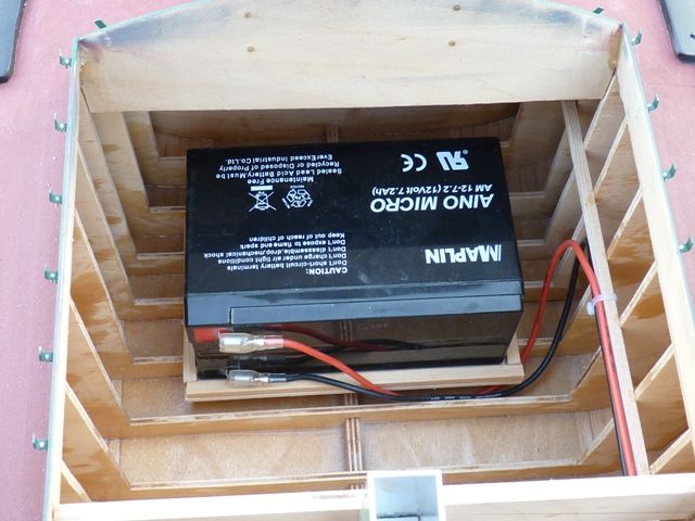
                                              The battery is mounted at the forward end of the hold on a plate fixed to the floor.

                                              spider 156.jpg

                                              The main sail winch servo and its operating loop will run down the center of the hold from just behind the mast to the aft end, with the sheets emerging just behind the aft headledge and just in front of the mast.

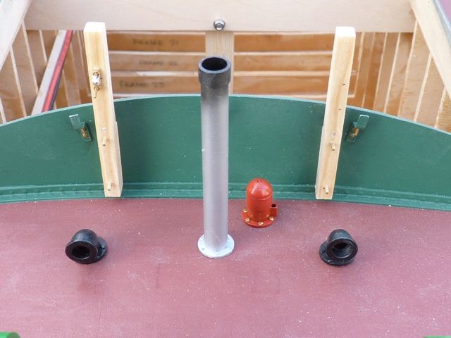
                                              The water pump and chain pipes have been made and temporarily fitted on the fore deck. The chain pipes are made from 8 mm styrene tube, cut in sections to get the 90 degree bend and then sanded smooth with a small lip around the top edge and a bigger mounting flange at the bottom. Photo-etched brass nuts complete the mounting detail. In the background you can see the prototype forward roller mounts. The deck is not really the purple colour it looks on my monitor at least, its really a rusty brown.

                                              spider 158.jpg

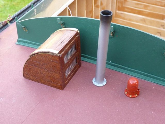
                                              On the aft deck the companionway has been varnished and the stovepipe and water pump fitted. I have still got some painting to do on the red bits of the model which I will carry out this week when my supply of Revell aqua colour fiery red satin are topped up.

                                              spider 157.jpg

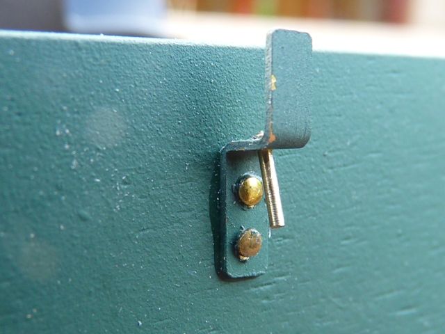
                                              All 68 hatch bar cleats and pins have been fitted and now await the final coat of dark green satin paint.

                                              spider 159.jpg

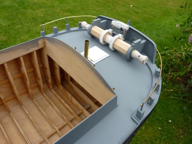
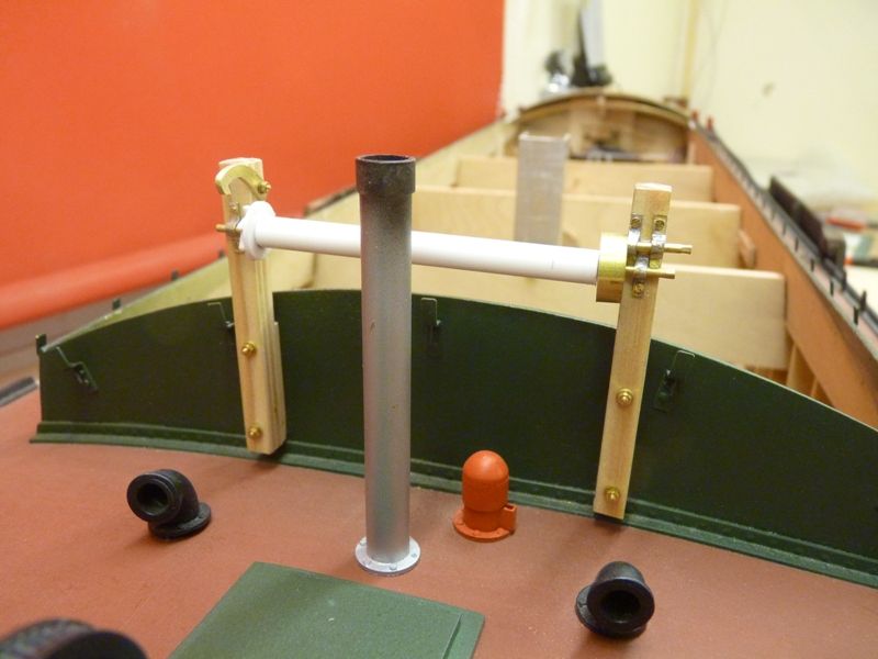
                                              The job currently in progress is making the winch/roller assembly which is attached to the front headledge and is used to raise and lower the mast, via a stayfall pulley assembly attached to the stem of the vessel.

                                              Gareth

                                              #67550
                                              Banjoman
                                              Participant
                                                @banjoman

                                                Gareth,

                                                This build continues to be tremendously impressive, and a pure joy to behold! It is a privilege to be able to follow it as it progresses!

                                                Mattias

                                                Edited By Banjoman on 06/09/2016 07:19:12

                                                #74828
                                                Gareth Jones
                                                Participant
                                                  @garethjones79649

                                                  Until the last few weeks I had not made any progress on Spider J since my last posting above. This has been due to a wide variety of reasons, on the modelling front, mainly various model racing yacht jobs. Various other activities have also sidetracked me including working, gardening, decorating, holidays (South Uist and the Isle of Man), changing sheds and socialising a Hearing Dog puppy (Rodney, a cocker spaniel who is even now sitting with his head on my knee looking for some attention). However now that the shed swap is complete and the workshop has been tidied up I have been inspired to restart work on my Humber sloop Spider J.

                                                  The front headledge winch has progressed to the point where it is recognisable. It still needs a tiny pinion and some teeth on the internal gearwheel on the right hand side in the picture. Bob Wilson's tiny dead eyes are a good inspiration to come up with something convincing to complete the assembly. I am quite pleased with the pawl/ratchet mechanism at the other end of the roller.

                                                  spider 160.jpg

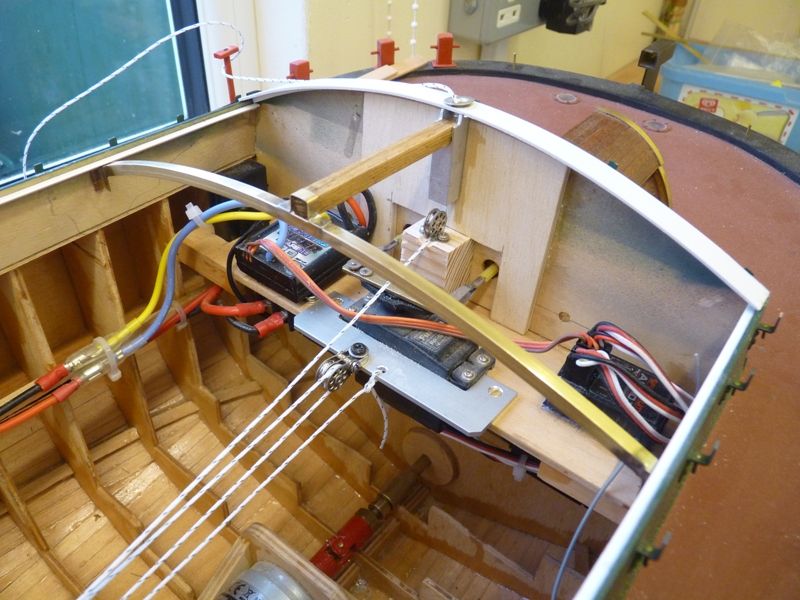
                                                  The sailwinch has been installed just aft of the mast lutchet. I have used a Hitec drum type with a loop of heavy duty braided line running back to a double pulley which is attached to the rear equipment shelf. A swivel tied into the loop provides the means of attaching the sheets which control the main and jib sails. The loop is just tensioned by pulling the lines tight before tying them. In one or two installations I have included a spring in the return side of the loop to maintain tension but in practice, they have caused more problems than they cured.

                                                  spider 161.jpg

                                                  spider 162.jpg

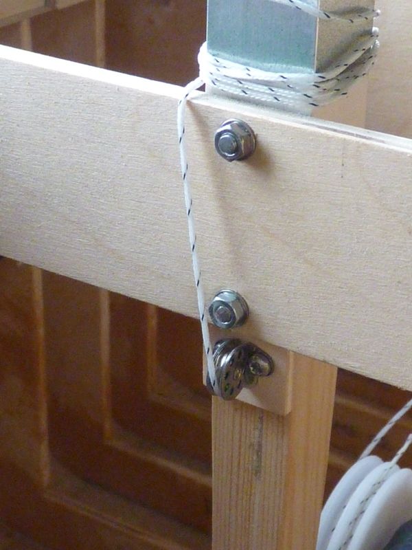
                                                  The sheet travel required on the mainsail is longer than I have available as a single run in the hold so the travel is doubled by attaching one end of the mainsail sheet to the aft ledge and then running the line around a pully (or maybe I should say a sheave) attached to the swivel on the sailwinch loop. The sheet then runs back aft and under a small pulley before exiting the hold just forward of the aft headledge via a fairlead on the top centreline. The fairlead is an adapted metal rivet from a large 'popper'

                                                  The sheet to the jib runs aft from the swivel, around the second pully (alongside the one for the servo loop), then forward through fairleads in the frames which support the lifting handle and the centre of the lutchet. It then goes around another small pulley and will exit the hatch just forward of the mast.

                                                  spider 163.jpg

                                                  Time will tell whether this is a reliable sail control system and the first few sailings will reveal whether the sheets all get tangled up when they go slack. However the whole system is reasonably accessible as all the hatch covers will be removable and improvements can be made if necessary.

                                                  More later

                                                  Gareth

                                                  Edited By Gareth Jones on 04/01/2018 09:30:49

                                                  Edited By Gareth Jones on 04/01/2018 09:34:22

                                                  #74830
                                                  Gareth Jones
                                                  Participant
                                                    @garethjones79649

                                                    The next bit or progress has been on the hatches. On the full sized vessel these are made up of a series of individual sections each with a pair of curved T section beams with cross pieces of tongue and grooved boards. Most of these span the full width of the hold but at the back and just behind the mast the covers are in two pieces with a central supporting beam. I am not planning to cover all of the hold with realistic hatches, just the aft section for display purposes. When sailing this will be replaced by a more secure covered hatch.

                                                    spider 164.jpg

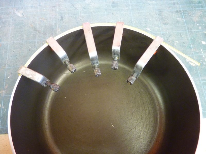
                                                    The rear curved brass cross beam and longitudinal timber support can be seen in the picture above. The T section brass hatch beams also have to be curved and this is tricky as the metal wants to twist when you try and bend it. The best method I have found is to bend them cold around a suitable former, in this case an 8 inch aluminium sauce pan as shown below. The same method was used for the brass angle section which spans the hold.

                                                    spider 165.jpg

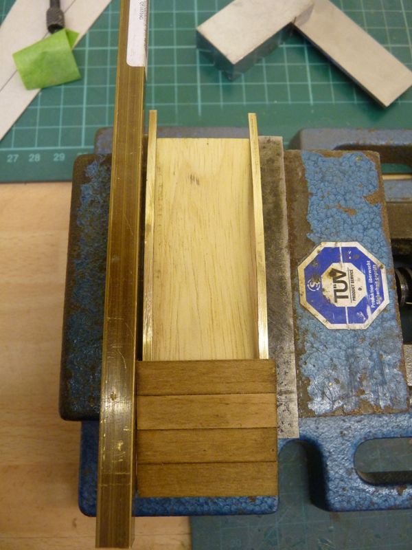
                                                    I made a suitable jig to hold the two supporting beams for each hatch cover with a piece of ply to act as a spacer while the boards were glued on. The piece of brass strip on the left hand side is an aid to getting all the board edges in line.

                                                    spider 167.jpg

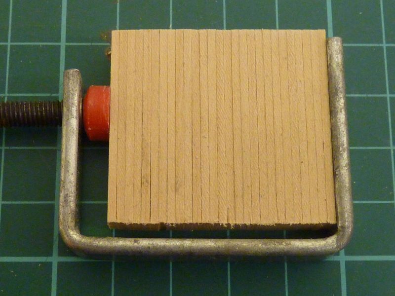
                                                    For each hatch all the boards were cut from some 8 mm wide, 1 mm thick lime planks and dyed a suitable weathered brown. They were all sanded to length as a block to ensure they are a consistent size.

                                                    spider 166.jpg

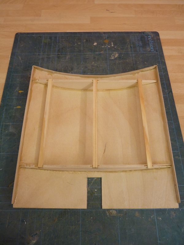
                                                    I have also made the front 'working/sailing hatch from 1.5 mm ply sheet with 3mm play formers and 6 mm square longerons. The side pieces are 0.75 mm ply and will sit in the recess of the cleats attached to the side of the coamings.

                                                    spider 169.jpg

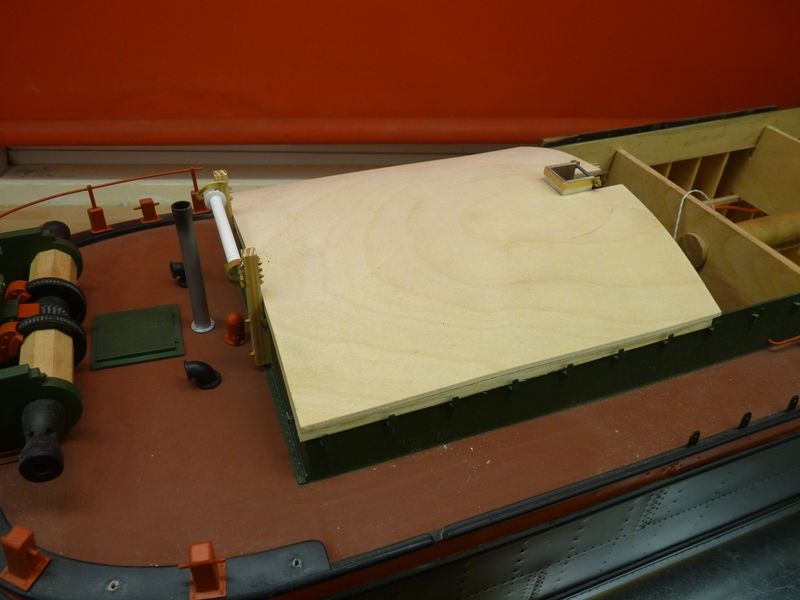
                                                    The picture below shows an initial fitting and in the end, this hatch will probably finish flush with the front of the mast. The reason for this is that it has to be able to be fitted and removed under a sheet horse that crosses the hold just forward of the mast and is attached to the coamings on either side.

                                                    spider 168.jpg

                                                    At this stage I have not yet made up my mind on the full working/sailing hatch cover layout but it will probably have three sections, front, back and an easily refittable centre section over the lifting handle so the cover can be fitted once the boat is in the water. I also want to be able to display the boat with one or two of these working covers removed with the 'proper' hatches visible on one area and a simulated cargo in the hold in an adjacent area. Exactly how I am going to do this still remains to be decided. The hatch covers will be secured by magnets positioned at suitable locations.

                                                    On the real vessel the hatch covers and tarpaulins are secured by steel bars and wedges in the cleats. Since I don't fancy having to fit about 60 wedges every time I replace the hatches these will actually be glued to the simulated steel bars and tarpaulin on the hatch. The tarpaulins will be simulated with some dark green Solartex material.

                                                    Now back to pondering how and where to join the hatch sections.

                                                    Gareth

                                                    #75420
                                                    Gareth Jones
                                                    Participant
                                                      @garethjones79649

                                                      I made a decision on the hatches and have shortened the front one so that it finishes flush with the fairlead where the sheet for the foresail emerges just in front of the mast. The reason for this is that there is a fixed deck horse across the hatch at this point and, if I had left the front hatch as it was, it would be very difficult, if not impossible to fit behind the front winch and under the deck horse.

                                                      I have now made the rear hatch in two sections. The aft one will normally be semi permanently fitted and the centre section gives access to the carrying handle and will have to be fitted after the boat is in the water.

                                                      spider 170.jpg

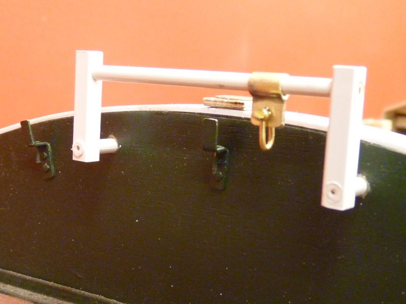
                                                      The next step should have been to fit the magnets to hold the hatches down but since they are still in the post I made the foresail deck horse as shown below. It is made from 1/8 inch brass rod and is attached by two short strips of brass through each side of the hatch coamings. The deckhorse slides in through a hole in each strip, which is free to float sideways at present to allow everything to line up. The brass strips will be secured in their final position with some epoxy resin on the inside of the coamings.

                                                      spider 171.jpg

                                                      As another fill in job I have made the main sail horse from 3 mm styrene rod and 4 mm square tube. The slider is a bit of brass tube and strip. Now that I know it fits, it needs final sanding and gluing before painting, This will not actually be used when sailing the model so it does not need to be particularly strong.

                                                      spider 172.jpg

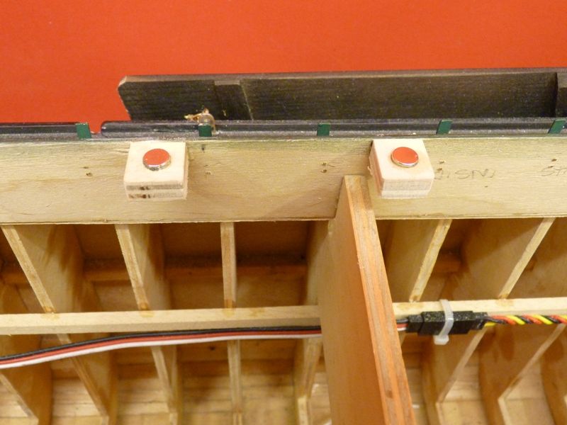
                                                      The magnets have now arrived so have been attached to the inside of the coaming using 6 mm thick ply drilled out to take the 6 mm diam, 3 mm thick magnets.

                                                      spider 173.jpg

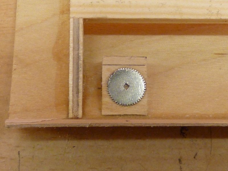
                                                      The steel targets for the magnets are attached to the underside of the hatches on a tapered packing piece. I originally planned to use some small steel washers as targets until I discovered stainless steel is not magnetic. I happened to have a tin full of bits of watch components and managed to find some suitably sized gear wheels, about 10 mm diameter which make a good substitute.

                                                      spider 174.jpg

                                                      The next job on the hatches, now that they are tied down in their correct positions, was to fair in the joints so that there are minimal steps and gaps between each one.

                                                      Gareth

                                                    Viewing 25 posts - 126 through 150 (of 201 total)
                                                    • Please log in to reply to this topic. Registering is free and easy using the links on the menu at the top of this page.

                                                    Code of conduct | Forum Help/FAQs

                                                    Latest Replies

                                                    Home Forums Scratch build Topics

                                                    Viewing 25 topics - 1 through 25 (of 25 total)
                                                    Viewing 25 topics - 1 through 25 (of 25 total)

                                                    View full reply list.