
Spider J

Spider J

Home Forums Scratch build Spider J

  • This topic is empty.
Viewing 25 posts - 76 through 100 (of 201 total)
  • Author
    Posts
  • #55060
    Gareth Jones
    Participant
      @garethjones79649

      Bob,

      Chains might look authentic but since there were no chains on the original keels and sloops, they would not really be authentic. In more recent times some keels and sloops have been modified to have a wheel house with a chain connecting the wheel to the rudder but Spider J is intended to be representative of an old keel with just a wooden tiller arm.

      Thanks to everyone who has suggested possible solutions. I now do have an idea using two plastic covered stranded steel cables running just below deck level but I need to check a few things out first. When I have looked at the model again tonight I will do a sketch.

      With regard to the plating I quite like Bobs idea of thin aluminium from drinks cans as it should take the rivet impressions quite well and be unlikely to deteriorate in the water. I dont think PVA glue will be suitable though. My understanding is that it sets as a result of the water content soaking into the wood and bonding the parts together. Since both the aluminium and fibreglass coating will be impervious to water, I think the glue would only set around the edges where it would be able to dry out. There probably will be something suitable but it needs to have a reasonable about of working/lining up/repositioning time, but since clamping the sheets to the side of the hull will be difficult on the curved areas, I dont want to have to stand all night holding a sheet in place till it grabs.

      Gareth

      #55061
      Bob Abell 2
      Participant
        @bobabell2

        I would do a sample, and see how it behaves?

        Bob

        #55065
        Kimosubby Shipyards
        Participant
          @kimosubbyshipyards

          Gareth

          unless you have access to specific water proof double sided tape, don't use it. I created a nice poly foam hull by sticking the foam lengths together, Z-poxyed it (not well enough obviously) and used the hull for some time until if fell apart along one of the taped joins. Must do better sealing jobs.

          Kim

          Edited By Kimosubby Shipyards on 12/01/2015 13:56:30

          #55170
          Gareth Jones
          Participant
            @garethjones79649

            Its funny how ideas sometimes come to you by chance, triggered by some random event. I was looking for a bit of brass strip in my scrap box and came across a piece bent through two right angles which was a rejected part of a yacht vane steering mechnism I built last year. It dawned on me that I could use a similar arrangement to drive the tiller on Spider J. My proposed solution uses some of the ideas put forward by Kim and Dave but sadly Bob, no chains.

            spider 48.jpg

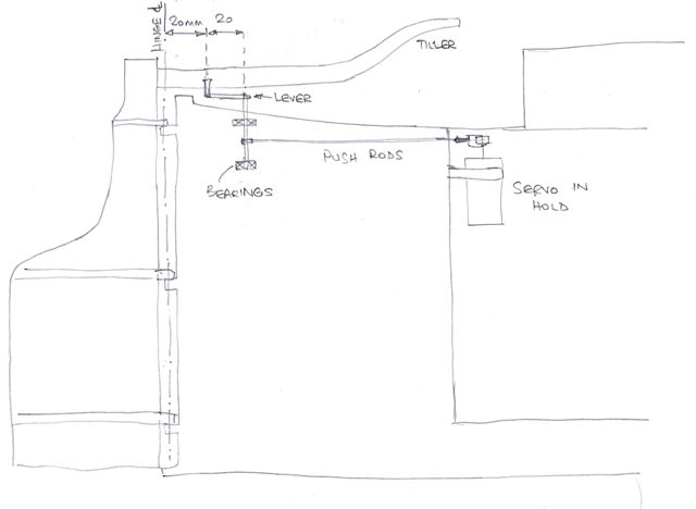
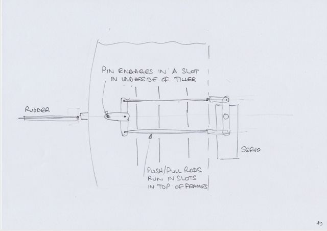
            I propose to mount the servo at the top aft end of the cargo hold where it will be accessible. It will drive a pair of horizontal closed loop push/pull rods which will sit in slots in the frames, just below the deck level. Approximately 40 mm forward of the rudder hinge line will be a vertical shaft carrying a matching pair of levers to which the push/pull rods connect. The shaft will be supported by a pair of plain bearings and extend up through the deck through a hole sealed by a close fitting grommet to keep out any water.

            spider 49.jpg

            Just above the deck level and directly under the tiller will be another 20 mm lever attached to the vertical shaft. This lever will run fore and aft and at its aft end will support a vertical pin that engages in a slot in the underside of the tiller. I will fit a slotted brass strip to the underside of the tiller to provide a bearing guide for the pin, rather than rub directly on the wooden sides of the slot.

            The proposed solution is quite neat, if a bit fiddly. However it avoids any holes in the stern near the water level, gets the levers away from the hull skin and hides the visible parts of the drive mechanism pretty well under the tiller.

            Thanks for all the suggestions and ideas, they all help to come up with a solution. I have always found designing things from scratch to be very difficult and a blank piece of paper is pretty frightening. But show me a drawing or suggest a mechanism and I can understand it and develop it pretty well, after all that's been a large part of my job for the last 40 years.

            Now I just have to get on and make all the bits and fit them in the boat.

            Gareth

            Edited By Gareth Jones on 16/01/2015 09:27:13

            #55172
            Kimosubby Shipyards
            Participant
              @kimosubbyshipyards

              Gareth,

              That'll do nicely on my thames barge too so consider that set-up copied by me before you copyright the idea. The difference will be I'll top the vertical rod with a another T and have push/pull rods to the rudder stock as there is no tiller bar to use. In effect duplicating the arrangement on the servo.

              The only hole in the deck is the vertical rod and that can be sealed with a grommet.

              Clever idea, thanks, aye Kim

              #55175
              Dave Milbourn
              Participant
                @davemilbourn48782

                Gareth

                Very neat, m'duck. I've drawn out the parts on AutoCAD and found that with the geometry you have shown you will get approx 24° rudder deflection for 30° of servo movement from neutral. Kim will be able to say if he thinks this is enough. My only concern is that the pin must be pretty close fit in the slot under the tiller arm or there will be a lot of slop around neutral.

                Dave M

                #55189
                Kimosubby Shipyards
                Participant
                  @kimosubbyshipyards

                  DM and Gareth,

                  my old barge has rudder deflection of 36 to port and 30 to starboard. Gareth has seen her abilities in all weathers, so 30 would be fine.

                  To get a bit more, instead of the lever holding the tiller engagement pin pointing aft, it could point forward and be a bit longer, or just move the whole shaft foreword 5 mm and get a bigger rudder angle that way.

                  Aye, Kim

                  #55685
                  Gareth Jones
                  Participant
                    @garethjones79649

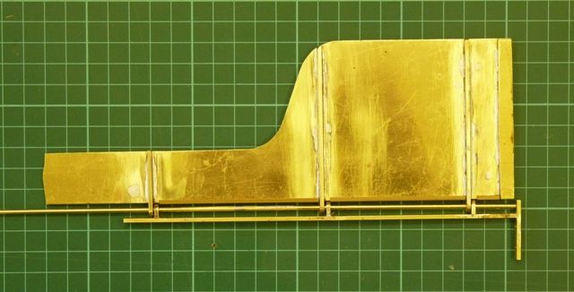
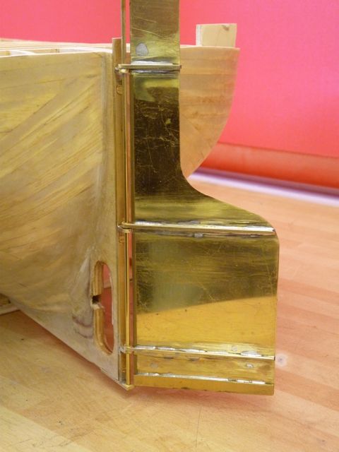
                    After a few hours spent with a blowtorch, solder, hacksaw, files and assorted bits of brass the rudder and the hinge post have materialised.

                    spider 50.jpg

                    The top part needs shaping and trimming to fit a short length of box section in which the tiller will be located. However I wanted to fit the whole thing on the hull before cutting the top to shape.

                    spider 51.jpg

                    I am now contemplating a different way of driving the rudder, based on a more conventional pair of levers attached about 15 mm down from the top. These would connect to the rudder servo by a closed loop pair of wires which would run throuh a pair of plastic tubes from the stern to the hold. The tubes would slope downwards as they run aft to minimise the amount of water which might get splashed through the tubes in rough weather or when going astern under motor power. If Spider J starts going astern when under sail it will really be in trouble.

                    I am just awaiting the delivery of a couple of turnbuckles with which I plan to make the rudder levers and mock up the arrangement before starting to drill holes in the hull and rudder.

                    Gareth

                    #58288
                    Gareth Jones
                    Participant
                      @garethjones79649

                      Progress on Spider J has been very slow for the last few months, mainly due to a rush on yacht jobs, including fitting radio, rudder servo and sail winches in four different yachts and resurrecting four model aircraft by fitting 2.4 GHz radios in lieu of 35 MHz, with all the associated reprogramming of control throws and mixes.

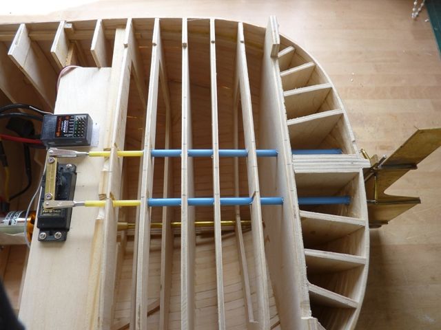
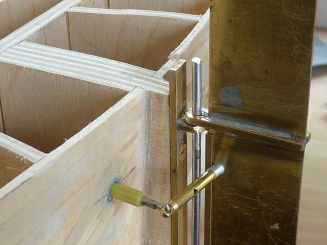
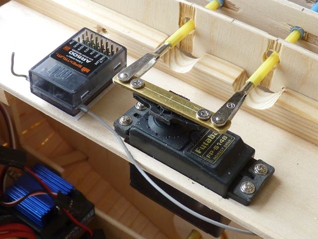
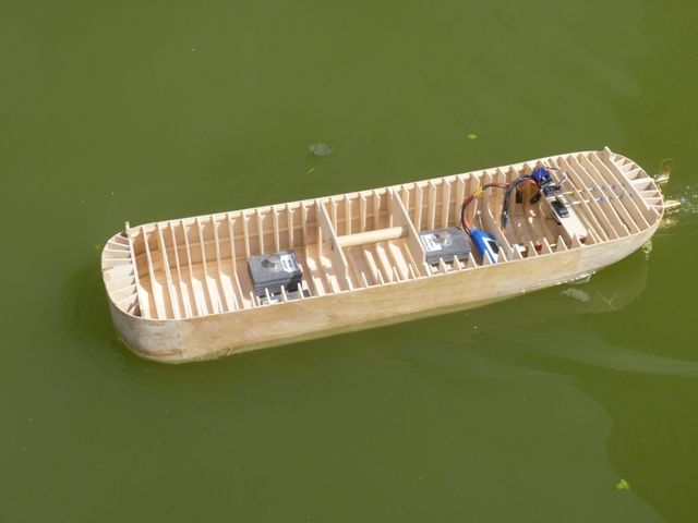
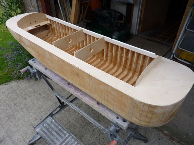
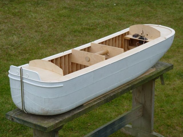
                      However the imminent arrival of the CADMA Northern Model Boat Show last weekend spurred me into action and I managed to get the rudder control installation completed in Spider J and the prop shaft fitted. The rudder control is not exactly as I previously planned but is instead based on a couple of 'snakes' fitted between the servo and rudder. They run through the last few frames and the holes had to be drilled using a file in an electric drill, because of the depth of drilling required. This was a bit messy and splintered the ply but it will all be hidden under the deck in the end.

                      spider 52.jpg

                      spider 53.jpg

                      The turnbuckles which form the links are attached to the rudder by a short length of threaded rod and an angled spacer so that the connections to the snake are in line through the rudder pivot shaft.

                      spider 54.jpg

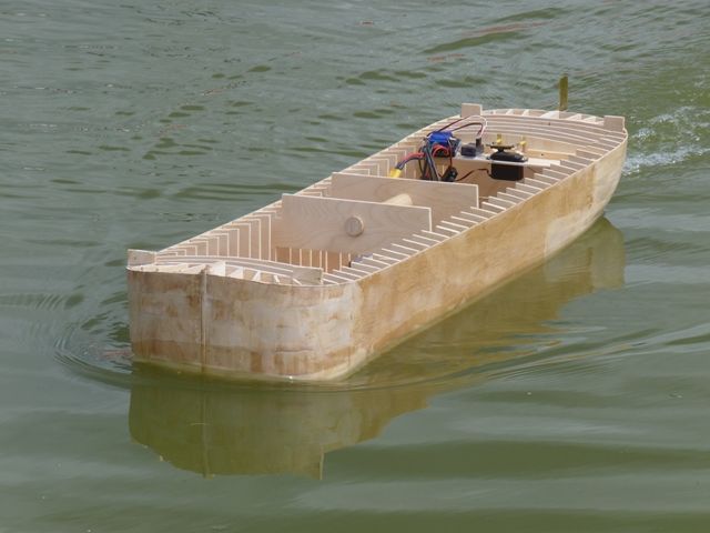
                      After fitting the prop shaft Spider J had an outing to Goole this morning to check out the performance on the water. This revealed a couple of major problems in that the brushless motor was very noisy and had fairly coarse control at low rpm. I think the end result is going to be that I will convert to a trusty Graupner Speed 700 brushed motor, assuming it will fit in the space.

                      However performance of Spider J was pretty good at low power, cruising around very nicely and with a reasonable turning circle at full rudder.

                      spider 55.jpg

                      I borrowed Shemarah's ballast weights for the occasion. I think I will also use them in the long term, supplemented with some fixed ballast attached between the frames along the bottom of the hull.

                      spider 56.jpg

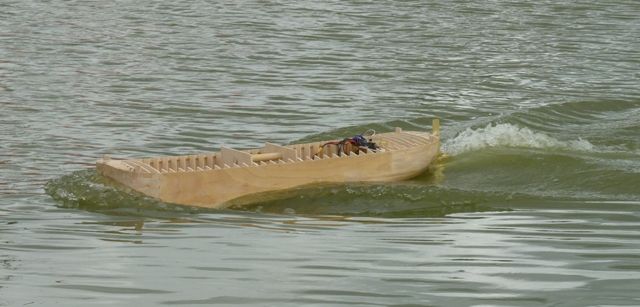
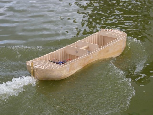
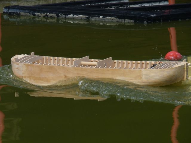
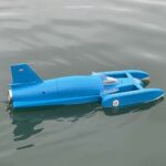
                      At full power with the brushless motor there was ample thrust and the following couple of photos show it is possible to drive even a model of a 90 year old barge like a hooligan. It makes even bigger waves than Shemarah.

                      spider 57.jpg

                      spider 58.jpg

                      #58291
                      Dave Milbourn
                      Participant
                        @davemilbourn48782

                        Maybe the 700 is a better choice, Gareth.

                        DM

                        #58295
                        Bob Abell 2
                        Participant
                          @bobabell2

                          Very nice, Gareth

                          I`ll bet you are glad now, that you retained all those bulkheads?………They look very impressive

                          The blunt bows look nice too, being a POF structure

                          Is the horizontal propshaft watertight?

                          Bob

                          #58347
                          Amy jane September
                          Participant
                            @amyjaneseptember49770

                            Hi there Gareth

                            Good to see an update, I'd been wondering…

                            Great to see her on the water, The photos are a great illustration of wave making, and how a full bowed boat settles bow down when pushed hard!

                            Aj

                            #58350
                            ashley needham
                            Participant
                              @ashleyneedham69188

                              Gareth. Very nice. Not overpowered at all….

                              It is handy to have some long series drills in the old box, for issues like your rudder control runs. i think I have one 5mm one!! but once you have a hole, its then easier to get a file in there to enlarge.

                              Shame to paint that shiny rudder.

                              Ashley

                              #58573
                              Gareth Jones
                              Participant
                                @garethjones79649

                                Dave – you're right

                                Bob – No leaks anywhere

                                Amy – Glad you like it

                                Ashley – The rudder will be painted matt black eventually

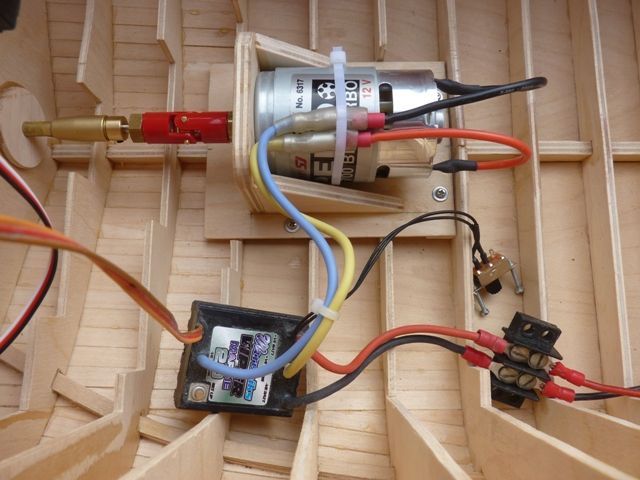
                                Thanks to a very speedy delivery from Cornwall Model Boats (ordered Tuesday evening, arrived Thursday morning, Spider J has a new motor. Reverting to a Graupner Speed motor may seem a backwards step to the technophiles but fortunately there was a suitable model in their now much reduced range, which seemed to fit the bill, a Speed 700 BB Turbo, part number G6317.

                                According to the Graupner datasheet the diameter was 44 mm which looked like it would just clear the keel as long as I made a special mount to get the axis as low as possible. That way I could avoid having to remove and refit the propshaft.

                                The Graupner performance figures are no load speed on 12 volts, 11600 rpm, no load current 2 amps, max efficiency current 12.5 amps, stall current 43 amps.

                                A new mount was made up from 6 mm ply uprights on a 3 mm ply base, The diaphragm that supported the brushless motor was cut away and three frames cut down to be flush with the top edge of the keel. The ply base is screwed to 4 bearers that are glued to the frames. A thin piece of card was necessary to shim up the base plate so that the propshaft lined up. Here's a picture of the new motor fitted along with a slaved in Mtroniks 20 amp speed controller.

                                spider 59.jpg

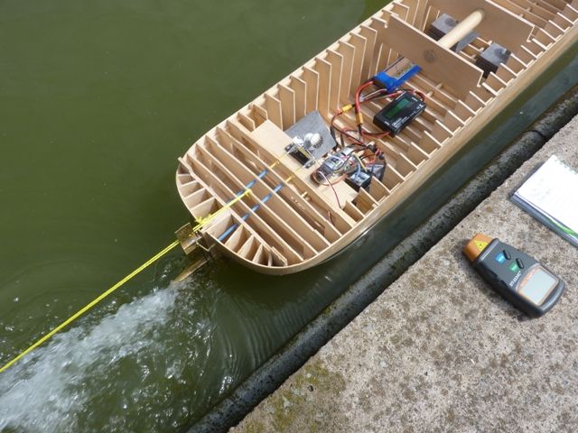
                                The installation was taken to Goole on Monday for testing in the usual way and here's a picture of the test set up with Spider J harnessed to the shelter on the pondside. Note the wattmeter connected between the battery and speed controller and tachometer ready on the pond side to read prop rpm.

                                spider 60.jpg

                                Unfortunately my 'thrustmeter' would not perform on the day as several of the LCD segments no longer light up so it was impossible to read the correct load value on the fishing scales display. However everything else worked fine so here, for the anoraks among you, are the performance figures.

                                The boat has a 45 mm diameter 4 bladed brass prop, pitch unknown I am afraid. Power supply was a 3S LiPo battery, only because it happened to have the correct connector for the speed controller set up.

                                No load performance with the motor just driving the propshaft and propeller out of the water was 1.8 amps at 12.5 volts, 22 watts and prop speed of 12520 rpm.

                                With the boat tethered, propeller fully immersed in the water and full throttle applied, the current drawn was 16.7 amps at 11.9 volts, 195 watts and prop speed of 9200 rpm. This suggests at full power under load the motor is running at about 75% of the free running speed which is a very good match, particularly since Spider J is not going to be spending much time running under full throttle conditions.

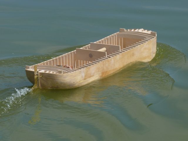
                                Free sailing was fine, almost as fast as the brushless set up. The installation was much quieter, just a bit of 'Mtroniks whine' from the motor at low speed. Here are a couple of pictures to show you what it looks like.

                                spider 61.jpg

                                spider 62.jpg

                                The next step is to add the mast shroud plates to the inside of the hull and any other fittings that will come through the edge of the deck, before I start to build up the deck sections on the hull.

                                Gareth

                                #58894
                                Gareth Jones
                                Participant
                                  @garethjones79649

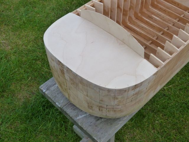
                                  The front and rear sections of deck have now been added, together with the front and rear headledges, all made from 1.5 mm ply.

                                  spider 63.jpg

                                  spider 64.jpg

                                  The ply strips that make up the walkways along the sides of the deck have been cut out, but before they can be fitted I need to install the brass plates to attach the shrouds and the lee boards. The shroud plates will be glued to the inside of the hull skin and bent inwards so that they are effectively hooked under the top stringer for strength.

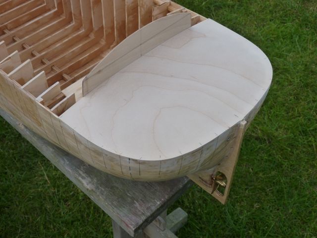
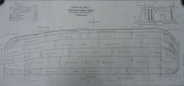
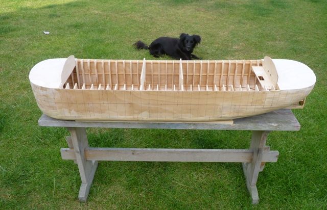
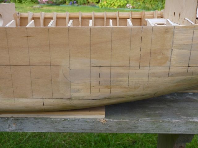
                                  I have made a start on marking out all the hull plating using the original shell expansion drawing as a guide.

                                  spider 67.jpg

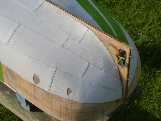
                                  There are effectively 5 rows of plates each side, between keel and gunwhale. The largest, at full size were around 15 feet by 4 feet so at 1:16 scale they are about 285 mm long and 75 mm wide. I am planning to make the plates from 0.3 mm styrene sheet. Luckily A4 sheets of styrene will be just long enough to get the correct length of plate. Hopefully, where there is some degree of double curvature a bit of heat from a hairdryer should allow the material to be shaped. Each plate will have the rivet pattern applied using a suitable tool, yet to be made up, and will be glued on using epoxy resin. The original drawing will be used as a guide to the fitting of each plate so that there are either lap joints or butt joints between them as on the full sized hull.

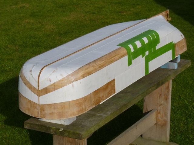
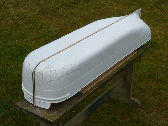
                                  The line of the plates was easy to transfer to the sides of the hull but more difficult at the bow and stern. The appropriate end point was marked in pencil and a length of masking tape applied to get the best line around the curved section which should allow the plates to be fitted with the minimum of twisting or double curvature.spider 65.jpg

                                  spider 66.jpg

                                  The rivets were spaced 3 inches apart on all the lap joints and butt straps and 6 inches apart where they attach the plates to the frames. An unexpected side effect of building the hull with all the frames spaced as on the full sized hull, is that it was easy to mark the position of the frames on the outside of the hull. This will make it straightforward to transfer the position of all the rivet lines on to the individual plates.

                                  When this part of the job is finished I am going to apply for membership of the Rivet Counters Guild.

                                  #58895
                                  Dave Milbourn
                                  Participant
                                    @davemilbourn48782

                                    Gareth

                                    Still looks to be a lot on the fast side of ideal. Have you thought of trying a lower voltage i.e. a 2S LiPo or 6-cell NiMH pack (or even a 5-cell pack)? For a low-speed low-current 12v 700-sized motor there's this as an alternative **LINK**

                                    Dave M

                                    #58930
                                    John W E
                                    Participant
                                      @johnwe

                                      Hi ya Gareth

                                      I have just caught up with this build. Had a good read and thoroughly enjoying it!

                                      Couple of things went through my mind The first one was, I know you are going to use Plasticard for your plating. At this present moment – I myself am rebuilding my model of the Boston Blenheim which I built in the late 1980s early 1990s and for the majority of the upper works – I used Plasticard for the bulwarks, bridge etc. When I was bringing the model down from the loft I knocked it on the side of the hatch – catching some of the plastic which abruptly shattered into lots of bits and also part of the plastic turned to a powder-like substance.

                                      I wont go into too much detail about it.

                                      Anyway, what made me think – is my experience of using the Plasticard as plating on other models – as you are intending to do – which has brought into question the length of life of the Plasticard and all the work you will put into it.

                                      I was originally given a few sheets of printers' Lithoplate (a very thin aluminium) to try that as plating. But, I found, for me to get it to stick successfully to the hull sides (which had been fibre glassed) I had to abrade the contact side of the Lithoplate with emery cloth and I was using Superglue as a bonding agent – as I couldn't get away with using contact adhesives.

                                      Also, my next thought for your wife's build of the barge; have you thought of double-planking the hull? Using a similar method as these Hatchett magazine people do in their Bismark/HMS Hood/Titanic builds. I myself have used a similar build to this on my last hull (Cargo vessel – Troyburgh). The first layer of planking I did as normal; using fillers to fill any discrepancy in the hull and sanded down. The next layer of planking was put over the top so the planks overlapped the joints of the first layer of planking and this final layer of planking was again sanded smoothly and filled with car body filler. Then instead of using fibre glass and tissue to seal the hull I used Z-Epoxy finishing resin without any matting or any woven materials; painted on as you would varnish.

                                      This was allowed to dry and then sanded with wet n dry sandpaper to achieve the desired finish.

                                      Just food for thought for your next build, cos if you do the outer planking neatly you can see and feel it through the Epoxy resin. I have done this style of build on several vessels and they have worked out pretty well.

                                      Last, but not least, you may have already read it – but have you come across the book from Tree to Sea – about the building of a wooden drifter/last of the wooden vessels. It's a very interesting insight into building and it would give you a good idea of how some of the barges/sloops would have been built.

                                      Aye

                                      john


                                      Edited By bluebird on 05/07/2015 18:52:06

                                      #58938
                                      Colin Bishop
                                      Moderator
                                        @colinbishop34627

                                        Going on from what John says, you could use 0.4mm plywood as plating, it's lovely stuff! If you seal and sand one side of the sheet before cutting out the plates you will have no problems with applying a final finish.

                                        **LINK**

                                        Colin

                                        #58945
                                        Gareth Jones
                                        Participant
                                          @garethjones79649

                                          Hi John,

                                          I had not thought about the long term durability of styrene sheet before you mentioned it. I have done a bit of internet research this morning and it seems to be pretty inert and does not biodegrade so I think I will still go for it despite your experience. The material I am planning to use is the Raboesch type rather than Slaters Plastikard, I dont have anything against Plastikard, just happen to have a few sheets of the Raboesch stuff and thought I would stick with one supplier for consistency.

                                          When I get round to building the wooden keel I am planning to double skin it, broadly as you suggest. I have not given it a lot of thought yet but I had imagined applying glass cloth and resin on top of the first layer of timber, in the same process I have used for Spider J. The wooden planks would then be glued on top of the resin coat and given a couple of coats of thinned Zpoxy to finish and seal them.

                                          I Googled the book you mentioned, from Tree to Sea and it looks really interesting and has several excellent reviews. It is a bit expensive, and only second hand copies are available from about £25 upwards but I will definitely aquire a copy as background reading. My main source of reference material, apart from the original drawings has been 'Humber Keels and Keelmen' by Fred Schofield. It has some good drawings of the construction and rigging of wooden keels and a bit of information on sloops. The main reason for building the sloop first is that it should be easier to sail than the square rigged keel.

                                          Colin,

                                          I had not considered plywood as a plating material but I guess it might be easier to stick to the resin coat on the hull since it will be slightly porous and give the adhesive a rougher texture to bond on to. How would it take the impression of the rivets though? I have tried a few experiments with thin styrene sheet and that seems to work well. I have not tried thin plywood but I imagine the grain might tend to splinter rather than just give a clear dome headed rivet effect. The other advantage of the thin styrene is that it is translucent so that it is easier to transfer the rivel line locations on to it.

                                          Gareth

                                          Edited By Gareth Jones on 06/07/2015 08:01:46

                                          #58949
                                          Colin Bishop
                                          Moderator
                                            @colinbishop34627

                                            There is no doubt that the plasticard (usually Slaters) that we started using back in the 1970s had a short shelf life as I discovered myself, but I would think that modern varieties are a lot more stable. About three years ago I did a bit of checking and found an interesting study by a US museum on the suitability of using plastic card and similar materials for museum exhibits. The conclusion was that longevity depended on the makeup of the material but that ultimately it would fail due to its inherent nature and built in degradation. For this reason it was not recommended for long term use – i.e. many years. How we as modellers can identify which is the long life stuff I don't know! Most materials are subject to breakdown over the long term, you would think glass is pretty permanent but it is in fact a supercooled liquid and will eventually slump within a window frame for example, although it can take hundreds of years to do so. That is why the window glass in old churches is often thicker at the bottom than the top!

                                            With regard to alternative methods of riveting, a common and effective practice used to be to use a hypodermic syringe and white wood glue to apply tiny drops to represent the rivet heads before painting over the surface.

                                            While I use plasticard in my models I do prefer traditional materials which is just as well as I am very allergic to cyano fumes so cannot use superglue which is the usual method of sticking plastic sheet to other materials.

                                            Ultimately people should use the techniques which they are most comfortable with as long as they are familiar with any limitations of the material. (apparently superglue can become brittle and lose adhesion over a number of years!)

                                            Colin

                                            #59125
                                            Gareth Jones
                                            Participant
                                              @garethjones79649

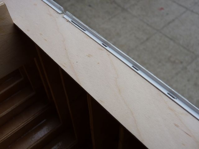
                                              I have now fitted the walkways along the sides of the deck and on one side, the angles where the deck meets the skin plating. The angles are 4 mm Raboesch styrene sections representing the 2 1/2 x 2 1/2 inch section used on the real thing.

                                              spider 68.jpg

                                              Slots have been cut where the shroud plates and mounting for the leeboards will pass through the angles and be attached below deck.

                                              spider 71.jpg

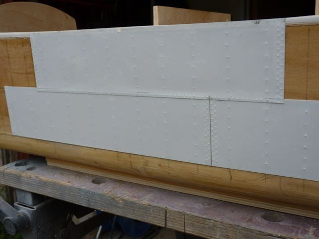
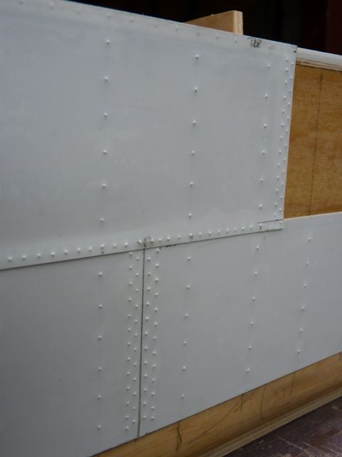
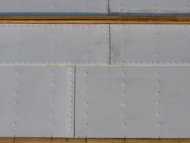
                                              The first few pieces of plate have been added, complete with rivet impressions applied from the back of the sheet. The plates are made from 0.3 mm thick styrene sheet.

                                              spider 69.jpg

                                              spider 70.jpg

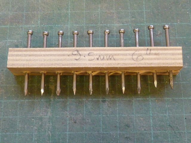
                                              To mark the position of the rivets I made up a couple of tools from pieces of 12 mm plywood with pilot holes drilled at the appropriate spacing, in this case 9.5 mm to represent 6 inch spaced rivets. This particular one was made to produce all the vertical lines where the rivets attach the plates to the frames. Where there is a butt joint as in the picture above the tool is applied twice in staggered positions. A smaller, shorter tool has been used to create the impressions of the rivets joining the skins together along the lap joints between frames. Depending on the length of the section to be marked, some of the nails, which are a tight fit in the holes, are tapped back clear of the surface. To ensure they are all aligned I drew a pencil line on a piece of card and tried the tool out, gently bending any of the nails slightly to get them all aligned and equally spaced.

                                              spider 72.jpg

                                              I found it was best to go over all the impressions afterwards with a pointer with a sharp but slightly rounded tip to get a uniform impression at each location. The plates have been glued on using slow setting epoxy resin, held in place with masking tape while the glue sets overnight.

                                              I have had a first attempt at shaping a piece of styrene sheet to one of the double curvature sections on the front part of the bilge area. I taped a scrap piece of sheet in place and then used a hair drier to heat it and try and persuade the sheet to take up the shape of the hull. However this was not a success, I could not get the sheet hot enough. I plan to have another go with my daughters hair drier which is a bit more powerfull, when further supplies of styrene sheet arrive.

                                              #59147
                                              John W E
                                              Participant
                                                @johnwe

                                                hello Gareth

                                                I promise I will keep me fingers off the keyboard after this and let you get on with your build. But, I like the new tool for producing rivet marks – another thought is using an old clock gear wheel mounted in an old file hand to produce the rivet marks in the Plasticard.

                                                If you cant get the correct spacing for the rivets what you can do is file the teeth away on the cog between the spacings that you require.

                                                I know I used to get my old clock cogs from a flea market in Shields – I used to go round and there were one or two stalls that had old bits of clocks on.

                                                aye

                                                john001.jpg

                                                #60655
                                                Gareth Jones
                                                Participant
                                                  @garethjones79649

                                                  Progress has been fairly slow over the summer as, although I am retired again, there always seem to be lots of distractions including holidays, gardening, model yacht stuff and lots of other odds and sods. However with the imminent prospect of returning to work again over the winter I have managed to find time to get some more plating done on Spider J. There are now only 17 of the 62 plates left to fix and the general impression can be gained from the picture below.

                                                  spider 73.jpg

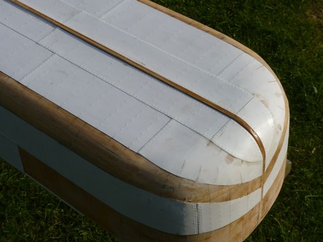
                                                  The method I used has worked quite well apart from the areas where there is a double curvature and I have had to cut some thin triangular sections from the plates to get them to seat reasonably well. I have found that stretching the plate over the curved edge of an old table spoon allows me to form a reasonable degree of double curvature for some areas, without resorting to slitting the plate. Where the plate has been slit I have had to sand down and use some filler so there will be some areas where the rivets will need to be added later.

                                                  spider 75.jpg

                                                  There has been the odd area where I got a bubble under the plate because the glue did not bond to the hull. I have had to cut these out and fill them, followed by sanding and adding the missing rivets. I plan to try the drops of PVA method to add the rivets required.

                                                  spider 74.jpg

                                                  Overall the effect of the plating and rivets looks very convincing and the process seems to work well at this relatively large scale (1:16) The thickness of the styrene sheet is 0.3 mm which would be 4.8 mm at full size (3/16 inch) which is close to the thickness used on the full sized sloop. I suspect if the scale of the model were much smaller it would start to look rather clumsy. Here is a section in the bottom of the hull showing a couple of lap joints.

                                                  spider 76.jpg

                                                  Before I can complete the top level of plates adjacent to the deck I need to add the gunwhale angles around the bow and stern. There are a few other detail parts that mate with this at the front so I am just in the process of making these as a bit of a diversion from measuring and pressing rivet impressions in the plates.

                                                  Gareth

                                                  Edited By Gareth Jones on 03/10/2015 19:36:27

                                                  #60662
                                                  Amy jane September
                                                  Participant
                                                    @amyjaneseptember49770

                                                    Looking good Gareth.

                                                    I can well imagine that the full sized hull would have been a bit of a mission to plate!

                                                    #65464
                                                    Gareth Jones
                                                    Participant
                                                      @garethjones79649

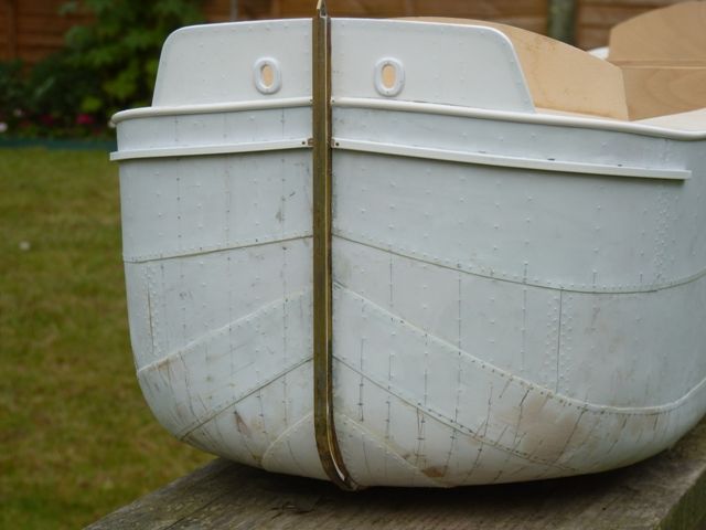
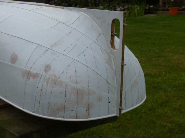
                                                      After a break of about 6 months while have been back at work and occupied with another project I have finally made a bit more progress on Spider J. The hull plating is complete with all the filling rubbed down and the missing rivets added.

                                                      spider 77.jpg

                                                      spider 78.jpg

                                                      The stem, made from 2 brass channel sections soldered together back to back has been added. Its attached by three brass pins into the underlying ply and glued on with Araldite epoxy.

                                                      spider 80.jpg

                                                      The hawse plates have been added and I have made a start on the rubbing strips, one around the edge of the deck and the first of three pairs on the bows. I have yet to add an angle either side of the bow strips, just waiting for a delivery from Cornwall Model Boats as the ones I bought originally at 3 mm were too small and 4 mm was too big.

                                                      spider 79.jpg

                                                      The stern has also been plated, including the rudder skeg. Once all the rubbing strips have been added the hull will get its first coat of primer which will no doubt show up all the blemishes and riveting errors.

                                                      I have also made a start on the anchor windlass and called to take a few pictures of the appropriate bits of Amy Howson's windlass on the way back from Lincoln this afternoon.

                                                      Gareth

                                                    Viewing 25 posts - 76 through 100 (of 201 total)
                                                    • Please log in to reply to this topic. Registering is free and easy using the links on the menu at the top of this page.

                                                    Code of conduct | Forum Help/FAQs

                                                    Latest Replies

                                                    Home Forums Scratch build Topics

                                                    Viewing 25 topics - 1 through 25 (of 25 total)
                                                    Viewing 25 topics - 1 through 25 (of 25 total)

                                                    View full reply list.