
Venetian gondola build 1 : 6

Venetian gondola build 1 : 6

Home Forums Scratch build Venetian gondola build 1 : 6

  • This topic is empty.
Viewing 19 posts - 1 through 19 (of 19 total)
  • Author
    Posts
  • #6994
    Kimosubby Shipyards
    Participant
      @kimosubbyshipyards

      adapted from plans by Gilberto Penzo, Venice

      #56019
      Kimosubby Shipyards
      Participant
        @kimosubbyshipyards

        At Warwick 2013 my colleague presented his radio controlled rowing boat, complete with dog. Those that witnessed it were quite amazed as almost all the rowing actions were possible by remote control. At the time we thought "what can we do next", then someone suggested a Gondola, and a new project was born.

        The idea is to try and program a suitably converted 'Action Man' into a working gondolier, again fully remote controlled. We decided to split the project, I am to provide the boat, hence the scale of 1:6 to match the figure, Jason will attempt the man, though I'm getting up to speed on the programmable chip side as well.

        Gondolas are 36 feet long and about 4 feet in the beam, so this model is big, bigger than I thought anyway, and it would not look authentic to make smaller with the scale figure (and we need his size to fit the probable gear). Jason has since had his rowing boat highlighted in the USA and via that we have located some suppliers of very sophisticated servo items made just for figure movements. More later.

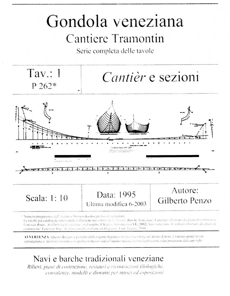
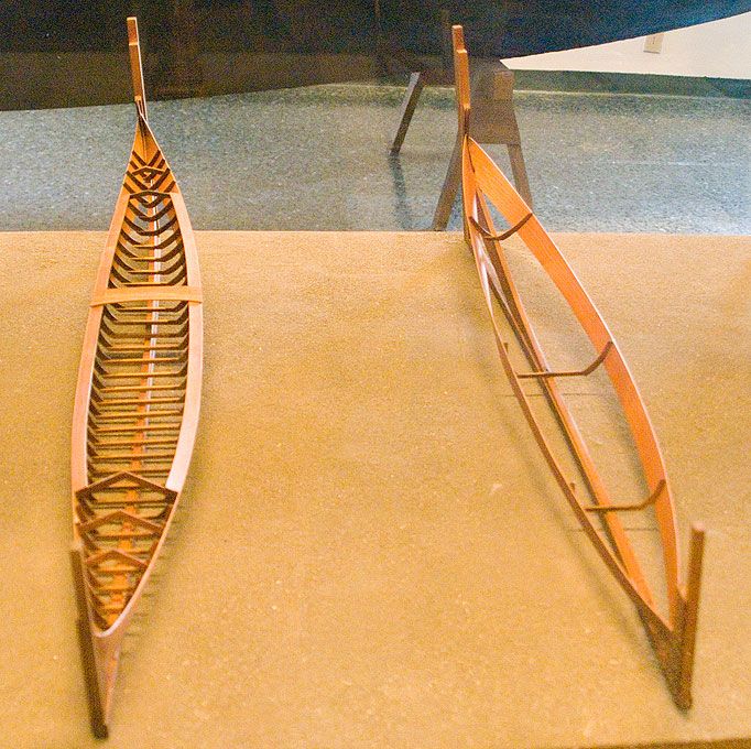
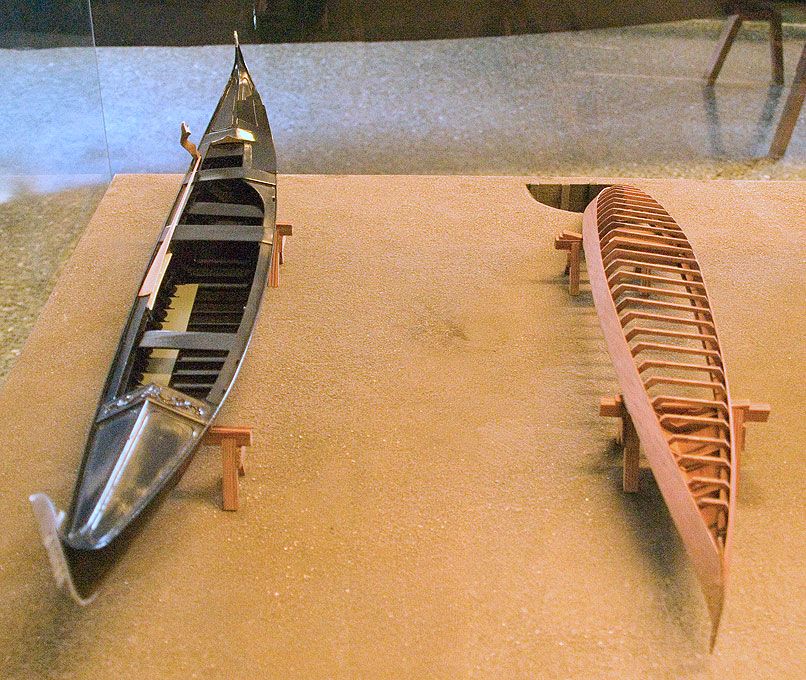
        I tracked down authentic plans from Gilberto Penzo, St Marks Square, Venice and acquired a full set (at 1:10) and a free set @ (1:15) from him. These are used to build the real thing at the Cantiere Tramontin, Venice.

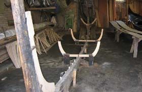
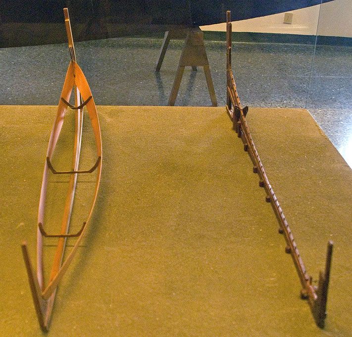
        I have just completed stage one, the construction of the building slipway/frame, which is three dimensional and quite a delight to see. This is called a cantier, and is fundamental to any gondola construction, it has not changed for many decades, and is a fixture in all the gondola cantieres aroung the Venetian lagoon. I struggled due to a lack of Italian, and poor translation of the plan's texts via the web..

        So my first plea, does anyone reading this know Italian phraseology as used for technical drawings and such, or can translate certain Italian terms relating to boat building in general. I am well aware that many of the component parts of a gondola will have their own specific name which may be impossible to translate, but i have, for instance, found some measurements given using the 'once' term, example:

        nerve rovere (Oak) 2 cm 16 x 5 once (14.5 cm). What does once refer to?

        I do have a general arrangement plan that helpfully labels all the main parts, in italian, but due to italian grammar they have differing spellings when in descriptive text, as to when used alongside an arrow.

        I have U-tube videos showing some of the build, but again all in Italian, made by Gilberto. He does not have an english version and our local italians actually come from Sicily and cannot identify some of the words or meanings either as they are not boat builders.

        So if anyone can offer any help I can send them some excel files and lists I've made direct from the plans of words and notes that as yet do not translate into english when entered into an on-line system.

        Try this for instance, aste, there are two of them made of elm or oak, 25 mm planed 20mm, and now made in two pieces

        Enter aste and up comes auctions? And they are not on the parts plan either? I assume they might be the bow and stern posts but????

        Thanks in advance, I'll keep this flowing, Kimmo.

        #56069
        Paul T
        Participant
          @pault84577

          Hi Kim

          I think that the term 'once' refers to the part being made as a single unit, The traditional Gondola is made from 280 interlocking pieces some of which I presume are repeated.

          The term aste is a beam or spar (shaft, pole)

          Paul

          #56083
          Kimosubby Shipyards
          Participant
            @kimosubbyshipyards

            Hi Paul,

            aye, there are a lot of parts to make and it all fits together on that curved slipway about the two asta (rods) and 3 main frames (maestro). All the plans are drawings, there is no table of offsets nor any lines drawings as such, so I cannot loft from them to the scale. There is a template, one of several, for a builders device from which the frames are drawn, but again the explanation of its use is in italian.

            Spent yesterday morning scanning in the frames @ 1/10, then used the computer to size them up to 1/6, all 29 of them. At least I can set them up as per the drawings, most are constructed from three pieces, but, of course, the frame is not symmetrical. I'll pop up the body plan soon. With the frames at the scale size I can now go back to the device and set how it works, a bit like a slide rule, but the marks indicate edges and lengths etc.

            It's fun though, today I'll start mounting them and see what it looks like compared to the body plan.

            Enjoy Russia?

            Aye Kim

            #56088
            Bob Abell 2
            Participant
              @bobabell2

              Hello Kimmo

              You`ve got yourself a real challenge there!

              Looking at the vids on Youtube, the oarsmen have a very strange motion, which may be tricky to reproduce?

              The hull has a special mis-shape to cater for this………It`s lob sided………As you already know?

              Are you having a secret motor drive…..or what?

              Bob

              #56090
              Kimosubby Shipyards
              Participant
                @kimosubbyshipyards

                Hi Bob,

                yes, challenge alright, we now understand that there are about 16 different rowing motions, hence the strange shape of the oar post, the forcola. The hull shape is a nightmare at present, trying to establish a 3D curved centre line to include a 6' pitch to starboard at both ends! Then the plan indicates that the centre master frame is 1' off horizontal, as if you could measure that – or could you?

                Only you would suggest a secret motor drive (clip on submarine type would do nicely) only this beast will end up 6 feet long!

                Aye, Kim

                #56091
                Bob Abell 2
                Participant
                  @bobabell2

                  Hello Kimmo

                  I would like propose a cunning plan, my lord?

                  You could have an underwater track that the oar fits inside, with an oar path and articulate the man somehow and he would follow the underwater track…..With a bit of luck?

                  All these good ideas come free of charge from mainland Britain!

                  Bob

                  #56094
                  Kimosubby Shipyards
                  Participant
                    @kimosubbyshipyards

                    Bob,

                    we have (that's my colleague Jason has) mastered the rowing man, and we have now discovered a website where we can get all sorts of specialised body parts, servos and extras for "Action Man" figures (or what ever they are called in the US). This gondolier will function!

                    Here's the first plan

                    gondola plan 1 of 8.jpg


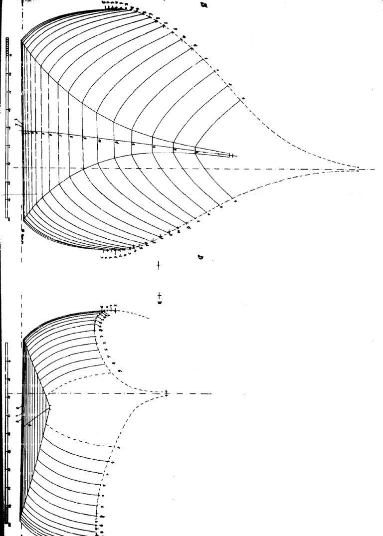
                    and here is the body plan, in two halves through the middle crosswise, with viewing from each end, so a bit unusual for our normal way of displaying such drawings, which are through the middle length wise, from the centre frame.

                    gondola body plan.jpg

                    And to make it awkward for you, it's sideways on too.  I should also state before you ask, the bow is the bottom, shorter stem, without the line of the bow post (asta di prua) shown at a jaunty 6' from the vertical.

                    Aye, Kim

                    Edited By Kimosubby Shipyards on 24/02/2015 12:14:59

                    #56095
                    Bob Abell 2
                    Participant
                      @bobabell2

                      Kimmo

                      My advice to you, having studied the drawings……is to swig three or four Carlsberg Specials before you start and the job will become much clearer?

                      It might even straighten up?

                      Bob

                      #56098
                      mike farrell
                      Participant
                        @mikefarrell21522

                        Well my giddy aunt maybe a further few glasses of Ardmore whiskey.( rocket fuel in my world) will help. Seriously this seem a difficult task ,all the bestfrownMichael

                        #56188
                        Kimosubby Shipyards
                        Participant
                          @kimosubbyshipyards

                          Hi Mike,

                          here's what the first stage should look like –

                          gondolaconstructionstarted.jpg

                          Picture is from bow looking aft. AND no it's not my attic workshop, far too much room here.

                          The build stages are thus, set up build frame, add main frames (3) and fix one plank each side to secure bow and stern posts.

                          sequence_1.jpg

                          Then fill in all the other frames, handily made by a resident carpenter! And add the top rail etc.

                          sequence_2.jpg

                          Then turn over and add more stringers and strengtheners and plank bottom etc, then over again and complete internals and slap on some paint and brass/gold bits to finish.

                          sequence_3.jpg

                          At least the option is there for two oarsmen, but the goal is for a single rower.

                          Gareth has volunteered to provide a sound track of the gondoliers song, no Bob, not the one about ice cream!

                          More will follow, aye, Kim

                          #56190
                          Bob Abell 2
                          Participant
                            @bobabell2

                            Will it be a Gareth and Liz duet?

                            A Welsh male voice choir member with the Yorkshire Lass filling in the high notes?

                            Top Ten potential?

                            Bob

                            #56191
                            Kimosubby Shipyards
                            Participant
                              @kimosubbyshipyards

                              Can see it now – Gareth and Liz seated together singing their heads off whilst Bob and Paul pole them along a canal with Ashley leaning over a bridge parapet offering '99's' at a 1000 lira a go…….

                              Colin, do we have a nightmare thread in the topics listing we can use?

                              Back to the attic, weather has closed in for the weekend as usual, strong winds (gales) and rain – must be Spring in the air.

                              Aye, Kim

                              #56193
                              Colin Bishop
                              Moderator
                                @colinbishop34627

                                I suppose it would have to be the Bridge of Sighs – access all arias….

                                Colin

                                #56204
                                Kimosubby Shipyards
                                Participant
                                  @kimosubbyshipyards

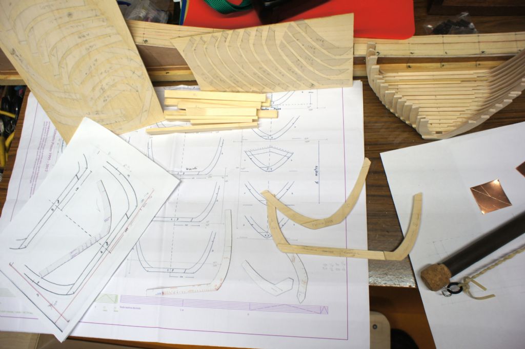
                                  Serious stuff now, here's the start of construction. First problem being that I had no table of offsets so had to rely on the plans supplied at 1/10 scale to be accurate and then copy and enlarge them up to 1/6 a frame at a time. On the original 1/10 plan alongside each farm I drew two line at right angles to each other as datum length lines. From 1/10 to 1/6 the factor is 1.666 recurring, so I used a factorial of 1/10 and 1/6 and as big as could be used when enlarged to A4. The lines on the plan were drawn 150mm horizontal and 90 vertical in pencil, so when enlarged they become 250 and 150 respectively.

                                  framescutandtobedone.jpg

                                  Each frame was scanned into my computer and the file duplicated for a working copy. This was inserted to a word file, and expanded up so that the drawn lines became the dimensions calculated. These are confirmed by drawing lines with the computer and laying them onto the frame image. These lines were in red to be obvious as added by me. Each expanded frame was saved as a separate file and duplicated again. Then printed and checked for size. The loose sheet in the picture is a frame and shows the red lines compared to the pencil lines.

                                  I was going to cut each frame from paper and glue it to the 3.5mm ply for the frames, but looking at the new lines, they were too thick for a decent cut to be followed. So each frame side was traced to tracing paper and then cut out close to the lines and then stuck to the ply. This way I was able to re-draw the shape using the templates from another plan these having already been expanded up to 1/6 size by the method described. These template devices can be seen in the image, one on the A4 sheet, and three on the lower part of the plan. The traced frame sides can be seen at the top stuck on the ply.

                                  framescut.jpg

                                  I now have all the frames from the middle to the bow cut and formed. Two are definitely incorrect in shape on the starboard side, and checking with the plan, it's the plan that has them drawn wrong. Look at the group above, starboard is to the left as you view and counting back from the front frames 3 and 6 are out of line. So I shall re-draw using the template device as I have mostly taught myself how it is used. This is why the offsets table is so handy to check back to. A simple error, the curve taken from the next frame in line by mistake.

                                  hegnerfretsaw.jpg

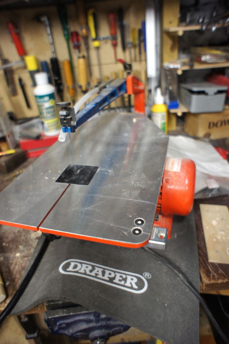
                                  The aft set of frames are drawn and ready to be cut by my trusty Hegner [good plug] fret saw and to be assembled later today or next week. Then its time to set up the slip with the maestro frames and the bow and stern posts and fit the first plank. And that will be a problem as I shall have to join a strip of thin ply to get the length required, about 80inches.

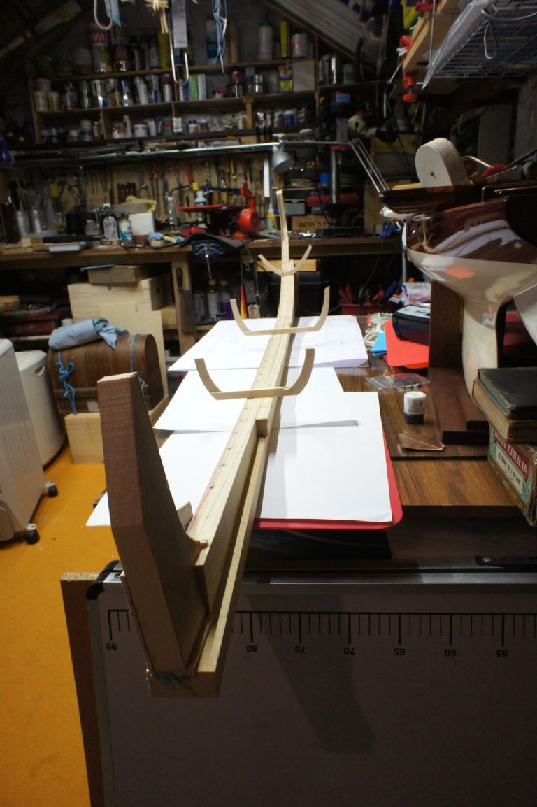
                                  Here's my slip and those maestro frames in place, does it look like that workshop back up the thread?

                                  slipandmaestraframes.jpg

                                  gondolaconstructionstarted.jpg

                                  Till some more gets done, aye, Kim

                                  #56212
                                  Amy jane September
                                  Participant
                                    @amyjaneseptember49770

                                    This is going to be a real interesting project……

                                    #56213
                                    Kimosubby Shipyards
                                    Participant
                                      @kimosubbyshipyards

                                      Hello Amy J,

                                      interesting is the word, this will be quite a challenge to get the build right first time, and at this scale errors will show up too.

                                      Fingers crossed, Kim

                                      #56447
                                      Kimosubby Shipyards
                                      Participant
                                        @kimosubbyshipyards

                                        Gosh, time flies when you're having fun….

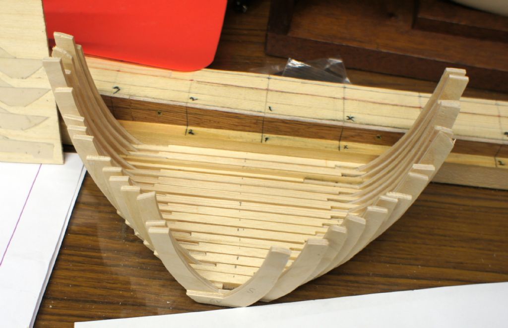
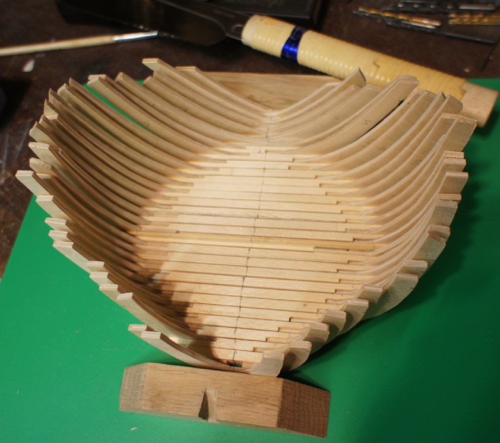
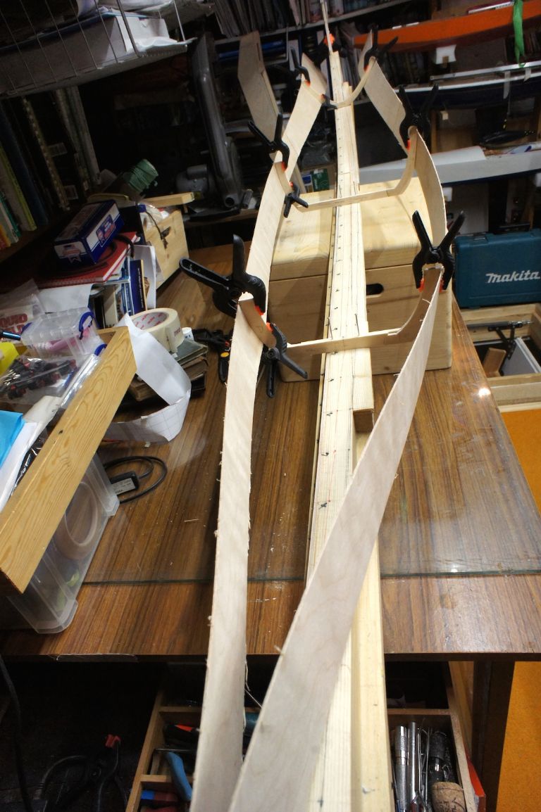
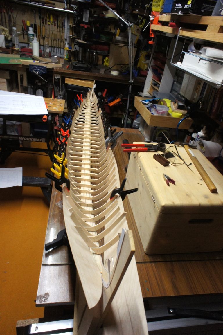
                                        Some progress – all the frames completed and have decided that any re-makes/alterations will be done once I've trial fitted them on the slip with the two master strakes.

                                        allframes.jpg

                                        Looks remarkably like a modern design of fruit bowl – at least I can make use of them if I give up!

                                        Next, having to up scale the given "approximate" main strake shapes from the plans. Here the translation was very helpful in that it stated that all bow and stern shapes are bespoke to individual boats, hence a general shape is given but the builder has the critical task of cutting the strake to fit the bow and stern post so that it creates the hull shape to take the frames. I think that's what it translated as.

                                        masterframesandstrakes.jpg

                                        With just three frames on the slip and the two ends flapping this was not going to be easy. Instead of doing it their way, I will try mine. So I drilled all the frames and positioned them using fine ss horse shoe nails (50mm) which I had been given and they proved their worth. Two can be seen on the 'maestro papa" frame above.

                                        So here's all the frames in-between the two main strakes, and a much better shape and line can be followed. The view is from behind the stern post looking forwards. Now I need to buy more clamps to hold the other side in as well.

                                        allframestrialfit.jpg

                                        The really tricky part is cutting the strake curve to the stern post. I made 4 attempts at this port side, that's four new strakes as I cut too much off each time, or cut the wrong curve. I did manage to get this one right after the photo was taken. Will not glue anything till both sides are clamped and done. Then its the 'mirror dinghy' method drilling holes and using twisted wire to glue and clamp and hold.

                                        At least the shape looks about right, the banana curve, tilt and no twist. They say that after this it gets simpler? we'll see……

                                        Good job I'm your side of the pond this week to get some more clamps.

                                        Aye Kim


                                        Edited By Kimosubby Shipyards on 15/03/2015 16:17:30

                                        Edited By Kimosubby Shipyards on 15/03/2015 16:18:29

                                        #56449
                                        Bob Abell 2
                                        Participant
                                          @bobabell2

                                          Looking good, Kimmo……..Didn`t realise the banana effect was so pronounced!

                                          Why have you made the formers from several pieces of ply?

                                          Is this how the full size frames were built?………True to scale eh?

                                          Bob

                                        Viewing 19 posts - 1 through 19 (of 19 total)
                                        • Please log in to reply to this topic. Registering is free and easy using the links on the menu at the top of this page.

                                        Code of conduct | Forum Help/FAQs

                                        Latest Replies

                                        Home Forums Scratch build Topics

                                        Viewing 25 topics - 1 through 25 (of 25 total)
                                        Viewing 25 topics - 1 through 25 (of 25 total)

                                        View full reply list.