The world's leading magazine for all model boating interests
Eilean Mor
Eilean Mor
Home › Forums › Building Kits › Eilean Mor
- This topic is empty.
-
AuthorPosts
-
26 October 2014 at 17:50 #53072
Banjoman
Participant@banjomanHello all,
I though I might start a build thread to describe my current work in progress (already mentioned in a few other threads), namely the "Eilean Mòr" – a generic (i.e. not based on any specific prototype) Clyde Puffer based on the Mountfleet Models "Highlander" kit.
Before I get going on that, though, perhaps a few words about the builder might be in place?!
My name is Mattias, and I am a middle-aged (born 1965) bloke from Sweden, living in Belgium. In more youthful days, I was a fervent modeller of both plastic kits à la Airfix et consortes and of kit or scratch built r/c model boats.
In my early 20s, though, I gradually abandoned the hobby – not so much for the classic reasons of family and work, but because (a) I got more and more fed up with not having a dedicated space for building (i.e. continously getting work and toools out and then packing them away again after each building session), and (b) my other significant hobby of playing music (I play banjo in trad jazz bands, hence the monniker) took up just about all free time I had beyond getting on with life in general.
However, in 2008 my wife and I were given the opportunity to rent the kitchen part of the old porter's lodge (just one floor down from our apartment) in the block of flats where we live. The initial idea was to use this for extra storage, but I soon realised that it would also make a perfect indoors shed: it has heating, electricity and a sink with warm and cold running water, and thus the thought was born that maybe I ought to give my old love of model boats another spin?!
For my first project, I decided to go with something reasonably small, and also a static model, both to keep initial expense down (my old 4-channel O.S. rx/tx-job had long since given up the ghost) and to help avoid getting stuck part way on too large a project if I found I no longer enjoyed it as of old.
Also, I was quite set upon it being a sort of trial of myself in my own eyes: as a younger modeller, I was too often impatient to get a project finished, and would therefore cut corners left, right and center, with ensuing quality issues in the finished product. In other words I wanted to find out whether or not adulthood had brought the virtue of patience to my personal makeup?
For that first project I settled on HMS Pickle from Caldercraft, and although (for family reasons that I won't go into) it took rather longer than foreseen to finish (almost five years!), I got there in the end, and to my absolute delight found that I had the bug again, and how!
My apologies for the above rant being almost only about the builder and not about the puffer build; amends will – I promise! – be made in the next installment!
/Mattias
Edited By Banjoman on 26/10/2014 17:52:40
26 October 2014 at 17:50 #6169Banjoman
Participant@banjomanBuilding a 1:24 generic Clyde Puffer from the
26 October 2014 at 18:22 #53075 Colin BishopModerator@colinbishop34627
Hi Mattias,
Welcome to the forum, we look forward to hearing your progress. An interesting workshop you have by the sound of it!
I think you are right that as you get older, the hobby becomes more relaxing and you don't mind the time spent to get things the way you want them.
Colin
26 October 2014 at 20:41 #53079Banjoman
Participant@banjomanThank you very much, Colin! And indeed – these days my only real criterion for success or lack thereof in modelling is getting things to where I'm satisfied with result!
So! On to the build … which of course began by deciding what to actually build. For any project, I like to give some thought beforehand to what I want the challenge(s) to be, and this time I knew early on that one such would be to get back to r/c boating, pretty much exactly 30 years on from my last efforts in that direction.
I have also for quite some time been keen to try my hand at airbrush painting, and decided that the time for that would be now.
Taken together, this meant looking for a subject that would be large enough for and otherwise generally suited to r/c (without it getting so large that it would be difficult to handle or fit onto the work top) but also one where the prototype is largely made from metal, as I believe that airbrushing really comes to its forte on what purports to be a metal surface.
One challenge I did not wish to face this time, though, was scratch building, so a kit it would be. Given that I'm generally speaking much more drawn to prototypes pre mid-20th century, and also that I'm more inclined towards civilan vessels, I thus began looking at kits of fishing boats, tugs, smaller merchant ships and similar. I had no previous acquaintance with puffers (their popular culture significance as in Vital Spark, Maggie etc. never made it across the North Sea to Scandinavia), but quickly became drawn to their sort of pug-nosed, cutish charms. I also realised that the hull type would be close to ideal for easy driveline and r/c installation, with two large openings available in the deck and an almost box shaped, very roomy hull interior.
Thus looking at kits, I decided that my third and final main challenge would be a glass fibre hull/white metal fittings-based kit, as I had absolutely no previous experience of that type of construction.
In early 2013, I'd finalised my research and decided to go for the "Highlander" kit from Mountfleet Models, and happily typed their URL into my browser with my credit card at hand, only to discover that they had just suffered a devastating fire!
After some more thought, and getting a very strong impression that they would try their utmost to get back in business, I decided to wait, and in the meanwhile spend the money I'd laid aside for the model (and a bit more) on getting a good quality airbrush and compressor, so as to be ready (and have a bit of practice) on that front when the kit once more became available.
This happy day finally arrived on June 1st 2013, and I promptly put in an order that arrived the following Friday.
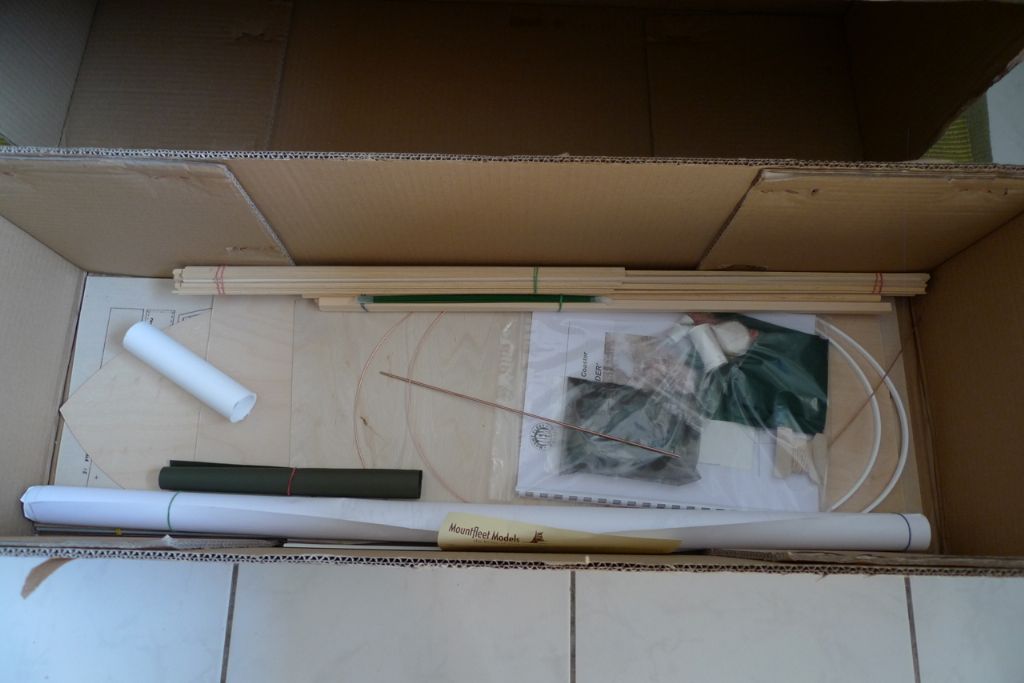
I'm sure you are all familiar with the mix of anticipation and trepidation that comes when one opens a new model kit box for the first time … and this was quite some box, too! In it were plenty of wood and other materials …
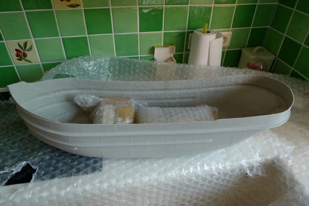
… and of course the hull …
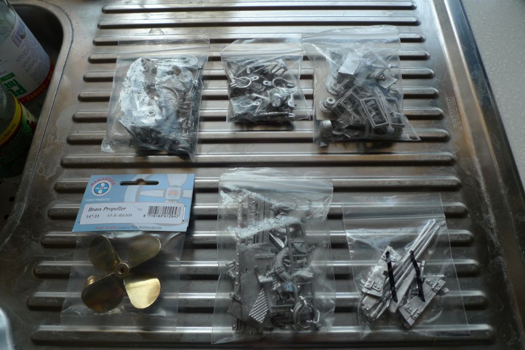
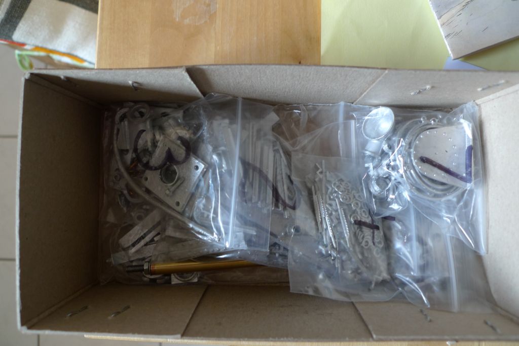
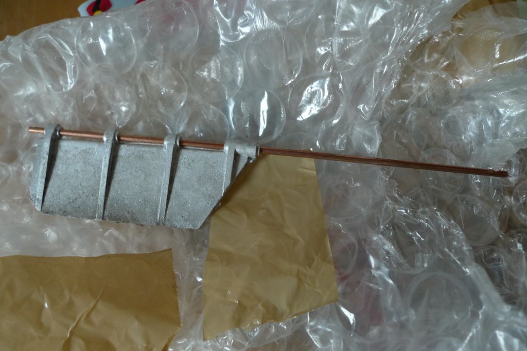
… not to mention plenty and then plenty more white metal fittings:
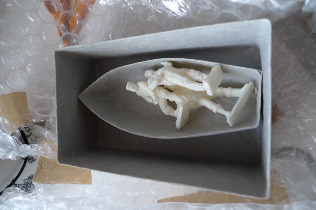
Other than the hull, there were also glass fibre parts for the engine room, the jolly boat and finally three crew members cast in resin.
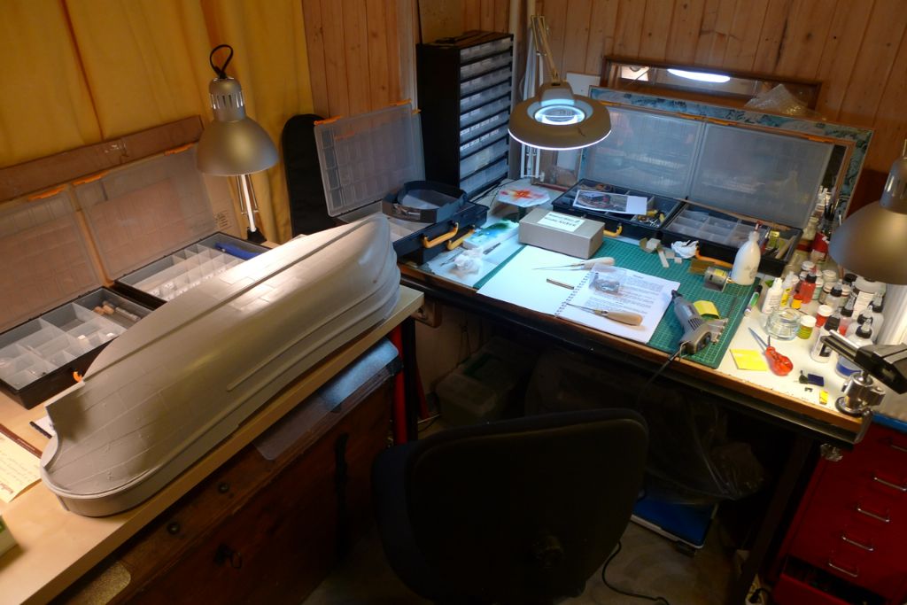
I spent the next couple of weeks just counting parts and reading the instructions backwards and forwards, but on July 1st 2013, having thoroughly washed the hull in soap and luke warm water in the bathtub (and also, as per the instructions, left it to dry connected to ground in order to get rid of any residue static electricity), it was finally time to bring everything downstairs to the workshop …
To be continued …
/Mattias
Edited By Banjoman on 26/10/2014 20:42:35
Edited By Banjoman on 26/10/2014 20:45:03
27 October 2014 at 12:04 #53098Banjoman
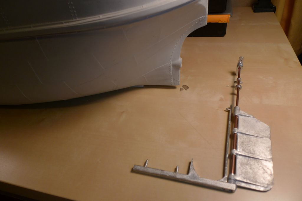
Participant@banjomanThe very first jobs I tackled were to drill the necessary holes in the stern for the skeg, the rudder pintles and the propeller shaft, and also to file down the sternmost section of the rubbing strake to create a free passage for the rudder post.
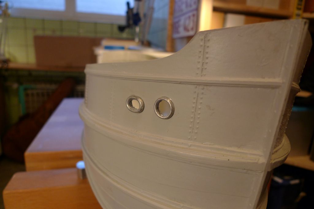
I also drilled for the anchor and hawse holes, and glued their external white metal fittings in place.
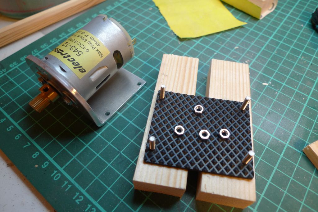
I then prepared the motor installation in the shape of a couple of wood blocks onto which the motor mount could be screwed down, with a small square of rubber matting added to (hopefully) help dampen any vibrations.
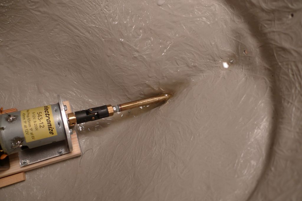
With the motor mount ensemble dryfitted, the propeller axle was glued in place using 24 hour epoxy.
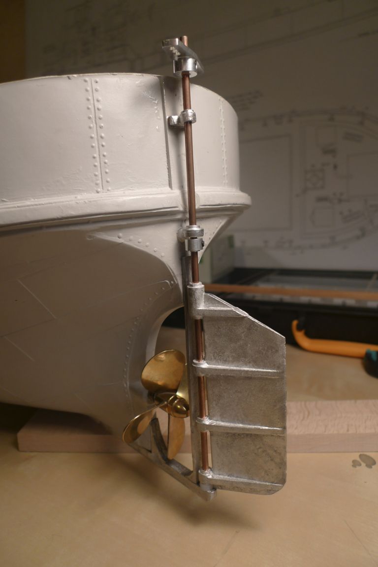
Once the epoxy had set fully, the skeg-and-rudder assembly were up for fixing in place. I was not as happy as I felt I ought to be, though, with the proposed method for fastening this fairly essential piece of kit, and therefore decided to add a few strengthening elements:
- To keep the lower forward edge of the rudder from catching on the outer tip of the skeg, I lifted the rudder a few millimeters with the aid of a couple of nylon washers. These also act as a simple but quite effective form of bearing by producing less friction than white metal against white metal would do.
- To strengthen the bond of the lower pintle to the hull, I cut M3 threads on its shaft, and added two nylon nuts (one inside and the other outside the hull) to the epoxy fastening.
- To keep the rudder from jumping its bearings I screwed a collar onto the post just below the lower pintle.
- Finaly, instead of the rather small, easily bent and hard to properly fasten white metal servo arm included in the kit, I decided on the (perhaps somewhat over-engineered) use of an aluminium double (as my plan was to use two pushrods) servo arm fastened with a stop screw instead.
To be continued …
/Mattias
Edited By Banjoman on 27/10/2014 12:04:22
Edited By Banjoman on 27/10/2014 12:07:37
28 October 2014 at 14:10 #53127Banjoman
Participant@banjomanWith the propeller and rudder assemblies in place, the hull was again watertight, and it was time to check the general ballast needs.
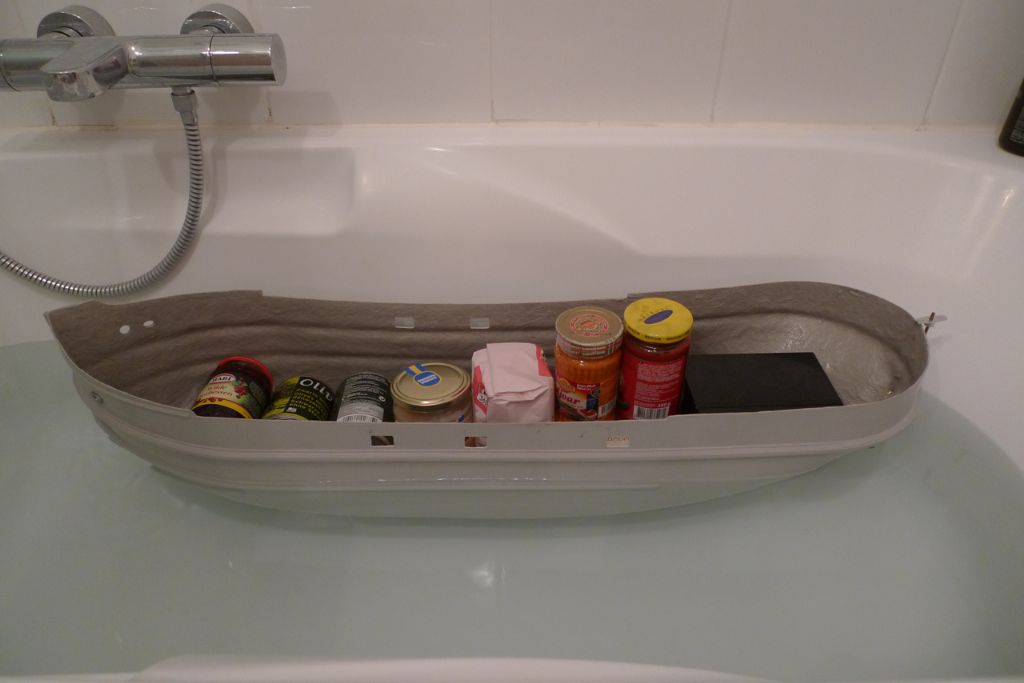
As seen above, I'd opted for an Eletronize 543-12 motor to be run on 6V and for which I'd gotten a 10Ah SLA battery, weighing in at 1,9 kg. The box of white metal parts in its turn provided an additional (and fairly hefty) 1,3 kg, but a bathtub test with a cargo of tins, cans and bags from the fridge and larder made it clear that I would still need to add some eight or so kilos of ballast to get everything down to the approximate waterline!
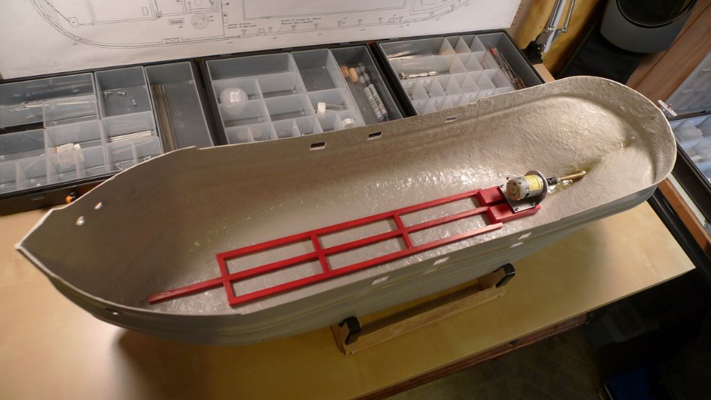
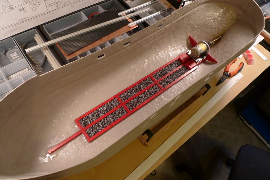
Next up, I built and painted a wooden framework which, together with the blocks under motor mount, was epoxied into place at the bottom of hull. The idea here was to create a "holding pen" for an initial load of lead shot ballast weight at the very lowest point of the hull, but also a framework to which a general fastening system could easily be fixed.
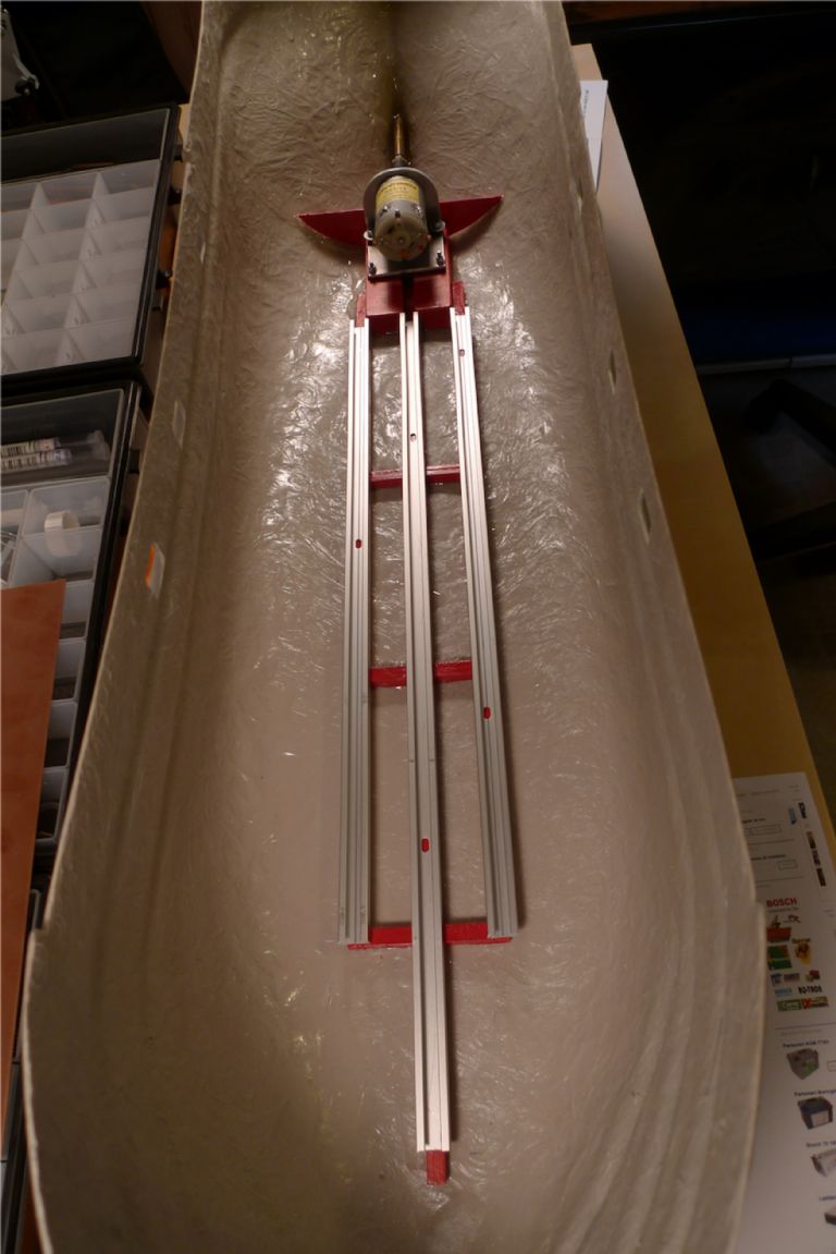
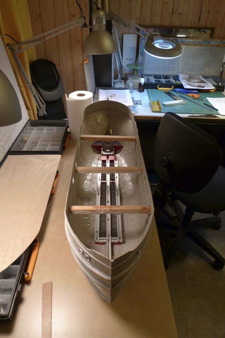
For that fastening system, I decided to go with three lengths of aluminium curtain rod, picked up at a local DIY shop. I also added a low bulkhead aft of the motor mount. The idea here was to create yet another pocket that could be filled with lead shot, both to help bring the stern down properly into the water and to create a vibration absorbant dead weight just below the propeller shaft.
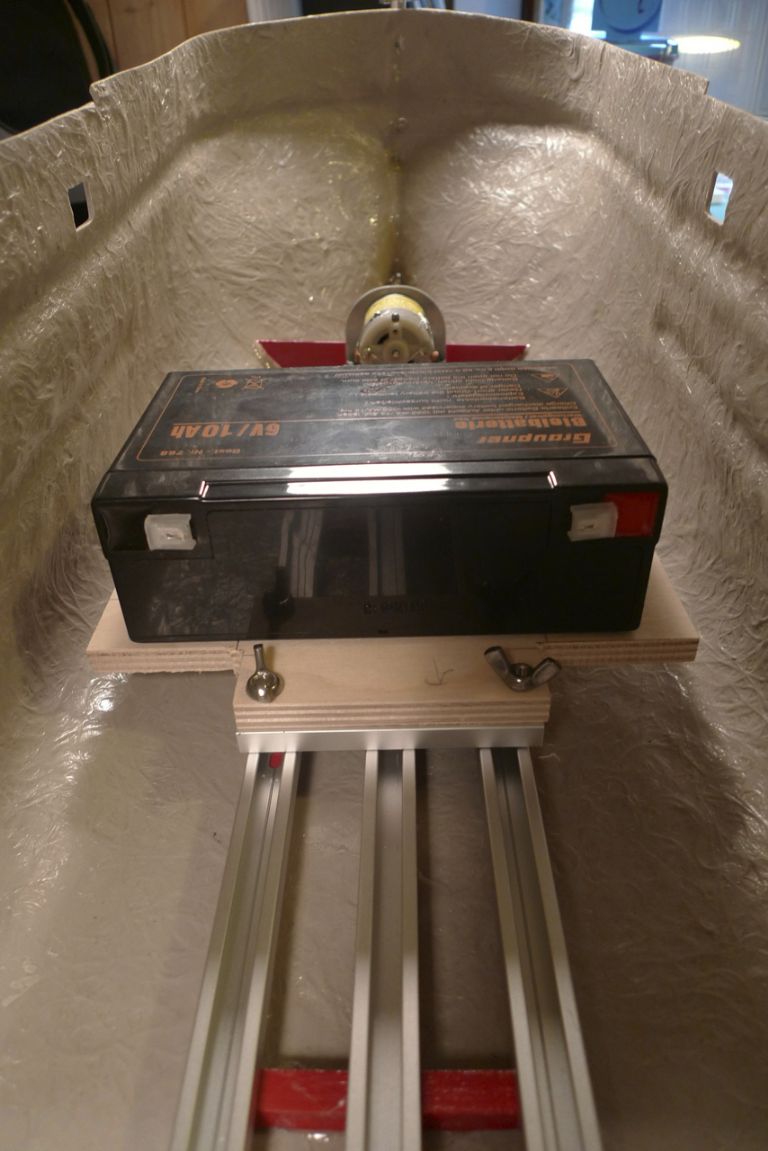
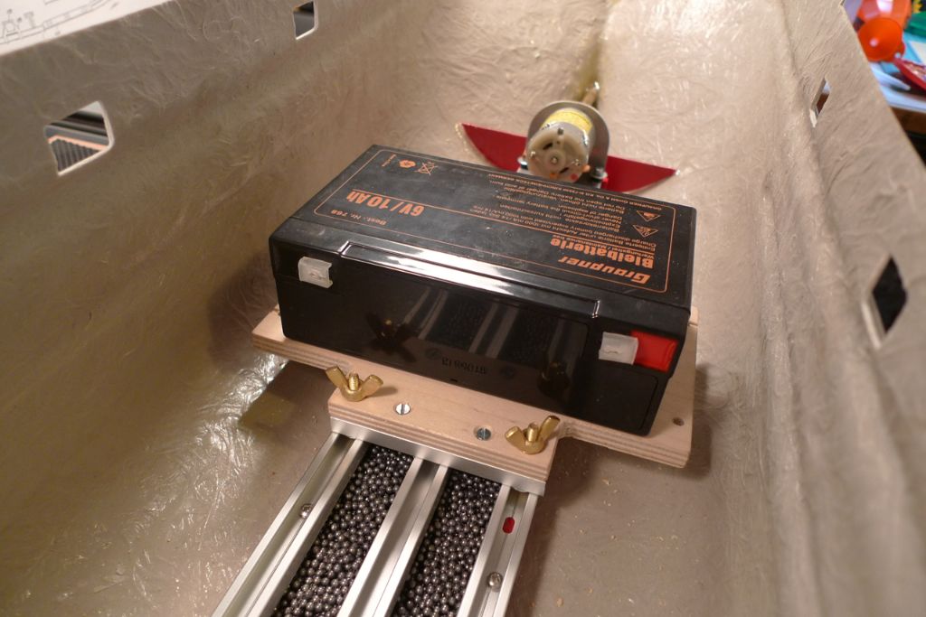
Already at this stage I had decided to make the battery moveable along the fore-and-aft axis, to provide a simple way of adjusting final trim. For this purpose, I now began building a battery sled from a piece of plywood, set on gliders of more curtain rod, and fixable against the fore-and-aft curtain rods with the help of some broadheaded brass bolts and wingnuts. The heads of the bolts fit nicely under the turned-in edges of the lower curtain rods.
First, though, a load of lead shot (bought in bulk from a diving equipment shop) was poured into the bottom frame and secured in place by pouring on epoxy resin.
The sled furthermore does the job of getting the battery a few centimeters up from the keelsoon, to mitigate against the risk of smaller quantities of water getting into the hull (e.g. via the propeller shaft), while still keeping this fairly large weight below the waterline.
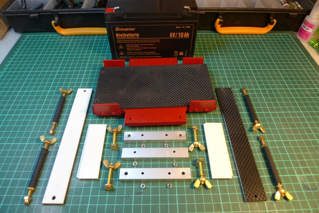
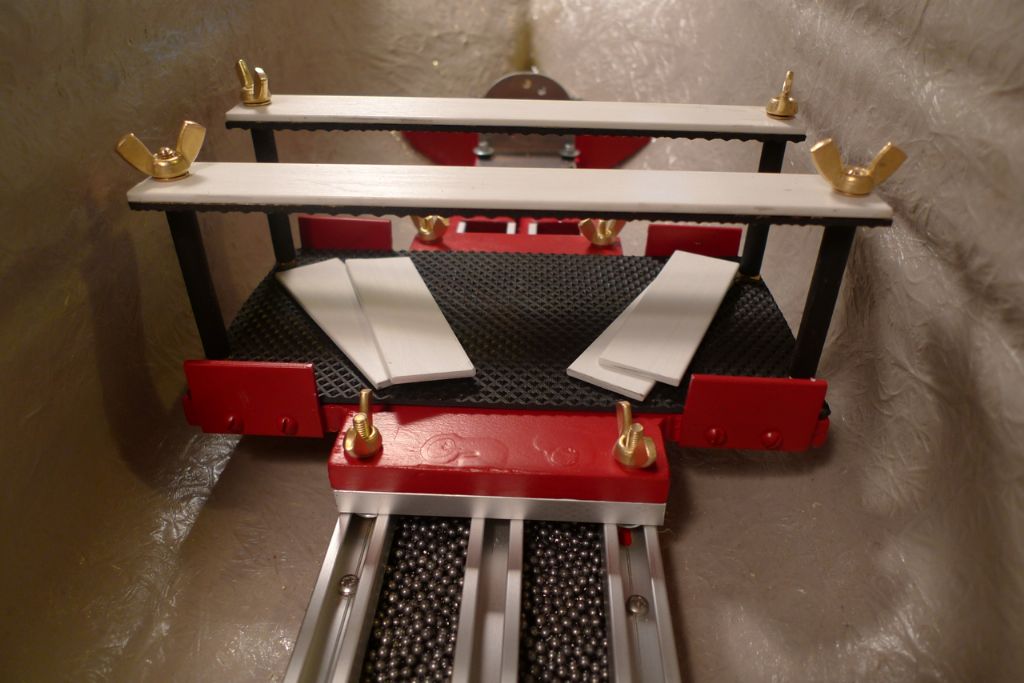
When finsihed the battery sled included the below component parts, by which it is possible not only to fix the sled to the boat but also the battery to the sled. The whole thing was designed to sit smack dab on the center line, but just in case, the short white glass fibre strips will function as shims, and by moving one or two from port to starboard or vice versa the battery can be adjusted sideways by 2,5 or 5 mm respectively. If even finer adjustment turns out to be needed, it will of course be possible to replace some or all of them with thinner shims.
To be continued …
/Mattias
Edited By Banjoman on 28/10/2014 14:10:42
Edited By Banjoman on 28/10/2014 14:11:20
29 October 2014 at 12:01 #53136Banjoman
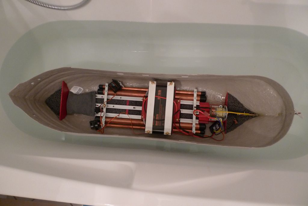
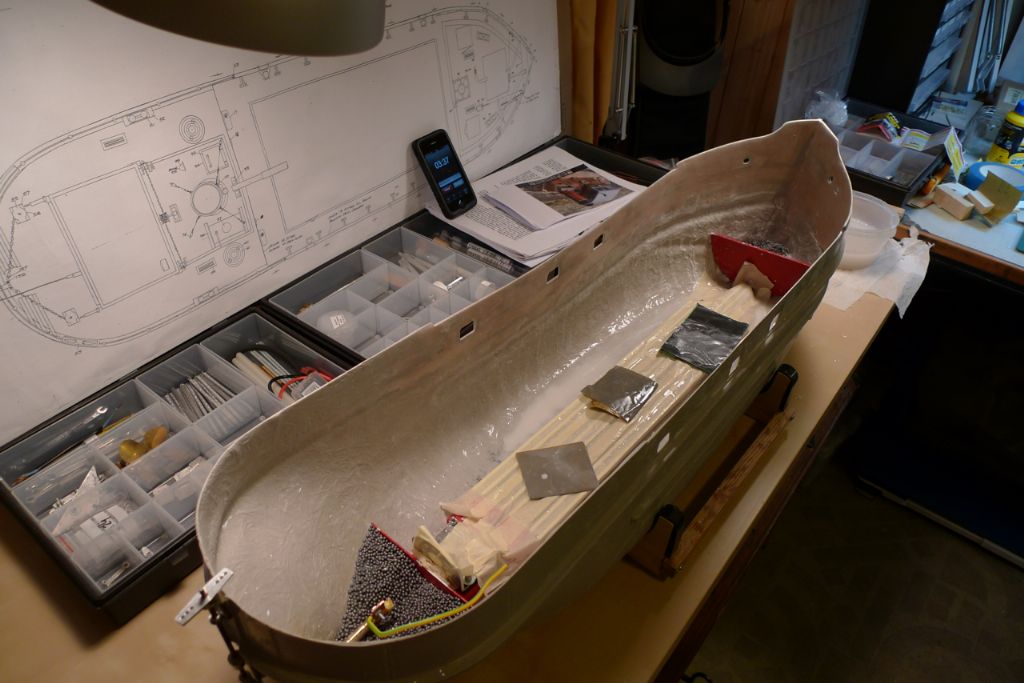
Participant@banjomanOnce the battery sled was finished and installed, I went on to put in most of the additional ballast. Some more lead shot was added in the forepeak, kept in place by a bulkhead similar to the one in the stern, but the main part was added by filling a few lenghts of left-over copper tubing with even more lead shot. This created a series of sealed-off containers (with the container also contributing to the total weight) that would fit neatly at the bottom of the central part of the hull (thus lowering the CoG as far as possible), would be removable if needed but when installed could be easily and solidly fixed to the curtain rod rails previously mentioned.
In the picture there is also a loose 1 kg sack of lead shot just aft of the fore bulkhead (while the box of white metal fittings has taken out for the photo) but this will probably not be (fully) needed in the end, given the weight of the various building materials used to construct the top side structures.
The observant observer will also notice a MTronik 15A ESC next to, and a band of copper around the back end of the motor. I found that my soldering iron would not heat up enough to provide secure solder joints on the motor can for the RF-suppressing capacitors, and I therefore instead clamped the capacitor legs against the can with a strip of sheet copper. This clamp also holds the green-and-yellow wire that connects to a similar clamp against the propeller shaft tube, thus earthing (or should that be watering?
 ) the can into water. II checked with a multimeter and there is indeed a connexion between the can itself and the outside tip of the shaft tube, which therefore will be left unpainted.
Finally, the rudder servo were not yet in its final and proper place as seen here (duh!), but only included as part of a general radio set-up test …

To be continued …
/Mattias
Edited By Banjoman on 29/10/2014 12:04:09
29 October 2014 at 18:26 #53146mike farrell
Participant@mikefarrell21522Hi Mattias ,What a nice build you have taken on .Some neat ideas which I am sure will be picked up and use by builders on the forum
Like your sled idea,will keep in mind for the future .Keep your build coming
 Michael30 October 2014 at 08:32 #53161
Banjoman
Participant@banjomanThank you very much, Mike, for your kind words!
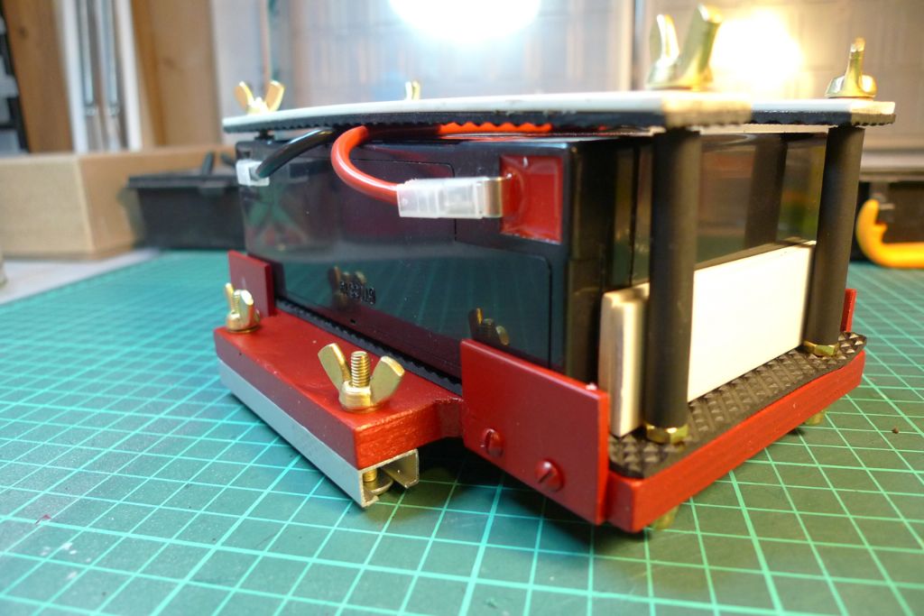
Here are a couple of more detailed photos of the battery sled as I made it.
Obviously the principle of a movable battery (which is the key idea here, as it allows one to use the fairly substantial weight of the battery for adjusting the trim) could be equally well achieved with a less elaborate construction, but I rather enjoyed going a little bit overboard (in the figurative sense only, of course) on this one …

The rubber sleeves on the upright bolts, by the way, are the outer sleeve material from a length of microphone cable (as a musician, I prefer making my own microphone and instrument cables from bulk cable and connectors, because that way one gets three or four times the quality for a given cost per metre of finished cable; I thus often have 40 or 50 metres of bulk cable around the house anyway…)
/Mattias
Edited By Banjoman on 30/10/2014 08:33:32
31 October 2014 at 09:17 #53192Banjoman
Participant@banjomanWith most of innards sorted out, time had come to put a lid on things, i.e. to install the decks!
The kit instructions give good and detailed guidance to how the main deck support frame should be constructed and installed. However, before actually putting the frame together I decided to check that the suggested width of 23 cm would be suitable. To this purpose I cut off three 23 cm lengths of square dowel and put these between the midship bulwarks.
At 23 cm, I found that the sides of the hull tended to be pushed out just a tad too much, and I thus cut down the three lengths dowel to 22 cm, which to my eye looked much better.
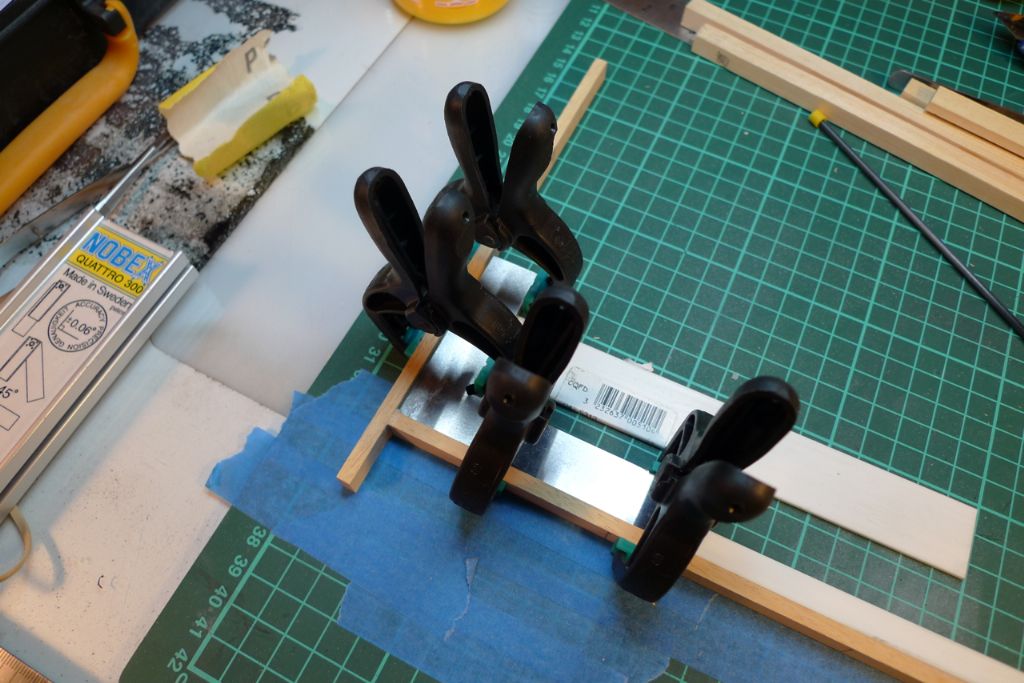
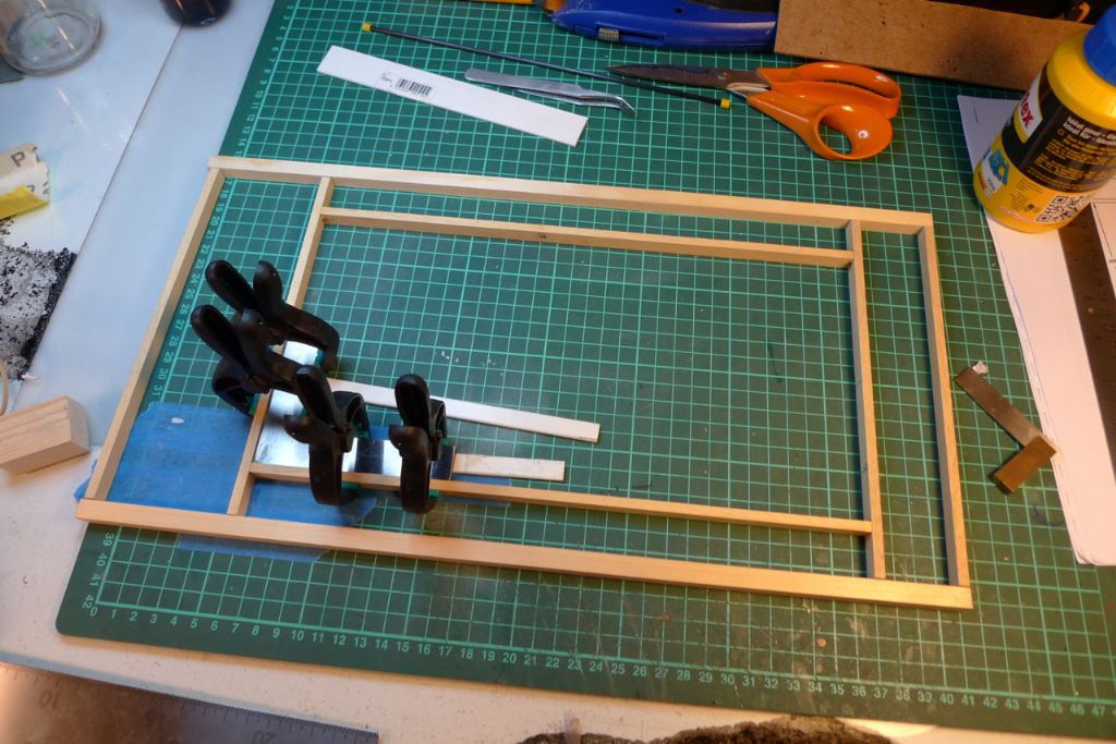
With the key measurements verified, it was time to start gluing the framework together, using a trysquare to keep things at right angles …
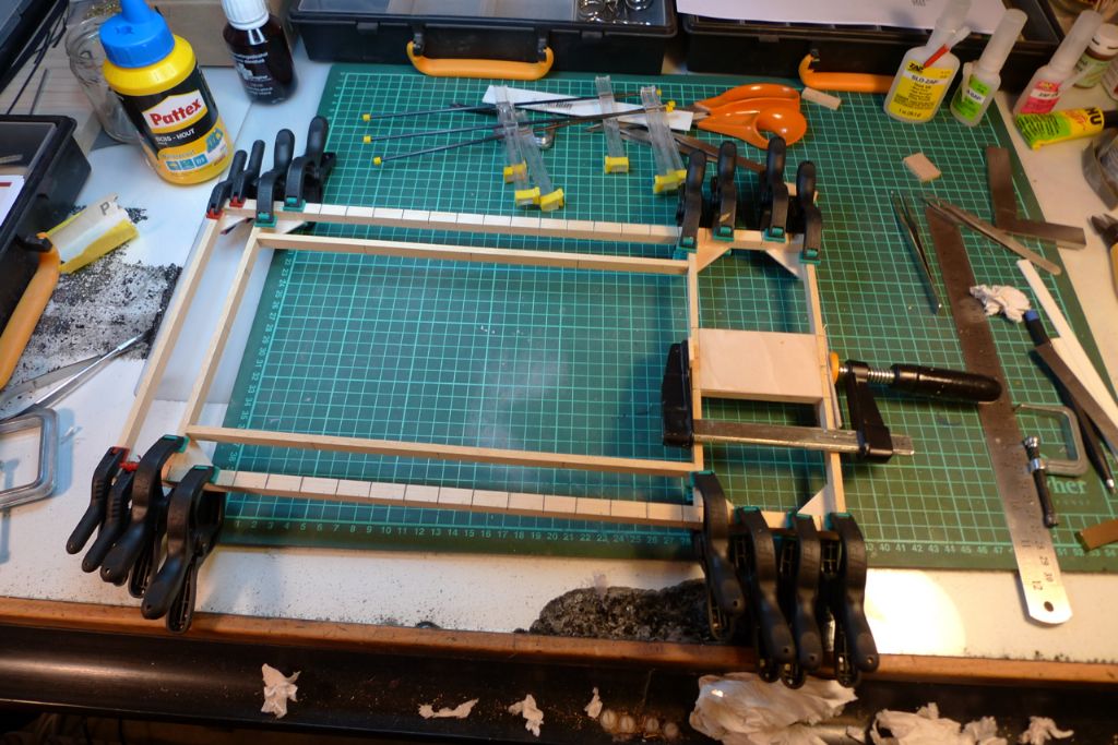
The basic frame, including the opening to go under the cargo hatch, was then reinforced at the corners, while forwards of the hatch a piece of 10 mm plywood was glued in to strengthen the bit where the mast will eventually pass through the deck.
As instructed, the outer lengthwise stringers were cut halfway through, to allow them to follow the bulwark sheer when installed while keeping the hatch frame square.
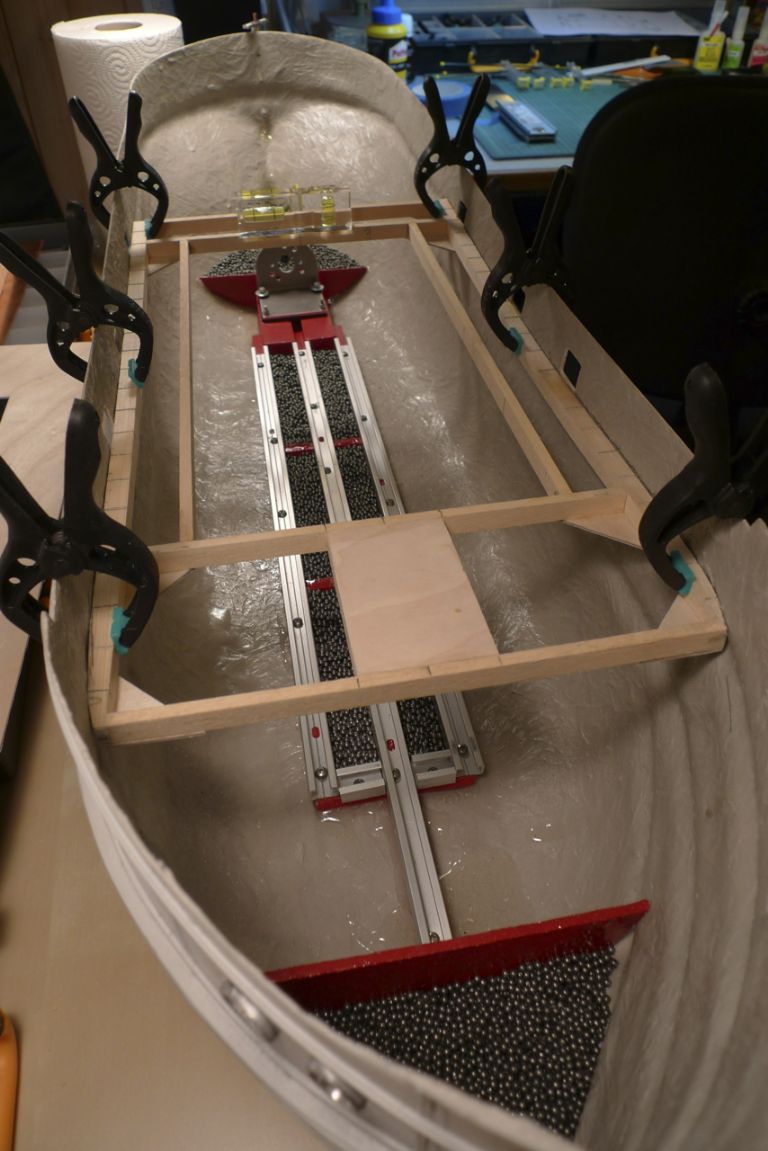
The first dryfit showed that this would work nicely, but made apparent two (minor) issues.
Firstly, I had at an early stage decided to cut out openings for the scuppers. Not because I intended to make the freeing ports work, which I didn't and haven't done, but because I think that if there is a freeing port visible on the outside of the hull, it looks rather nice to see a corresponding opening in the bulwarks behind it when looking from the inside. So far, so good. However, it turned out that I'd made a schoolboy error when measuring for cutting out those openings from the rubbing strakes below them, as it now became apparent that the hull was not all that symmetrical, with the port rubbing strake some 5 mm higher than the corresponding one on the starboard side! This would thus have be sorted out, but more about that later.
Secondly, the dryfit showed that the deck support frame would sit partly on, partly just above the indent in the hull made by the moulding of said rubbing strake.
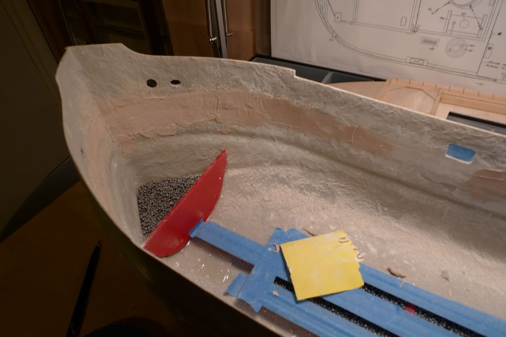
In other words, I realised that it would be better to put filler into this indent in order to get a full and solid joint between the frame and the hull, and I therefore decided to to all the smoothing out of the bulwark insides at this stage, rather than after installing the decks as suggested by the instructions.
Out came thus the Isopon P38 and the wet-and-dry papers …
The one job involved in modelling that I've always had the most trouble doing properly must surely be sanding, so for the final stage of smoothing the bulwark insides, I divided the job into four sectors (port midships, port bows, starboard bows and starboard midships), and went over each sector with in succession 1200, 1500 and 2000 grit wet paper, setting a five minute timer on my phone for each sector and each paper. It was a rather dull hour, but an hour well spent …
To be continued …
/Mattias
Edited By Banjoman on 31/10/2014 09:17:55
Edited By Banjoman on 31/10/2014 09:20:08
Edited By Banjoman on 31/10/2014 09:21:04
Edited By Banjoman on 31/10/2014 09:22:14
31 October 2014 at 14:54 #53203IAN_I
Participant@ian_iHi Mattias..
Great looking build, the work in progress is showing some very detailed design.
Look forward to seeing more pics.
Ian
1 November 2014 at 06:25 #53226Dave_P
Participant@dave_pI agree, I am enjoying your approach to problems and the ideas you are presenting. As Mike has said I am sure us model builders will gather ideas from your project for future reference as I have.
Cheers
Dave
Edited By Dave_P on 01/11/2014 06:27:46
2 November 2014 at 20:57 #53295Banjoman
Participant@banjomanThank you ever so much, Ian and Dave, for your kind words!
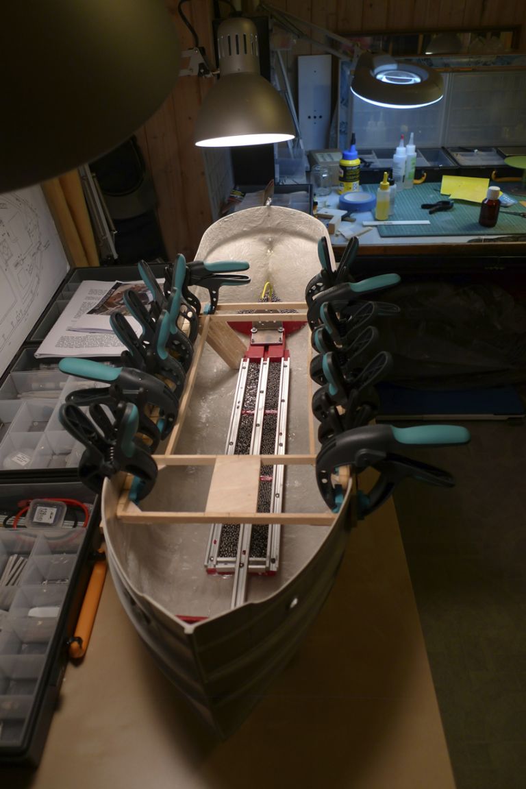
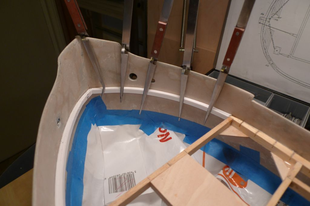
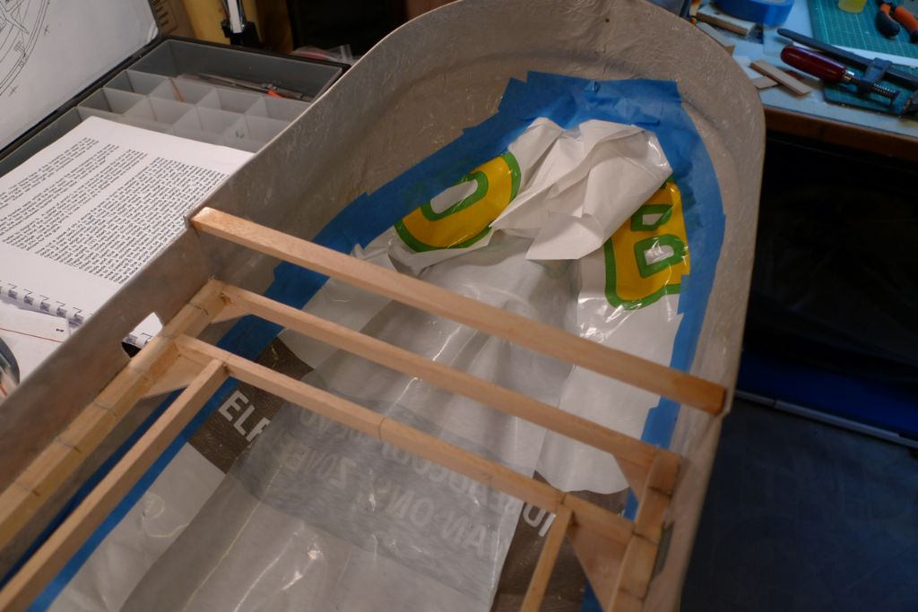
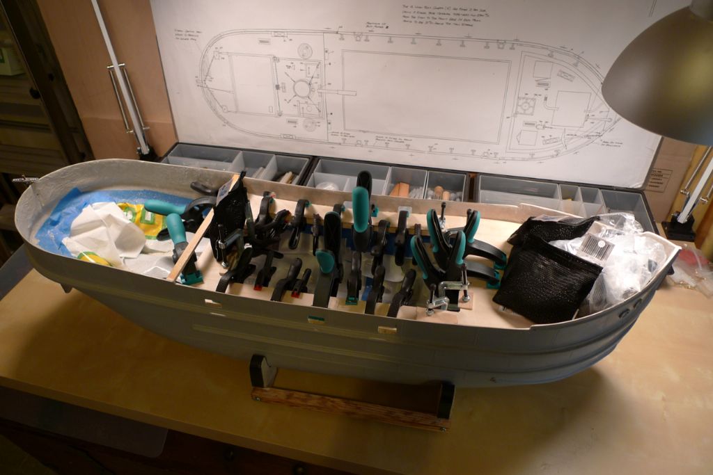
Well, with the inside of the bulwarks finally as smooth as I could wish for, it was time to glue the main deck support framework in place using 24 hour epoxy …
… followed by two layers of styrene strip at the bows; the first layer glued to the hull with epoxy, and the second to the first with Tamiya liquid cement.
The upper support for the quarterdeck bulkhead was also glued in place using 24 hour epoxy; the instructions suggested further securing this with the help of a couple of wood screws through the hull, but I found the glue joint on its own quite strong enough for the purpose.
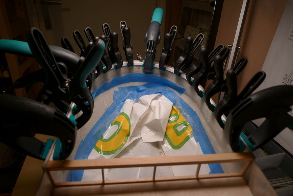
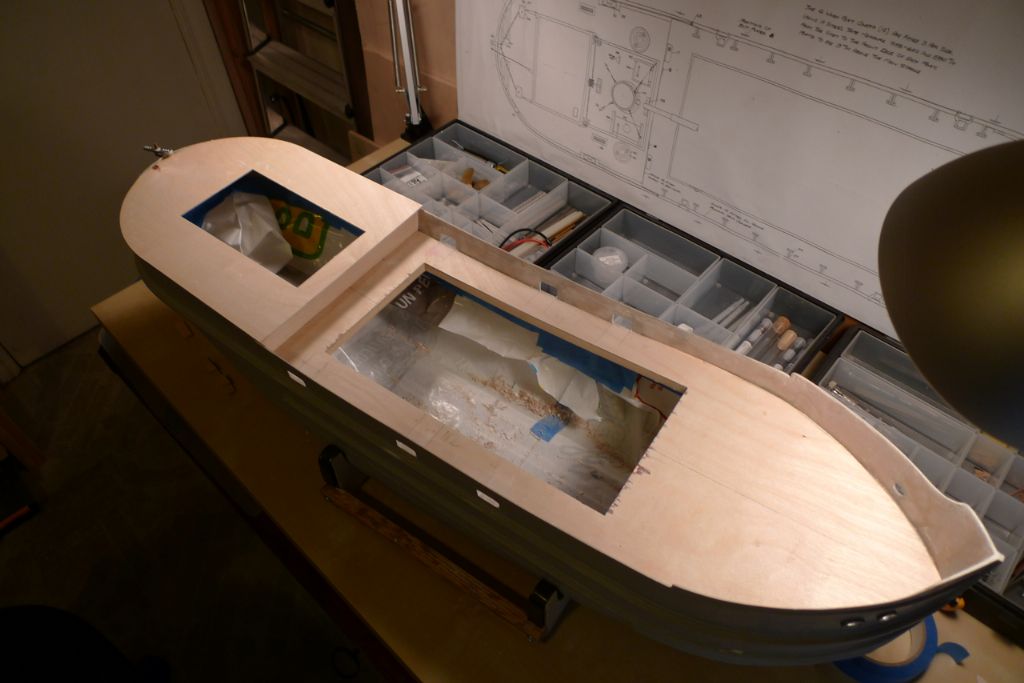
As the above pictures show, I also cut up a plastic shopping bag and taped it down into the bottom of the hull, in order to catch any sanding dust, spilled glue or other loose or sticky stuff that I would not want to have the trouble of removing afterwards and which might likely be produced by the next few build steps.
With the previous joints fully cured, the main deck could be glued in place …
To be continued …
/Mattias
Edited By Banjoman on 02/11/2014 21:22:48
3 November 2014 at 11:58 #53308Banjoman
Participant@banjomanWith the main deck in place, it was time to start correcting the miscut scupper openings in the bulwarks; initially by raising their lower edges with Isopon P38 filler to make them flush with the main deck.
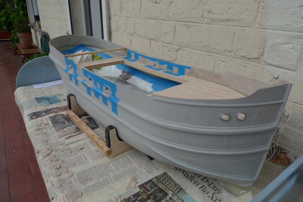
This build saw my first ever use of the oft-quoted (not least in Model Boats build articles) Isopon P38 filler, and I quickly found out that (a) it is an excellent filler, and (b) it doesn't half pong! In fact, the odour turned out to be so penetratring and strong that the first session of adding filler to the inside of the bulwarks led to a dispersal from my groundfloor workshop all the way up through the stairwell to the upper floors of the block of flats where we live!
Keen that I am to keep neighbourly relations on a continued friendly footing, I immediately vowed to take any further Isopon application work outdoors, and therefore at this stage of the build regularly brought the hull up to the flat and out onto our back terrace, where the potting table came in handy.
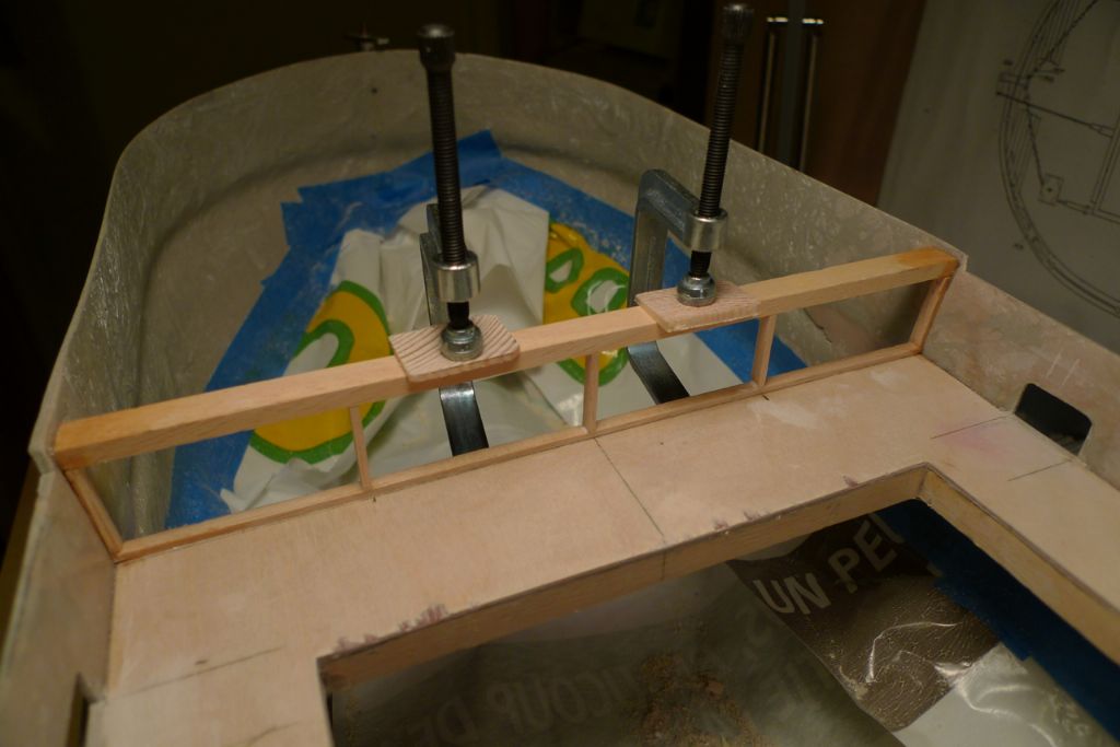
With the Isopon filler in the scuppers sanded down, both on the outside of the hull and flush with the main deck level in the openings, the next small job was to add the necessary stringers to make up the backing framework for the quarterdeck bulkhead …
… after which styrene support strips for the quarterdeck were glued in in the same way as the foredeck supports in the bows.
The quarterdeck plywood blank could now be fitted, first by measuring and cutting out the opening to go under the engine room superstructure …
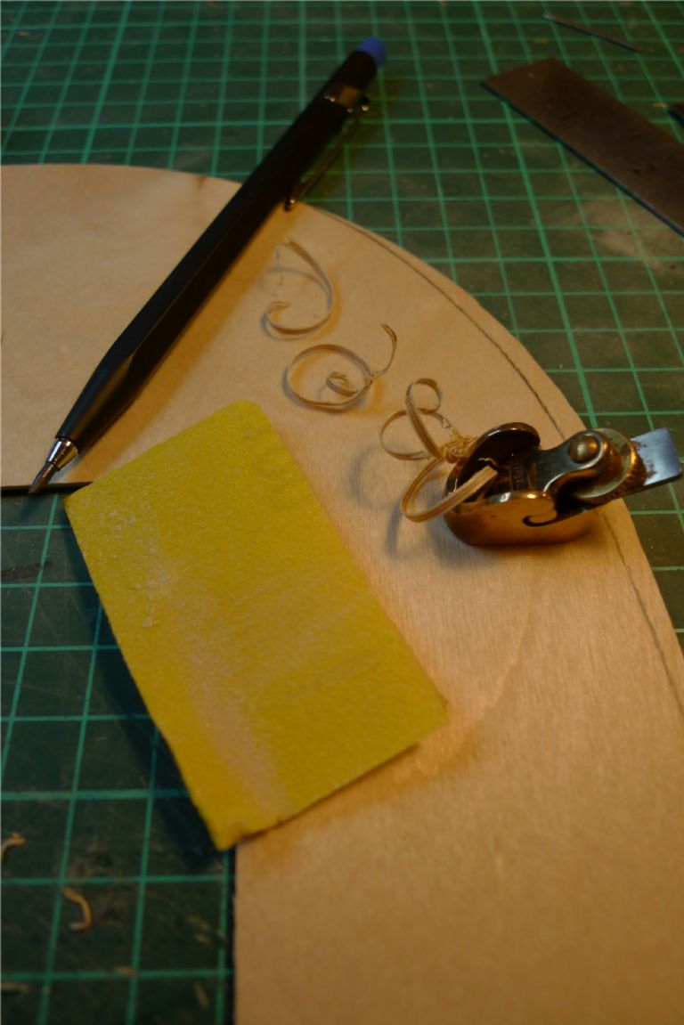
… and then by shaping the outside edges with the aid of a luthier's plane and some sandpaper.
To be continued …
/Mattias
Edited By Banjoman on 03/11/2014 12:01:29
3 November 2014 at 13:58 #53310IAN_I
Participant@ian_iHi Mattias…
Great work and lots of detail, thanks for the upload of pictures it says so much about the way we work and struggle with the changing seasons.
I also suffer with timing for the use of filler and spray painting, it would be great to leave the model outside to air and dry off…
The build is coming along …looking good.
Regards,
Ian
3 November 2014 at 14:05 #53311Banjoman
Participant@banjomanHello Ian,
Thank you ever so much for your kind comments!
What you say is very true indeed, and I was quite lucky in that the stage of the build where I was working with Isopon (or should that perhaps be "Isopong"?!
 ) just happened to occur in late August/early September last year, when the weather was on the whole quite nice, dry and warm, making those outdoors sessions not only feasible but agreeable too. No planning or foresight on my part, thus, but just dumb luck.
/Mattias
4 November 2014 at 10:07 #53337Banjoman
Participant@banjomanBefore the quarterdeck could be glued down, the rudder servo installation had to be sorted out.
Clyde Puffers typically had a completely external rudder construction, with an exposed short tiller at the top of the rudder post, linked to the steering wheel via a chain-and-pulley system.
This in turn means that any pushrod connection between servo and rudder has to be at least partially visible and needs to cross the after part of the quarterdeck, which again means that one either must install the rudder servo in line with the top of the rudder post or bend the pushrod to make it go below deck level somewhere under the engine room superstructure.
It seemed to me that the simplest and best connexion would be acheived by using a straight pushrod (well, pushrods, actually, as I'd already decided to go for a double rod system) in direct line, and a shelf of some kind therefore needed to be added in the engine room opening, more or less level with the quarterdeck, to make the servo arm stand just enough proud of the deck to make it level with the correspodning arm on the rudder post.
A further requirement for this shelf was to make it removable, to allow continued maximum access through the engine room opening to the motor and the propeller shaft, while the shelf also had to be strong enough to give a solid servo installation.
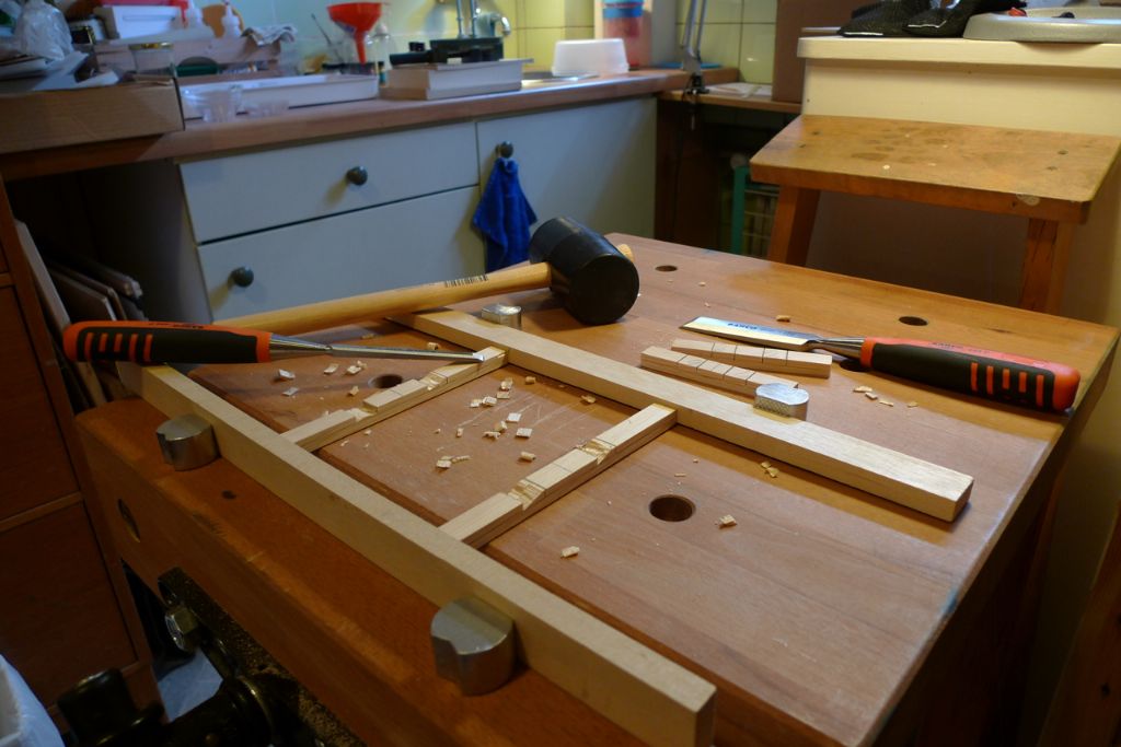
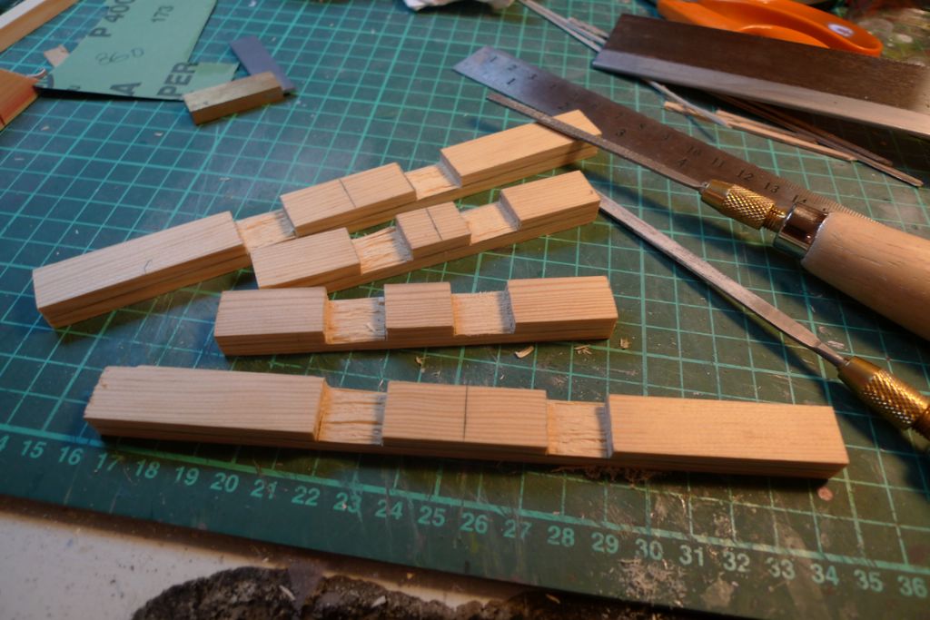
I therefore opted for a dovetailed frame made out of 10×15 mm spruce, and began its construction by measuring for and roughly cutting out the dovetail joints with a chisel …
… and then filing and sanding the rough-chiselled joints …
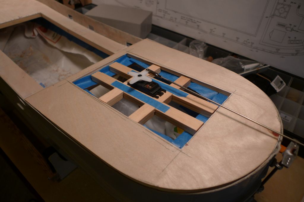
until they could be joined together, forming a level platform with a servo-sized hole in the middle. In the photo below, everything is just dryfitted, held together by tape, in order to check the approximate levels of the component parts and the pushrod connexion.
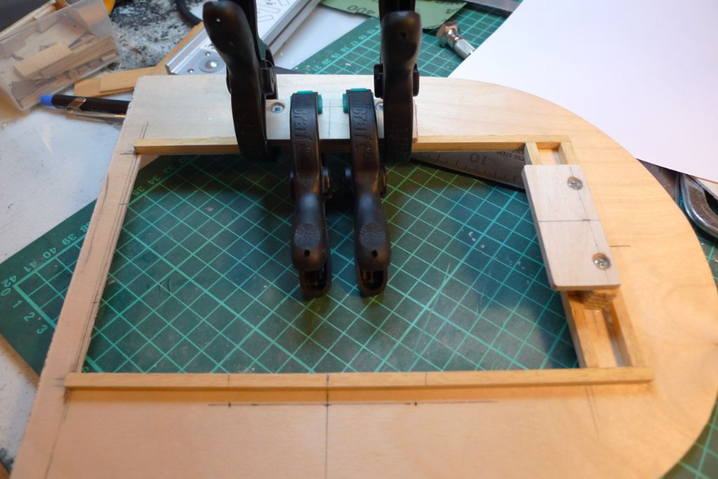
The engine room opening in the quarterdeck was then reinforced on the underside, and four ledges glued and screwed into place on which the servo shelf will rest.
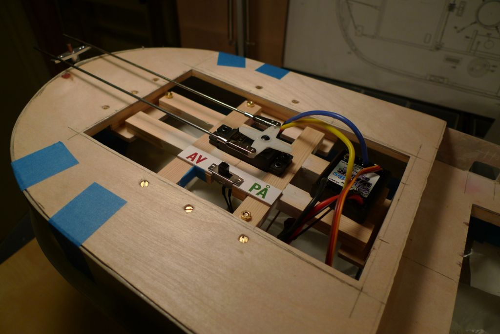
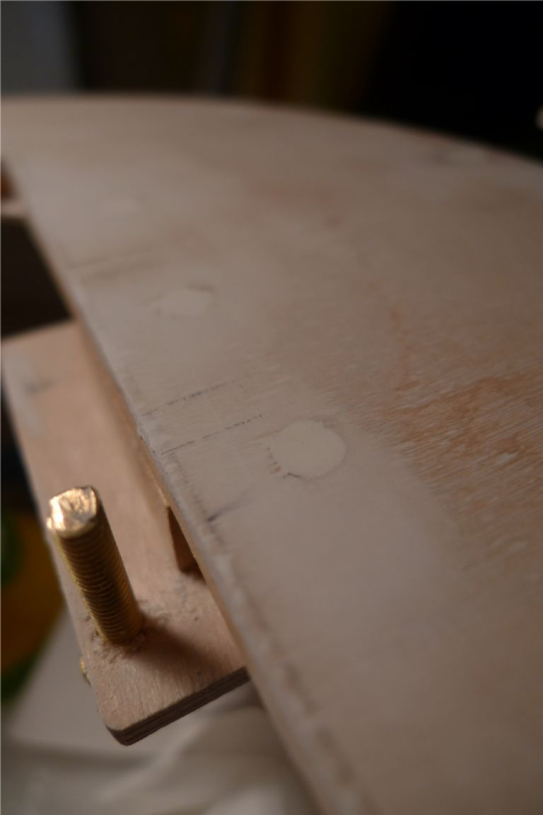
Three M4 brass bolts were added to stick up out of the ledges, and corresponding holes drilled through the arms of the servo shelf, making it possible to screw down the shelf to the ledges while keeping it removable if needed. There will also be room on the shelf for the ESC, a fuse holder and the necessary on/off switches, although at this stage only the BEC on/off was present. (And yes: "AV" and "PÅ" are the relevant words in Swedish; no prices will be given out for guessing from the picture which means "on" and which means "off " …
 )
)Anyway, as the below photo shows, I now had a nice, straight and pretty much perfectly parallell double pushrod system in place for the rudder.
With the rudder servo installation sorted, the quarterdeck was glued down with 24-hour epoxy and, once this had gone off, the joint was filled with Isopon …
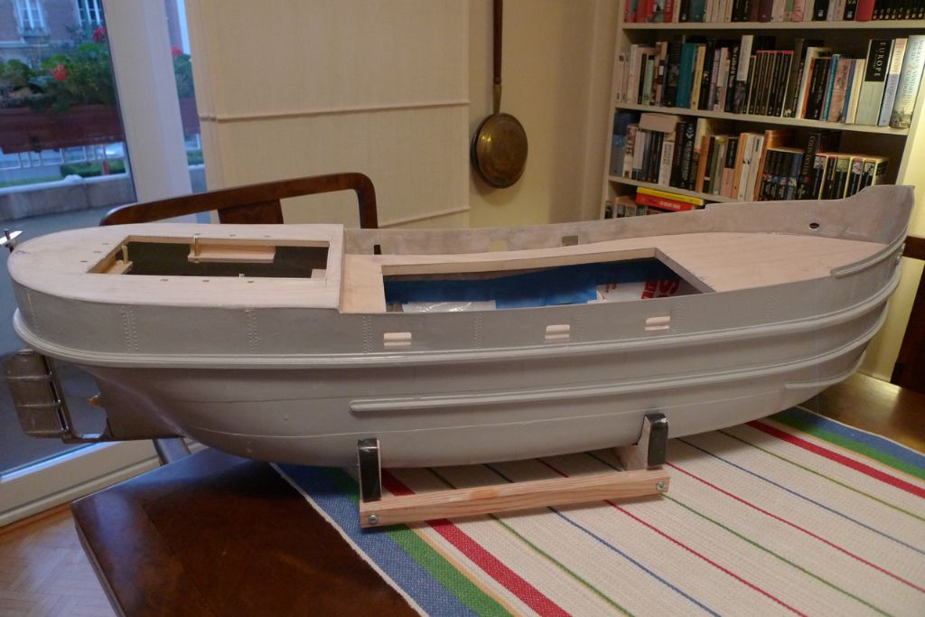
… and then sanded down to create the required flush hull/quarterdeck joint, after which the basic hull construction was more or less finished.
To be continued …
/Mattias
Edited By Banjoman on 04/11/2014 10:08:17
Edited By Banjoman on 04/11/2014 10:09:35
Edited By Banjoman on 04/11/2014 10:11:46
6 November 2014 at 09:40 #53391Banjoman
Participant@banjomanWith the main hull construction out of the way, I moved on to the bulwarks, starting by gluing the stempost into place …
… and also to the decks, which were first given a couple of layers of standard white filler in order to fill up the worst of the grain structure, to hide the countersunk screws in the quarterdeck and repair any saw tooth damage to the edges of the main hatch. After sanding this down, I added a couple of coats of dope-based sanding filler from Eskader in Stockholm (**LINK**). This procedure results in a nicely flat and smooth surface that, when painted, looks enough like it could be metal rather than wood underneath.
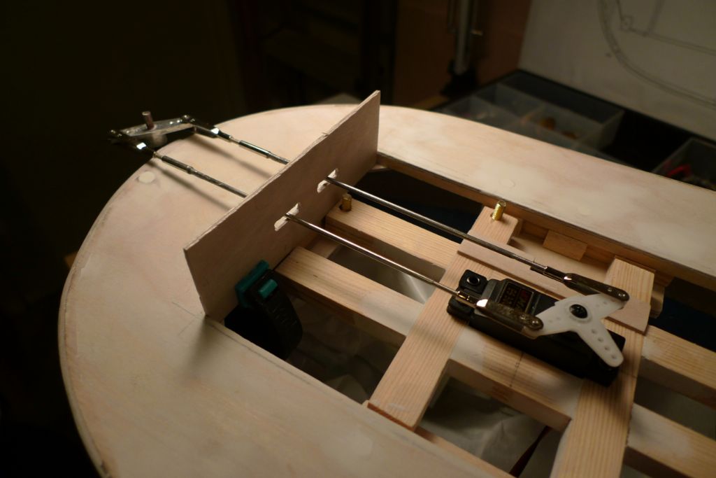
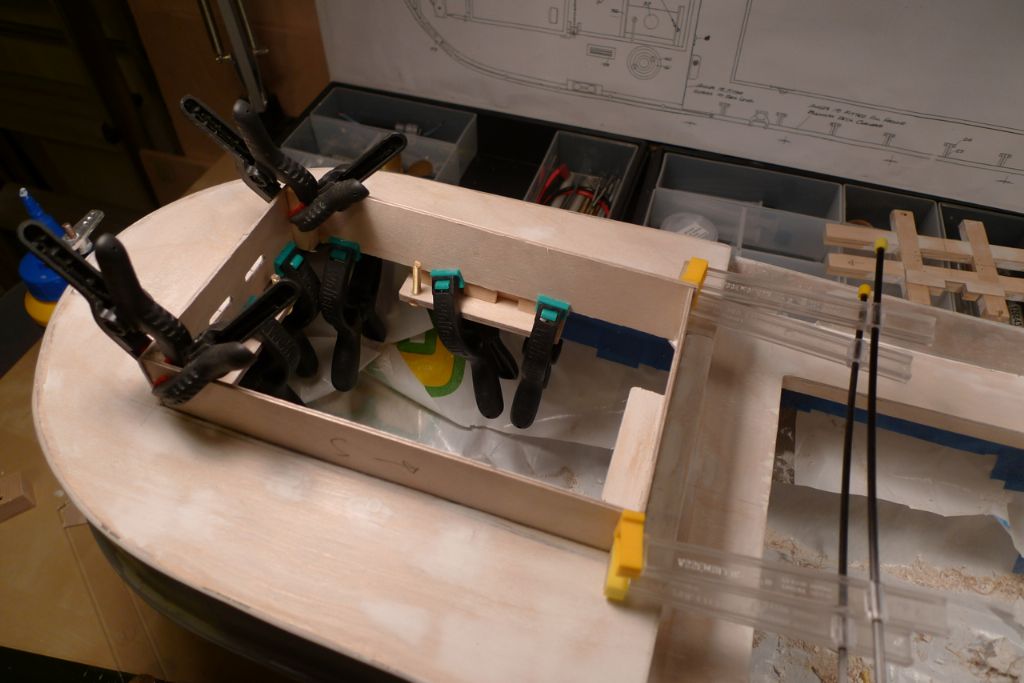
Next up was the coaming around the engine room opening, starting with the aftermost part in which a couple of slits had to be cut to allow the pushrods to pass through.
With these slits cut, and pushrod passage verified, the rest of the coaming was cut out from thin plywood and glued in place.
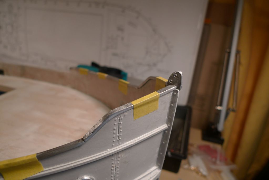
At this tage I also bent into shape and dryfitted the foredeck bulwark white metal railing caps. Unfortunately, it turned out that the furnished lengths of these fittings were not enough to fit the complete raised foredeck bulwarks. However, an e-mail to Mountfleet Models was met with an equally prompt and helpful reply, and not many days later a few more lenghts turned up in my mailbox. Although it would of course have been even better had a sufficient length been included from the start, it is nevertheless always a pleasure, I must say, to meet with that sort of exemplary customer service!
To be continued …
/Mattias
Edited By Banjoman on 06/11/2014 09:41:49
Edited By Banjoman on 06/11/2014 09:43:05
7 November 2014 at 09:35 #53443Banjoman
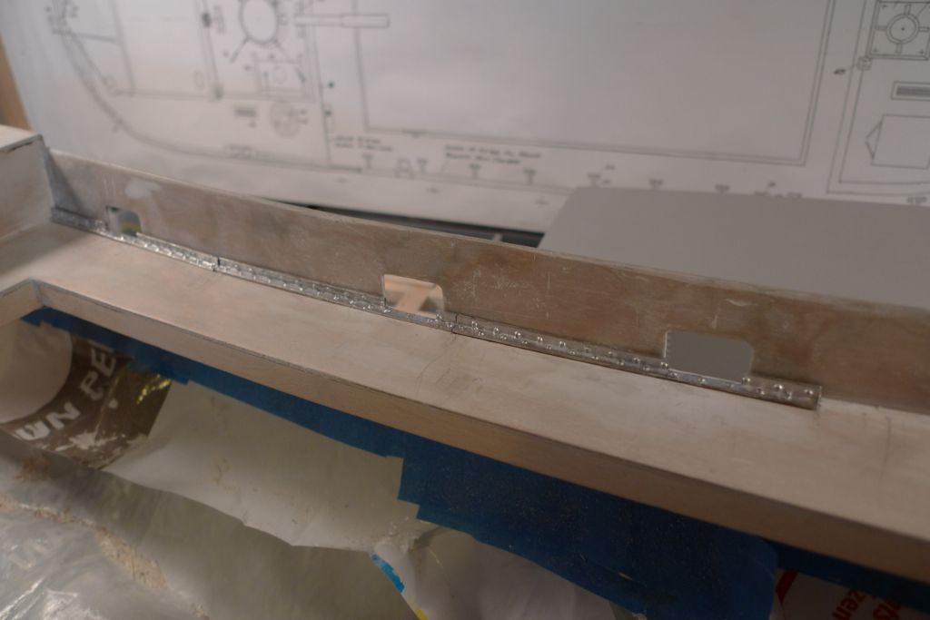
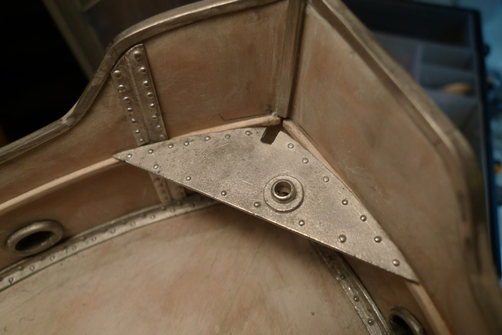
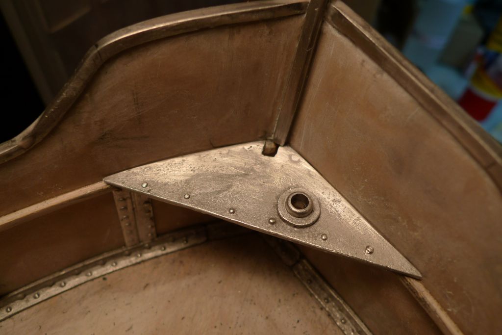
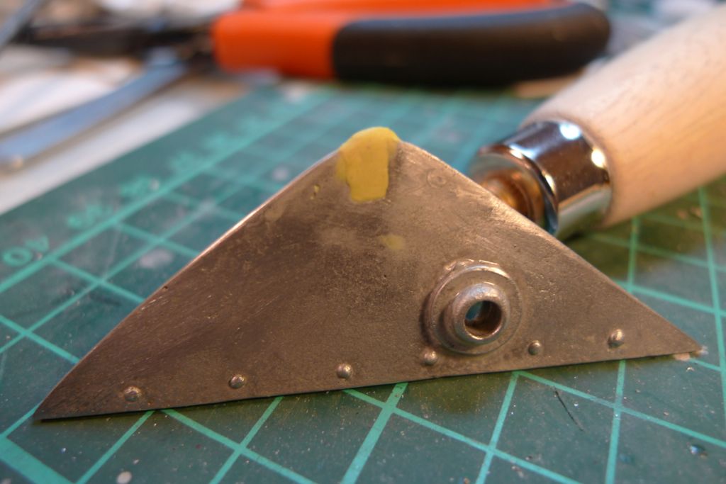
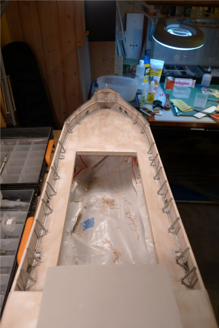
Participant@banjomanThe next set of white metal fittings to be dealt with were the deck/bulwark angle reinforcements …
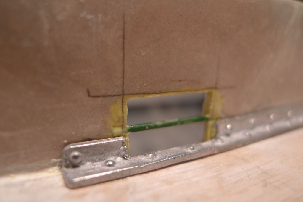
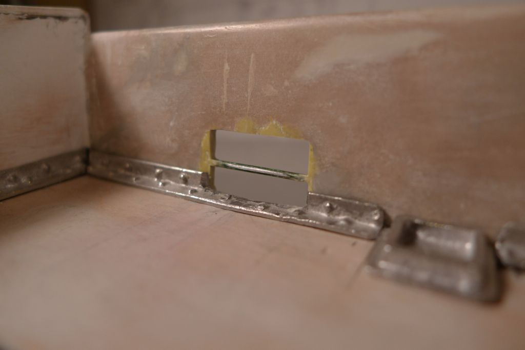
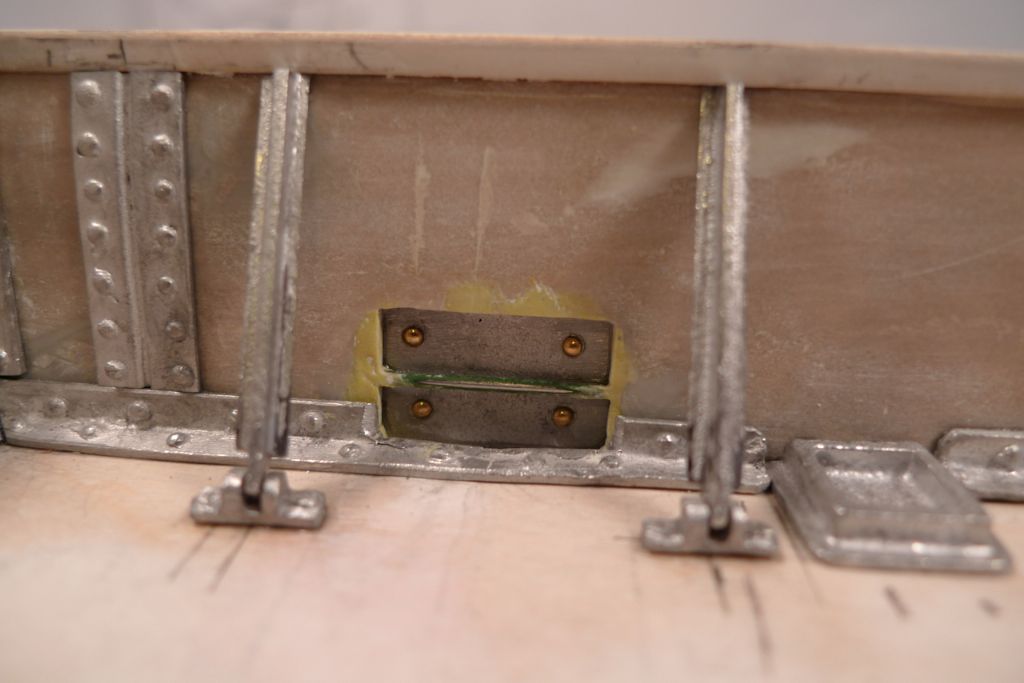
… which I modified slightly in the six locations where they crossed the freeing port openings. The latter were now also given their final size and shape, with the help of small amounts of Milliput added along the edges.
I likewise added crossbars to the openings, and filed and sanded the Milliput repairs around each opening to the desired appearance.
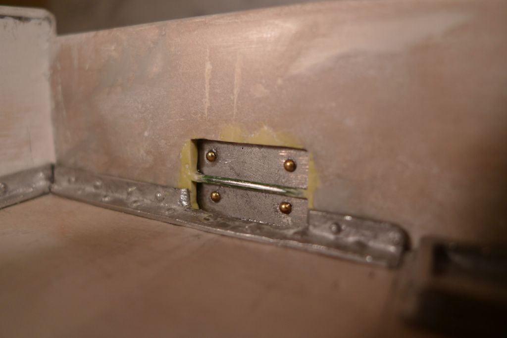
Finally, the freeing port covers where glued to the outside of the hull. These had already been given some additional detailing in the form of rounded brass nail heads glued in to correspond with the moulded hinge fastening rivets shown on then outside faces of the freeing port covers.
At this stage, the sampson post deck supports where also glued in place.
To be continued …
/Mattias
Edited By Banjoman on 07/11/2014 09:36:07
8 November 2014 at 22:07 #53499Banjoman
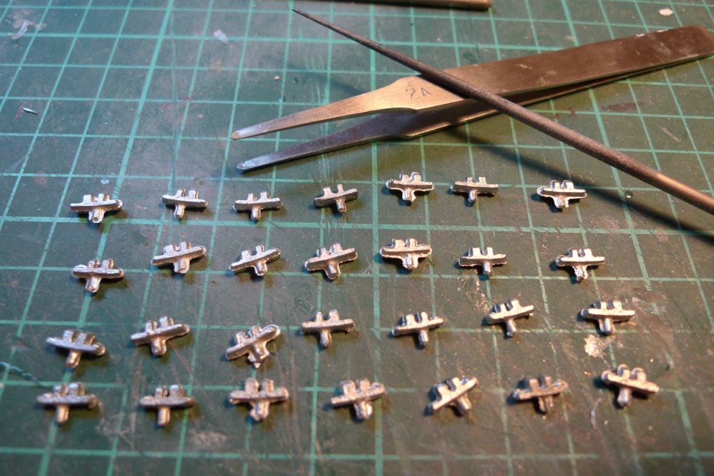
Participant@banjomanMost of the white metal parts furnished with the kit were of excellent quality, with crisp and detailed castings; some, however, were less so, and among these lessees where the inner bulwark strut deck supports, which meant time to break out the needle files and clean them up.
Intermittently with the filing (which did get a tad boring after the first few
 ) I also glued the first of the bow bulwark stringers in place …
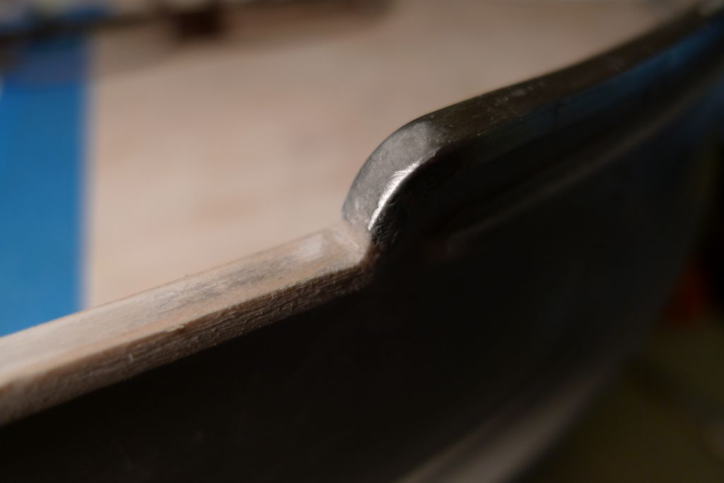
 … and also the bulwark cappings.
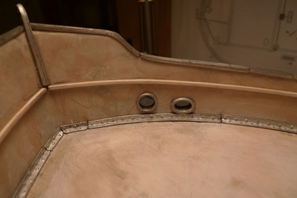
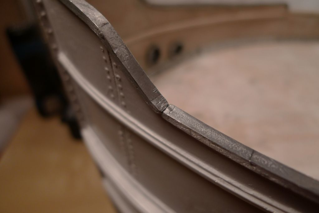
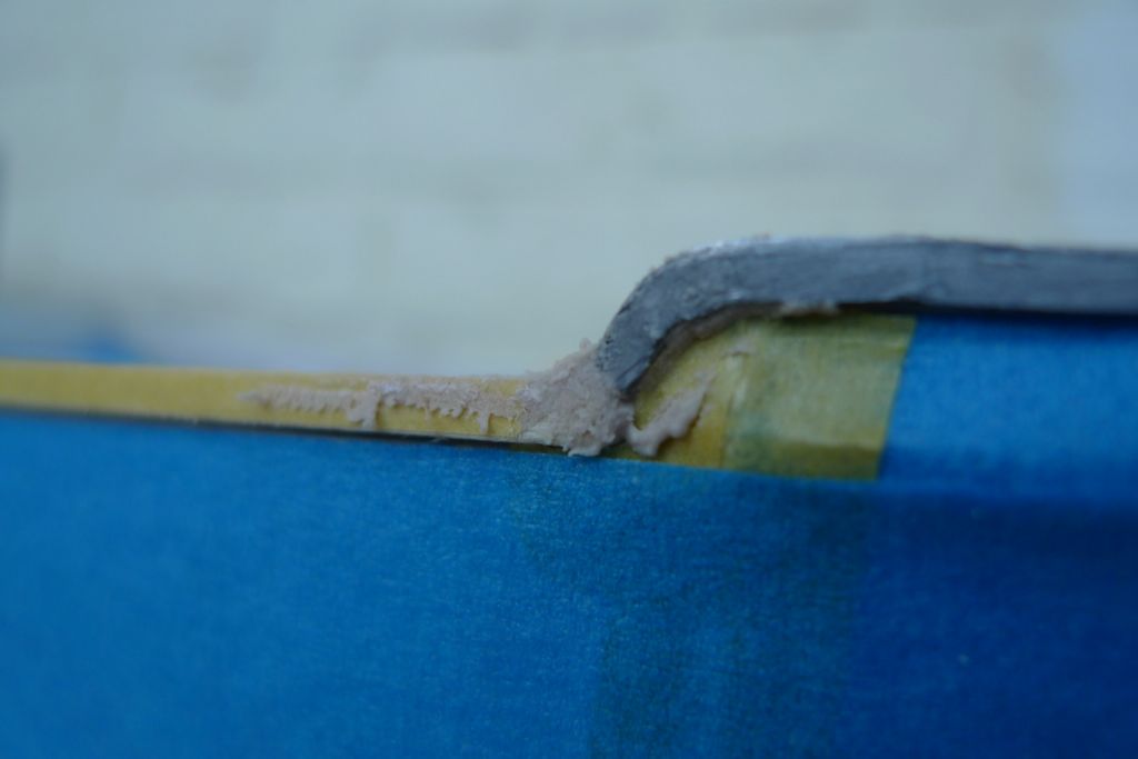
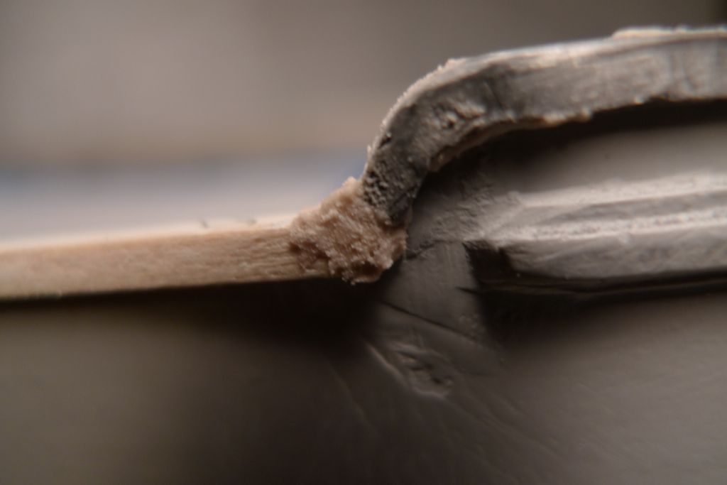
At the bow these are, as already mentioned, from white metal sections, whereas the main gunwale cappings along the mid deck were made up from a length of milled out wood strip. Where the bow cappings meet the mid section ones, Isopon filler had to be applied to the joint (and also to the joints between the individual white metal cappings). When applying this kind of filler, which goes off rather quickly and when fully hardened is hard indeed, I always take the trouble of masking off the area to be filled …
… in order to make sure that filler is only applied where it more or less needs to be …
… and thus save considerable on the ensuing sanding efforts. The wood cappings were of course treated with the usual standard filler plus Eskader sanding filler.
To be continued …
/Mattias
9 November 2014 at 16:18 #53509IAN_I
Participant@ian_iHi Mattias…
Your build is of quality and will look forward to the next instalment..
Best regards,
Ian
9 November 2014 at 18:49 #53514Amy jane September
Participant@amyjaneseptember49770Hello Mattias.
I thought It was about time I popped in to say I've been enjoying your build too! Nice detailing, I think the end result will be quite lovely
Amy jane
10 November 2014 at 08:54 #53524Banjoman
Participant@banjomanThank you very much, Ian and Amy jane!

At the next stage, I discovered something that I rather ought to have noticed before but hadn't, namely that the bows are not symmetrical between port and starboard!
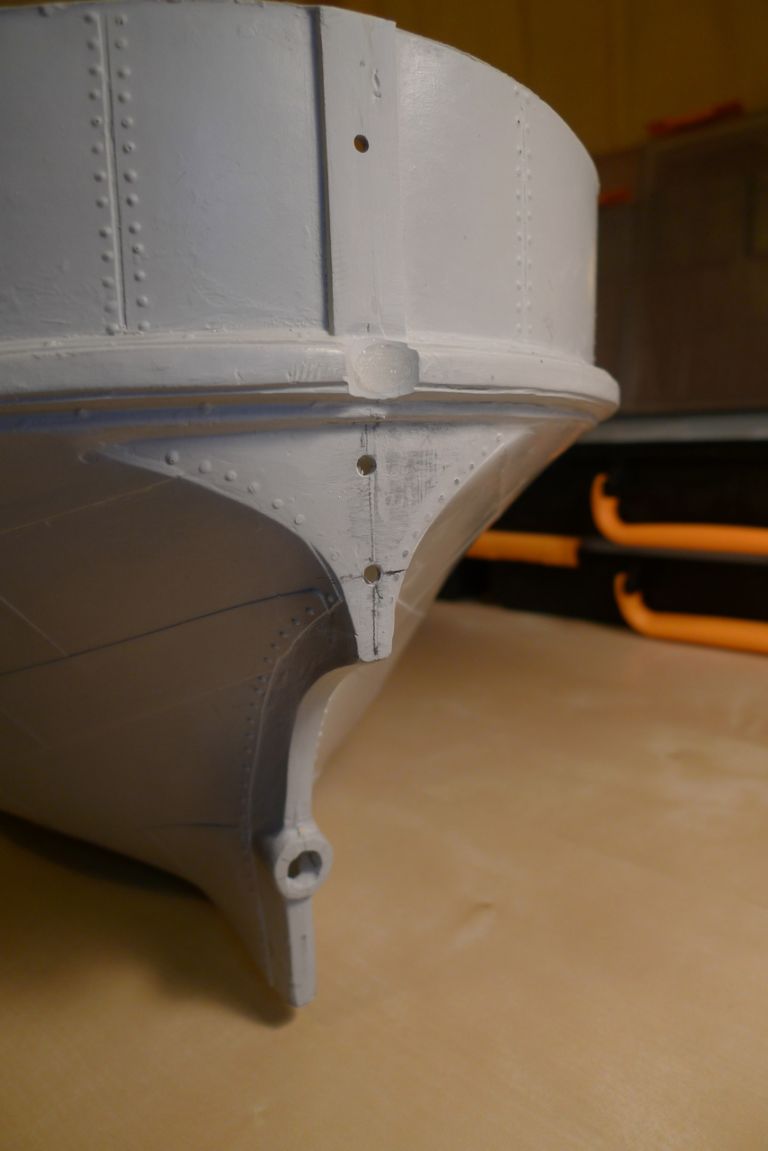
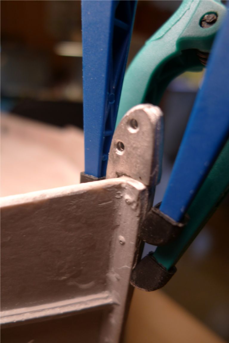
What gave the game away was trying to fit the lower bow plate and the rivet reinforcement straps at the bows … As the photo clearly shows, the raised foremost part of the bulwarks are about 5 mm longer to starboard than to port, and the bow plate soes not have the correct shape compared to the hull. Hmm …

If I had discovered this before fitting the bulwark cappings, the assymetry could have been fixed in a jiffy by cutting off the appropriate amount of bulwark top to starboard, but as it were I did not feel much like tearing it all up and risk rendering the cappings unusable, so I decided to stick it out and to try to acheive at least the illusion of symmetry by very careful placement of the component parts.
First job was to sand the bow plate down to fit snuggly into the bows. This of course also meant sanding down the raised rivet heads on the front of the plate, as they no longer were correctly positioned in relation to the plate edges (I'll come back to thsee rivets later on.)
The notch that was supposed to fit around the stem post was also out of kilter, and I therefore filled it in with Milliput.
The same operations were then carried out on the smaller top bow plate, and the bow plates dryfitted so that the rivet straps could be glued in in relation to these in such a way that at least part of the assymetry became camouflaged: the rivet straps to port and starboard have been aligned in relation to the outer corners of the lower bow plate and the downward curves on the bulwark cappings, which, unless one looks at it really carefully, gives an impression of a sort that things are more symmetrical than is really the case.
My pious hopes (vindicated at a later stage) were also that the general assymetry of the foredeck fittings and superstructures would further mask the lack of symmetry here.
At this stage I also roughly measured the white metal bulwark support struts to just over their required lengths.
The careful observer will note that one such strut (the fourth from the bows) is missing to port; this is because when marking out with an awl where to drill for the deck strut supports, I put a bit too much force behind the awl at that position, and pushed the point clean through the deck! This was easy enough to repair with a dollop of Milliput, which when the photo was taken was still in the process of setting.
The struts were then trimmed to a tight fit under the bulwark cappings, and glued in place using epoxy.
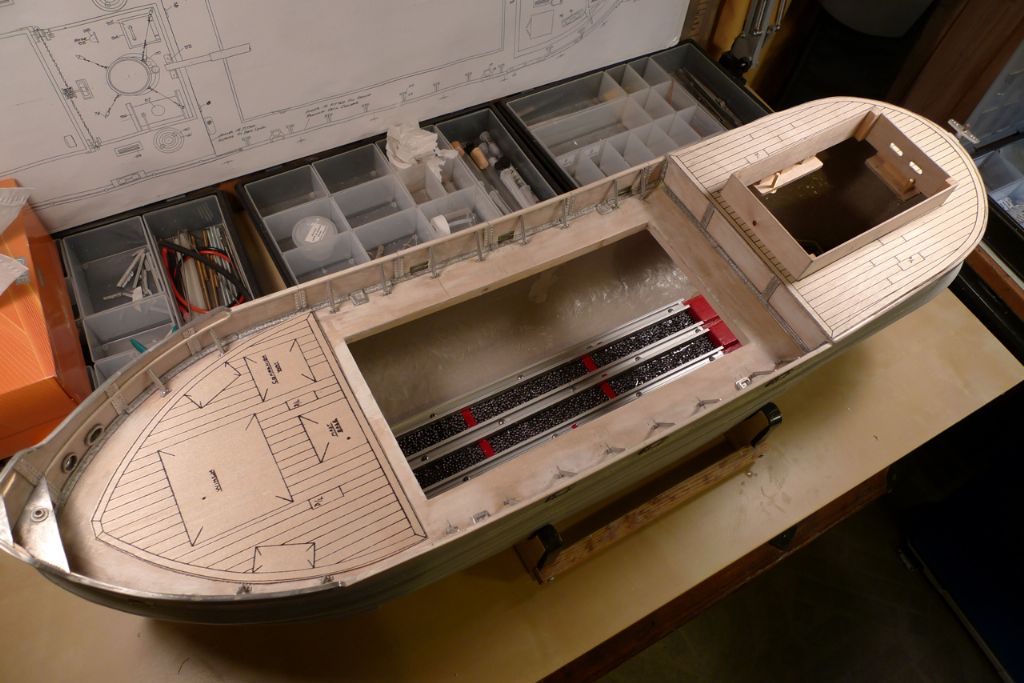
My abovementioned discovery of the assymetrical bows also made me fear the worst for the printed deck overlays, and I therefore cut these out from their sheet of plywood and dryfitted them. As the photo clearly shows, the quarterdeck overlay fitted reasonably well, and would have been usable, but the foredeck overlay really did not fit at all.
The fit would have been slightly better if I'd made the main deck support 23 cm wide as per the instructions instead of the 22 cm I went with based on what produced the in my view best hull shape midships. Still, though, even with 5 mm more on each side at the aft end of the foredeck, the overlay would not really have fitted properly.
This did not matter all that much, as I'd already considered replacing the printed overlays with individually laid deck planks. This dryfit tests thus clinched that matter for good, and I'll get back to the planking at a later stage of the build.
To be continued …
/Mattias
Edited By Banjoman on 10/11/2014 08:54:52
Edited By Banjoman on 10/11/2014 08:59:04
10 November 2014 at 15:06 #53532IAN_I
Participant@ian_iHi Mattias…
Great work, good to see the methods you use and work in progress.
Look forward to the next instalment…
Regards,
Ian
11 November 2014 at 09:09 #53548Banjoman
Participant@banjomanThanks Ian!
Well, here goes with that next instalment!
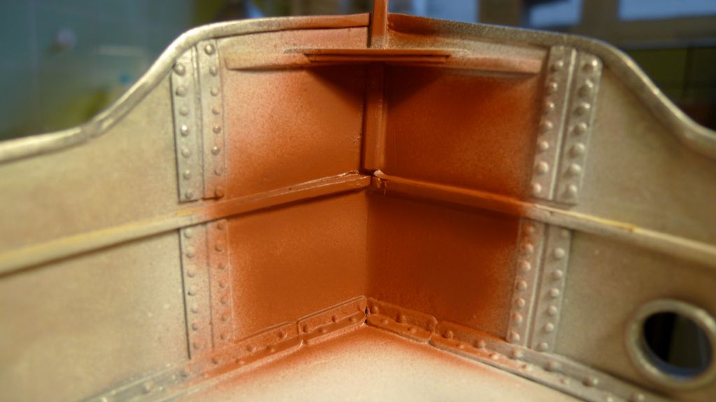
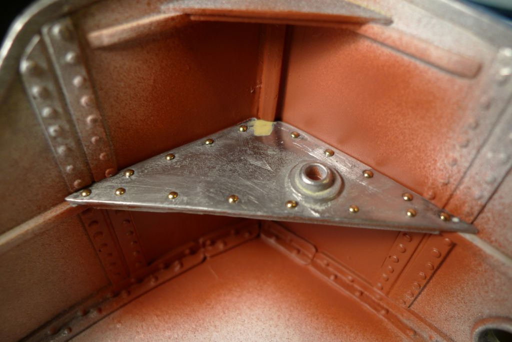
Painting the hull was now fast approaching, but before the main paint job begun, and before the last of the bulwark inside fittings were glued in place, I pre-painted certain areas that would become difficult to reach once the fittings were in place.
As mentioned earlier in the thread, I had decided from the start to try my hand at airbrush painting for the first time on this model, and while it is a marvelous tool in most respects, one of the things an airbrush really cannot do is paint around corners! With a gravity feed airbrush like the one I use, there is also the further limitation that you cannot tilt the airbrush further back than level with the horizon (and even that position should be avoided by a few degrees), as the paint will otherwise run backwards into the workings of the airbrush instead of being blown out through the nozzle.
As the lower bow plate would certainly create a paint shadow area that I would be unable to reach, I therefore painted the corner of the bows before gluing down the bow plate. To preserve an unpainted surface for the bow plate glue joint, the upper edge of the stringers was masked of with a thin strip of masking tape.
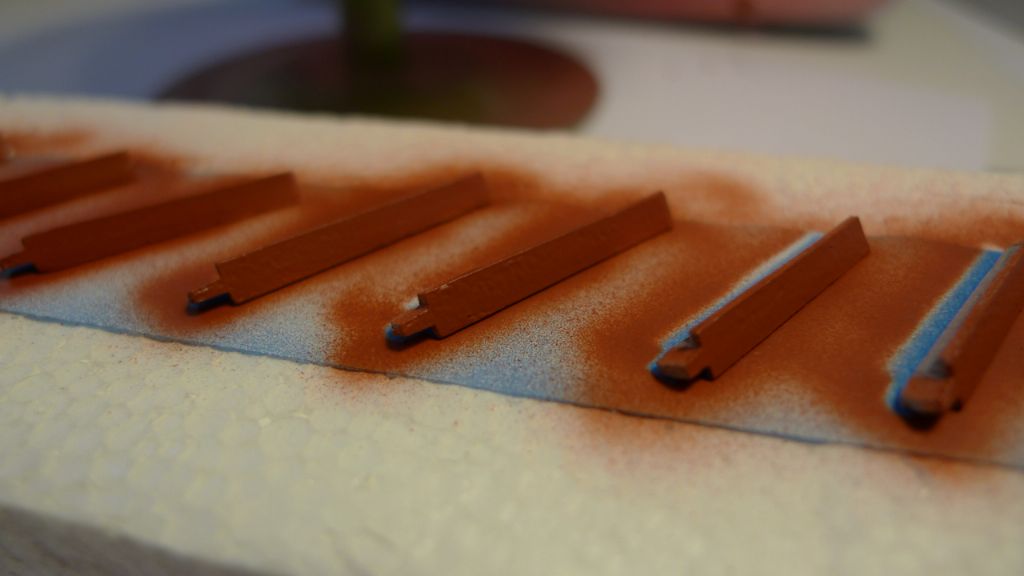
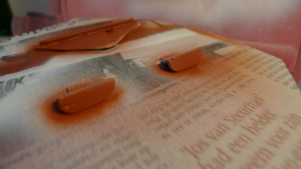
For similar reasons I also painted the back sides of the bulwark support struts before they were glued in place.
The same treatment was given to the underside of the bow plate (again with what would be the glue joint surface masked off) and to the undersides of the quarterdeck bulkhead step plates.
These parts were then glued in. Here is for instance the bow plate, and as the picture shows the molded rivet heads that I had had to sand down earlier were replaced by cut off brass nail dome heads. The joints between the plate and the bulwark were then filled with a small amount of Milliput (not shown in the photo) to get a completely smooth and joined-up fit.
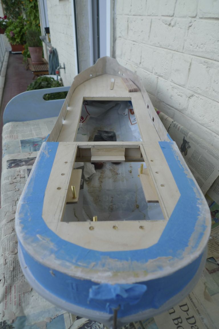
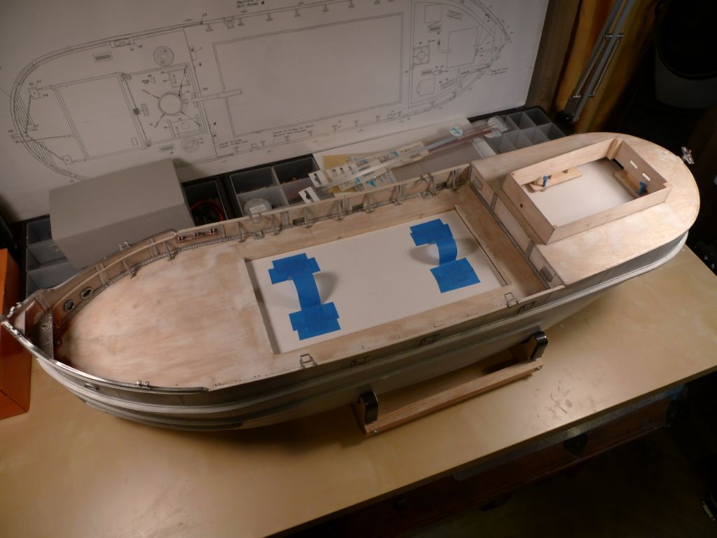
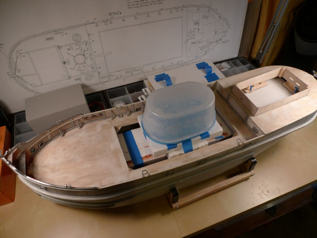
With everything in place and ready for the main painting event to start, I also masked off the interior. For the main hatch, a removable cover was fashioned from a piece of cardboard, while under the engine room opening another piece of cardboard was wedged in place against the servo holder ledges, and the remaining gaps filled with crumpled-up tissues.
Under the cardboard hatch cover, a bundle of cell foam block were taped down so that the the hull, when balanced upside down on a few more cell foam blocks plus a plastic container, would have no part of the bulwarks or engine room coamings touching the table.
Before painting (but after the above photos were taken) the edges of the main hatch were also masked off with masking tape in order to keep a paint free surface there for the later main hatch coaming glue joint.
To be contnued …
/Mattias
Edited By Banjoman on 11/11/2014 09:15:03
Edited By Banjoman on 11/11/2014 09:15:28
Edited By Banjoman on 11/11/2014 09:17:06
-
AuthorPosts
- Please log in to reply to this topic. Registering is free and easy using the links on the menu at the top of this page.
Code of conduct | Forum Help/FAQs
Latest Replies
Home › Forums › Building Kits › Topics
-
- Topic
- Voices
- Posts
- Last Post
-
-
Amati j class yacht kit
Started by:
 ashley needham
in: Buy/Sell or Trade
- 3
- 4
-
20 hours, 59 minutes ago
 Richard Simpson
-
North West Model Shipwrights Society
Started by:
Bob Wilson in: Club News
- 6
- 17
-
21 hours, 45 minutes ago
Bob Wilson
-
Tin Plate Clyde Puffer
1
2
…
6
7
Started by:
Len Morris 2 in: Scratch build
- 12
- 170
-
22 hours, 19 minutes ago
Len Morris 2
-
Wild Duck meets Eventide
Started by:
Tim Rowe in: Scratch build
- 5
- 22
-
2 days, 7 hours ago
 Tim Rowe 1
-
Todays Boating
1
2
…
199
200
Started by:
 ashley needham
in: All things floating
- 83
- 4,989
-
3 days, 2 hours ago
 ashley needham
-
New Website Forum – Discussion Topic
1
2
…
6
7
Started by:
 Colin Bishop
in: News and Feedback
- 20
- 172
-
3 days, 6 hours ago
 Chris Fellows
-
ballasting a paddle steamer
Started by:
 Alasdair Allan
in: All things floating
- 5
- 17
-
5 days, 5 hours ago
 Colin Bishop
-
Aerokits pt boat bulkhead plans wanted
Started by:
Roo Hawkins 1 in: All things floating
- 1
- 1
-
5 days, 6 hours ago
Roo Hawkins 1
-
The new journey begins
1
2
Started by:
mick east in: Build Blogs
- 6
- 28
-
5 days, 11 hours ago
mick east
-
another Clyde Puffer
1
2
Started by:
mmcp42 in: Scratch build
- 6
- 36
-
1 week ago
mmcp42
-
building a display case
Started by:
 Alasdair Allan
in: All things floating
- 5
- 17
-
1 week ago
 Colin Bishop
-
My Clyde Puffer
1
2
…
9
10
Started by:
James Hill 5 in: Scratch build
- 17
- 235
-
1 week ago
James Hill 5
-
HMS Glory
Started by:
 Colin Miller
in: Build Blogs
- 3
- 15
-
1 week ago
 Colin Miller
-
Yes another Clyde Puffer
1
2
…
4
5
Started by:
 Fred Ellis 1
in: Build Blogs
- 9
- 125
-
1 week, 3 days ago
James Hill 5
-
HDML MB Feb 2010 and June 84
Started by:
Mike Race in: Magazine
- 2
- 3
-
1 week, 3 days ago
 Colin Bishop
-
Broomfield Park update.
Started by:
Kevin Beall in: All things floating
- 4
- 23
-
1 week, 5 days ago
Dave Reed
-
Britannia sold
Started by:
Bob Wilson in: Sailing Models
- 1
- 2
-
1 week, 6 days ago
Bob Wilson
-
Building the barque Caith-ness Shire in miniature
Started by:
Bob Wilson in: Build Blogs
- 1
- 1
-
2 weeks ago
Bob Wilson
-
PS Glen Rosa
1
2
Started by:
 Alasdair Allan
in: Build Blogs
- 4
- 30
-
2 weeks, 1 day ago
 Alasdair Allan
-
Archive access
Started by:
gordon bubb in: Magazine
- 3
- 6
-
2 weeks, 3 days ago
Sven
-
Mtronics Speed Control.
Started by:
Len Morris 2 in: R/C & Accessories
- 4
- 5
-
3 weeks ago
Len Morris 2
-
Thames Sailing Barge Stuff
1
2
…
31
32
Started by:
 Ray Wood 3
in: Sailing Models
- 1
- 778
-
3 weeks ago
 Ray Wood 3
-
Herbert Woods – Delight
1
2
3
4
Started by:
 Ray Wood 3
in: Scratch build
- 11
- 94
-
3 weeks, 2 days ago
 Ray Wood 3
-
Super Glue and Sodium Bicarbonate
Started by:
Len Morris 2 in: All things floating
- 6
- 16
-
3 weeks, 3 days ago
 Colin Bishop
-
Steam & Boiler Testing
Started by:
 Colin Bishop
in: All things floating
- 1
- 1
-
3 weeks, 5 days ago
 Colin Bishop
-
Amati j class yacht kit
-


