The world's leading magazine for all model boating interests
Eilean Mor
Eilean Mor
Home › Forums › Building Kits › Eilean Mor
- This topic is empty.
-
AuthorPosts
-
26 November 2014 at 09:13 #53838
Banjoman
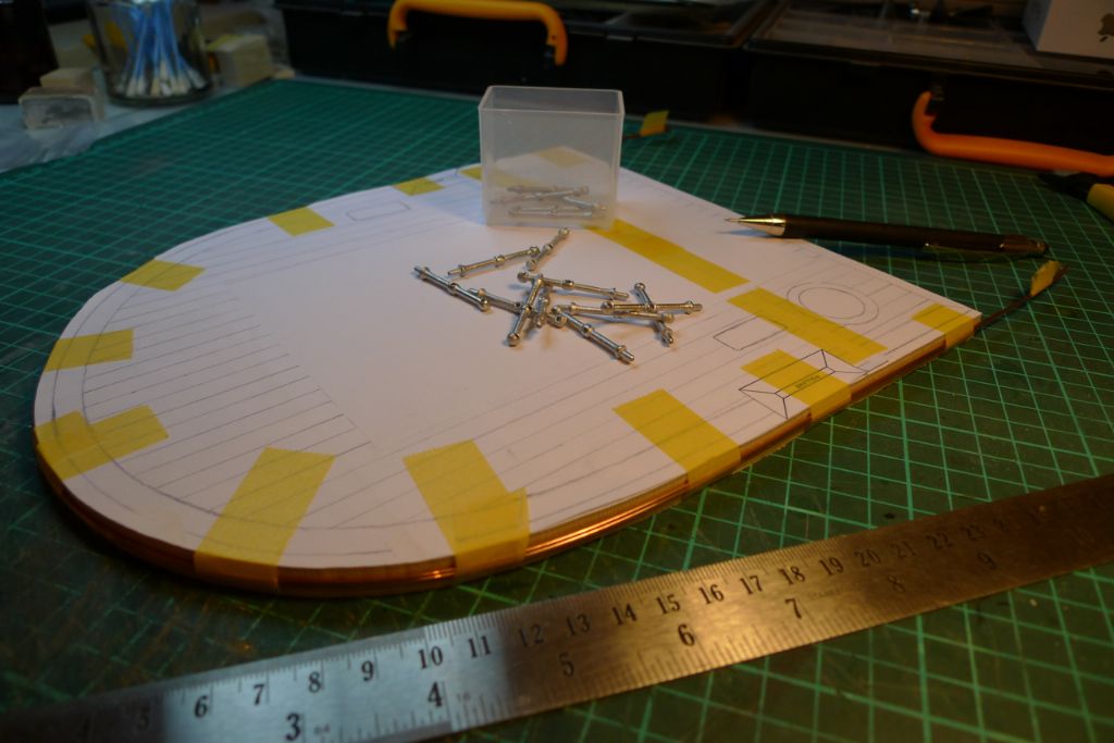
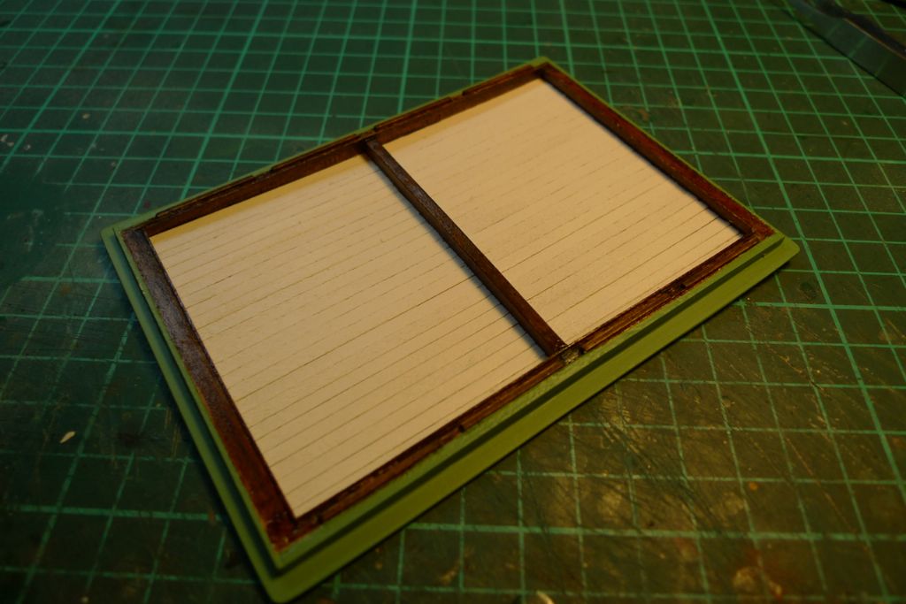
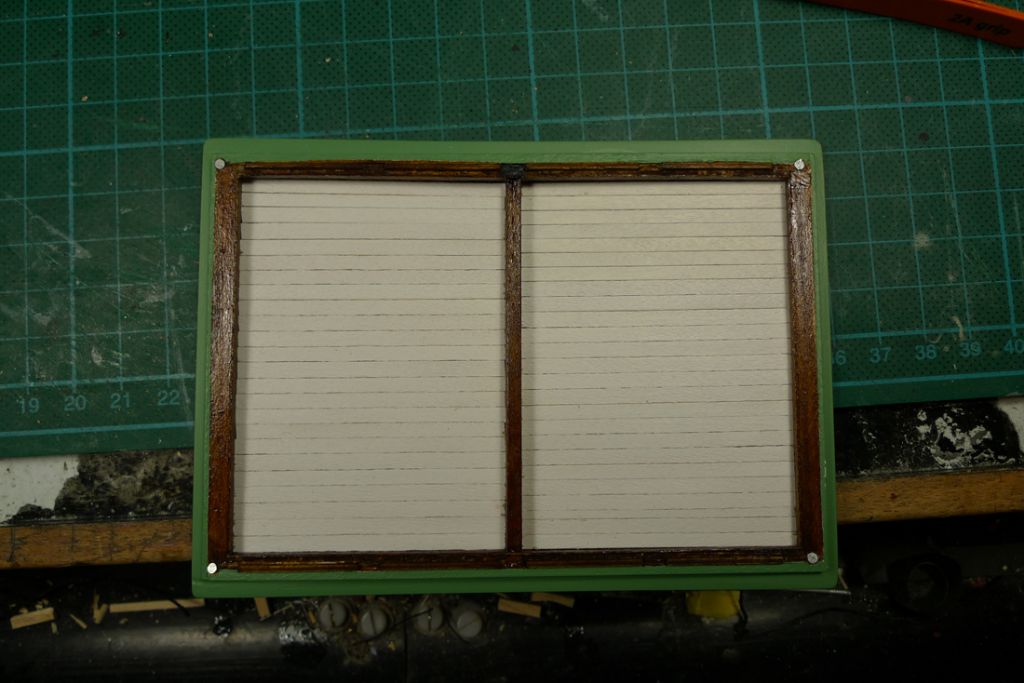
Participant@banjomanThe main hatch was not yet quite finished at this stage. The kit came with a few white metal ringbolts too few (70+ rather than 80+) to accomodate the number of hatch cover boards that there would be if one followed the instructions (which I did). This was not a problem, though: an e-mail to Mountfleet Models resulted in their usual great service and, within the week, an envelope arrived with the required number of additional ringbolts. There was also still the tarpaulin, battens and wedges to be put in place, however I decided to leave these elements for later, and instead moved on to the the quarterdeck and the engine room superstructure.
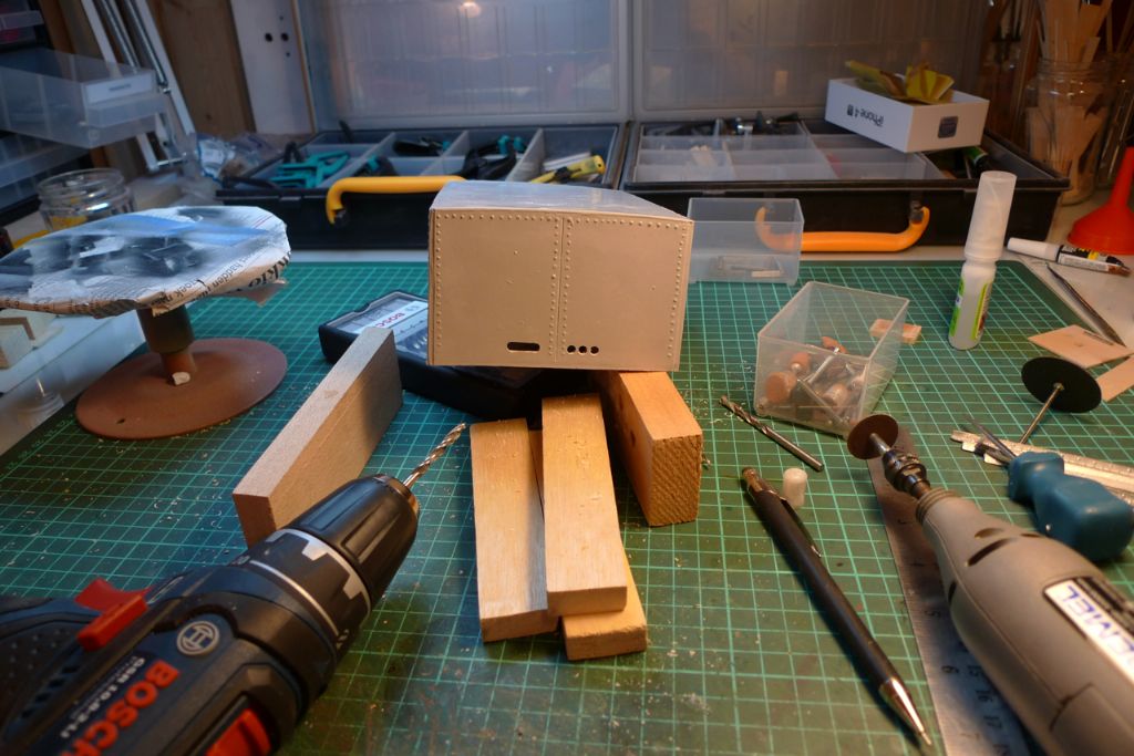
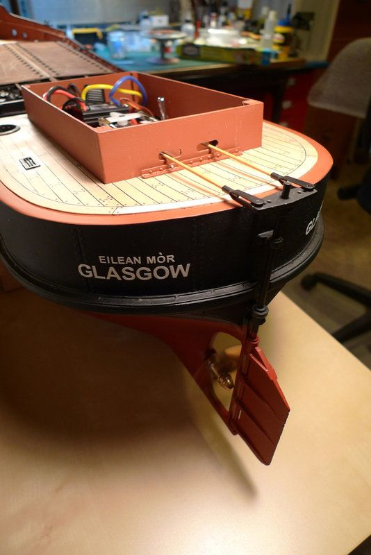
I began this part of the build by drilling the aft bulkhead of the superstructure for passage of the pushrods.
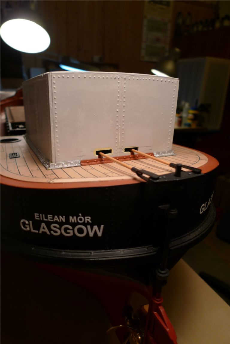
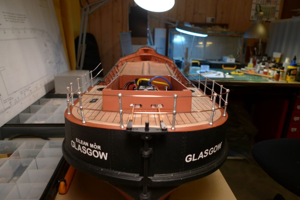
The engine room superstructure will of course have to be removable to allow access to the r/c and driveline installations, which means that it must not snag on the pushrods (which had by now been painted a cream yellow with the links picked out in black). The bit of angle reinforcement to go under the pushrods was therefore painted off the ship, and then glued to the deck …
… at just the right distance for the bulkhead to fit snuggly between the angle piece and the coaming. The other angle reinforcements were then all glued to the lower edge of the engine room.
The pushrod openings were filed to shape (including some minor reshaping with Milliput) and two slots sawed out from the openings to the lower edge of the bulkhead, in line with where the pushrods will stop when the rudder is in neutral position.
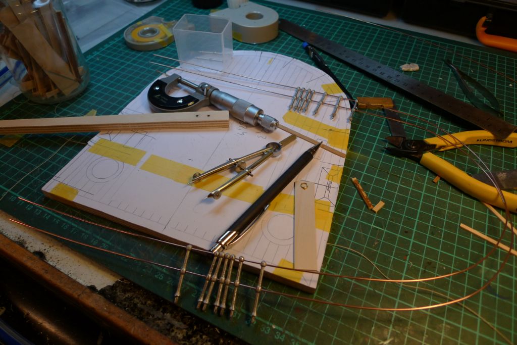
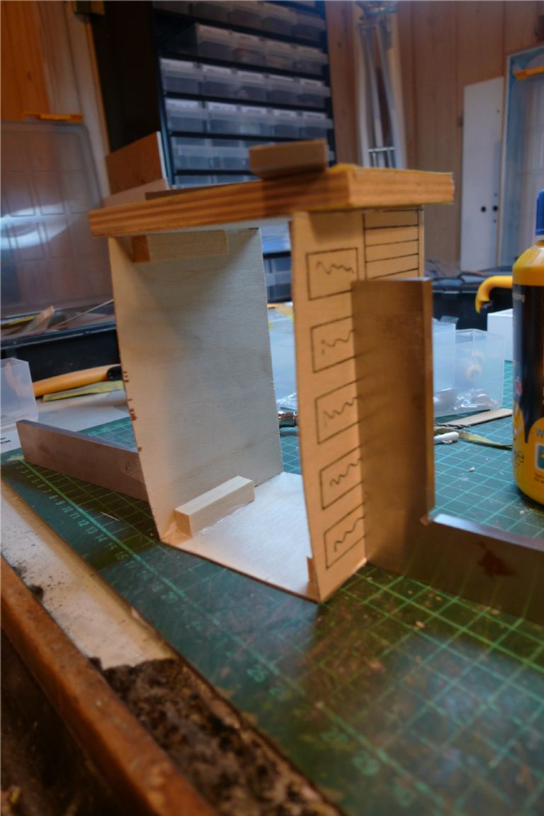
A spare photo copy of my quartereck planking plan was then glued to a piece of scrap plywood, and cut out on the bandsaw to create a former for the quarterdeck railings …
… and also a template on which I could more easily plot out the measurements for distancing the railing supports.
Once the startingpoints and distances for the railing supports had been established, they were marked out on the quarterdeck outer edge with a pair of compasses, holes drilled and the railings dryfitted.
To be continued …
/Mattias
Edited By Banjoman on 26/11/2014 09:15:41
26 November 2014 at 10:08 #53839Banjoman
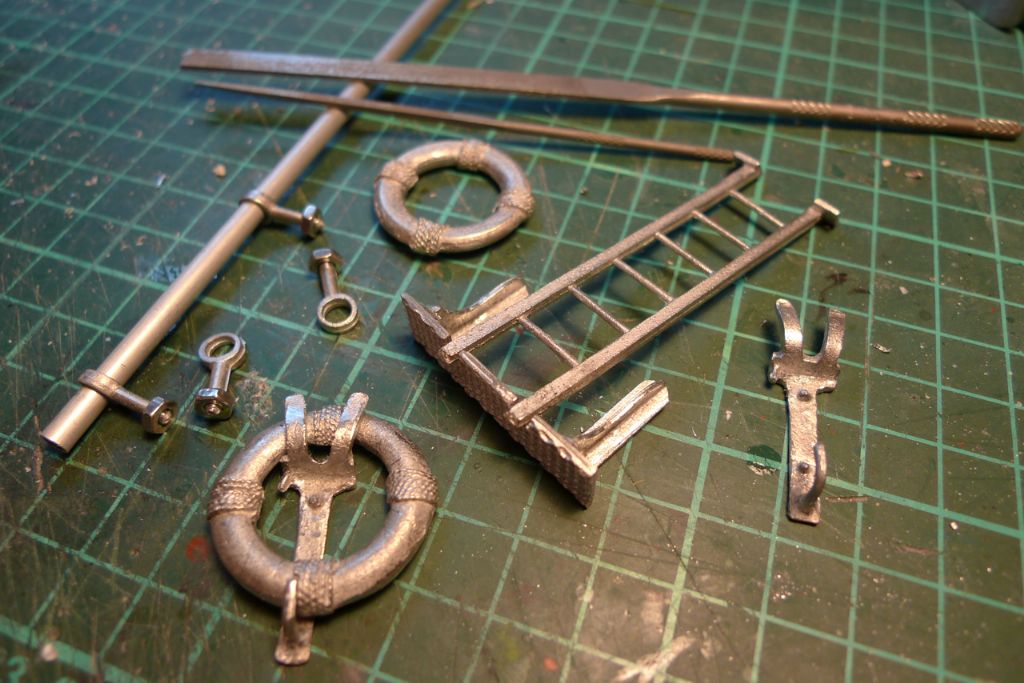
Participant@banjomanNext, I started cleaning up the various white metal fittings to go on the superstructure.
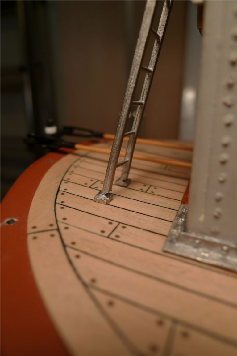
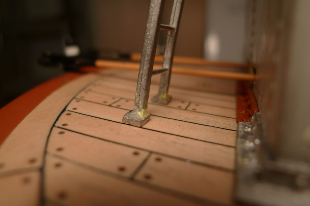
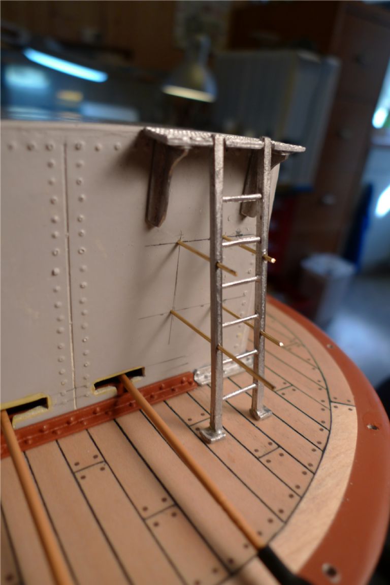
I found at this stage that the wheelhouse ladder had its feet set at the wrong angle to fit properly against the deck with the ladder correctly elevated. This was solved by sawing halfway through the feet, and bending them to fit …
… and then filling the gaps with Milliput.
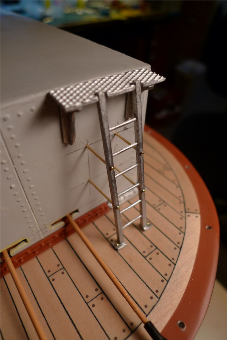
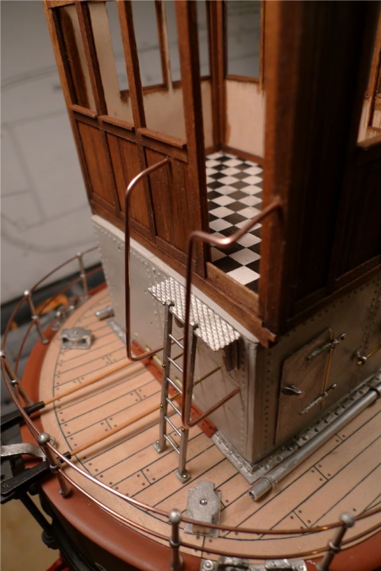
The wheelhouse step plate (and its supports) where then glued in place, and the ladder given some additional strut supports made out of 1.0 mm brass wire …
… trimmed to length and covered with dome headed brass nail heads, some of which were also added to the ladder feet.
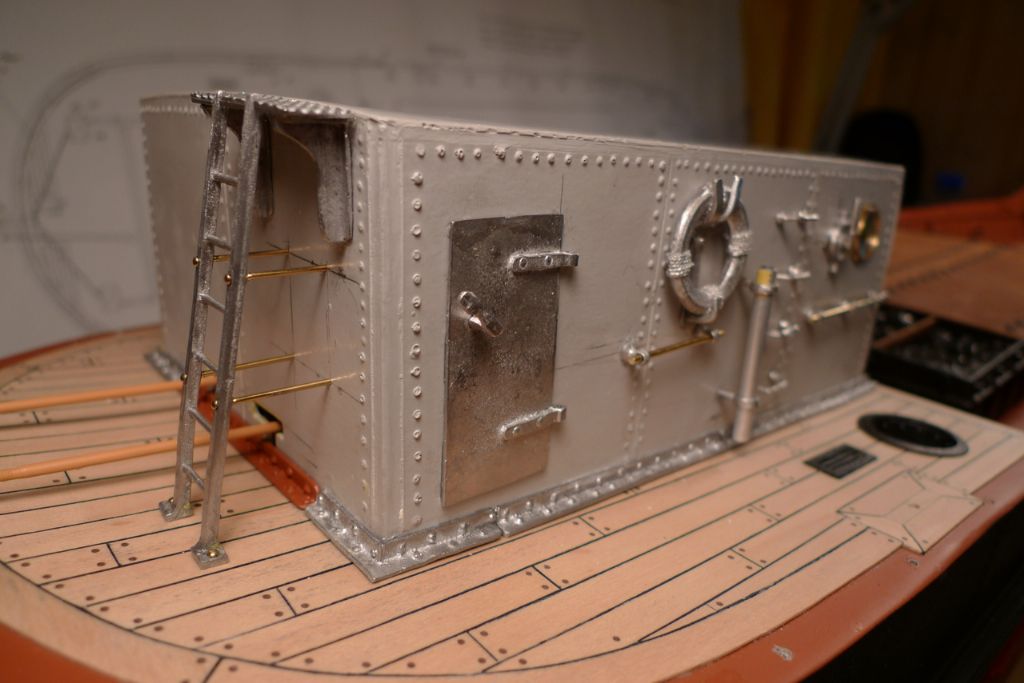
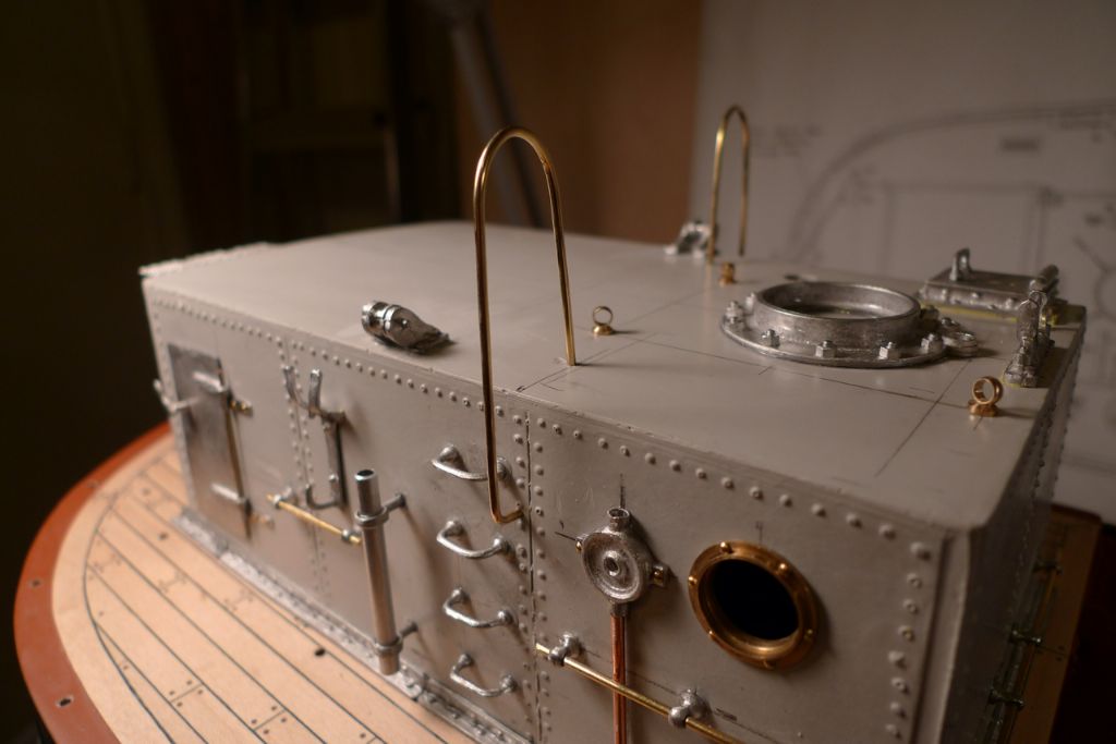
Various fittings were also glued to or dryfitted against the port and starboard engine room bulkheads …
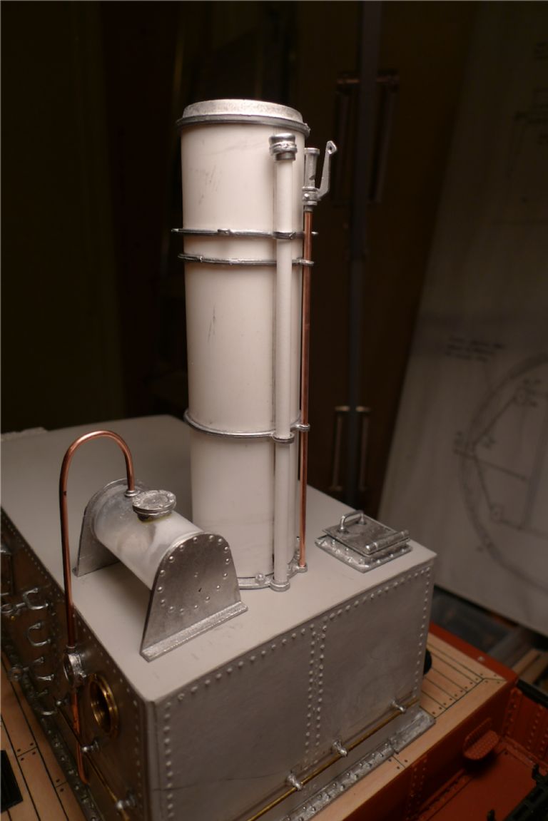
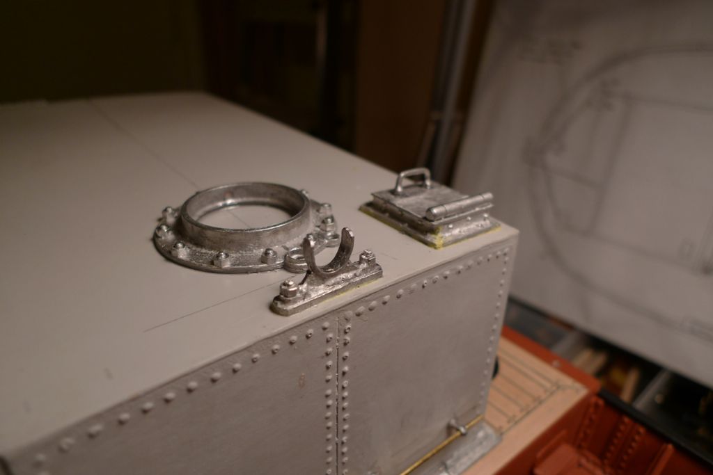
… and also on top of the superstructure, including the chimney together with its own set of fittings.
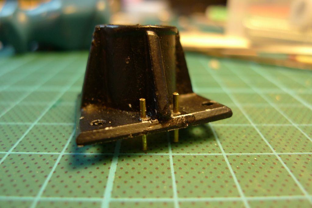
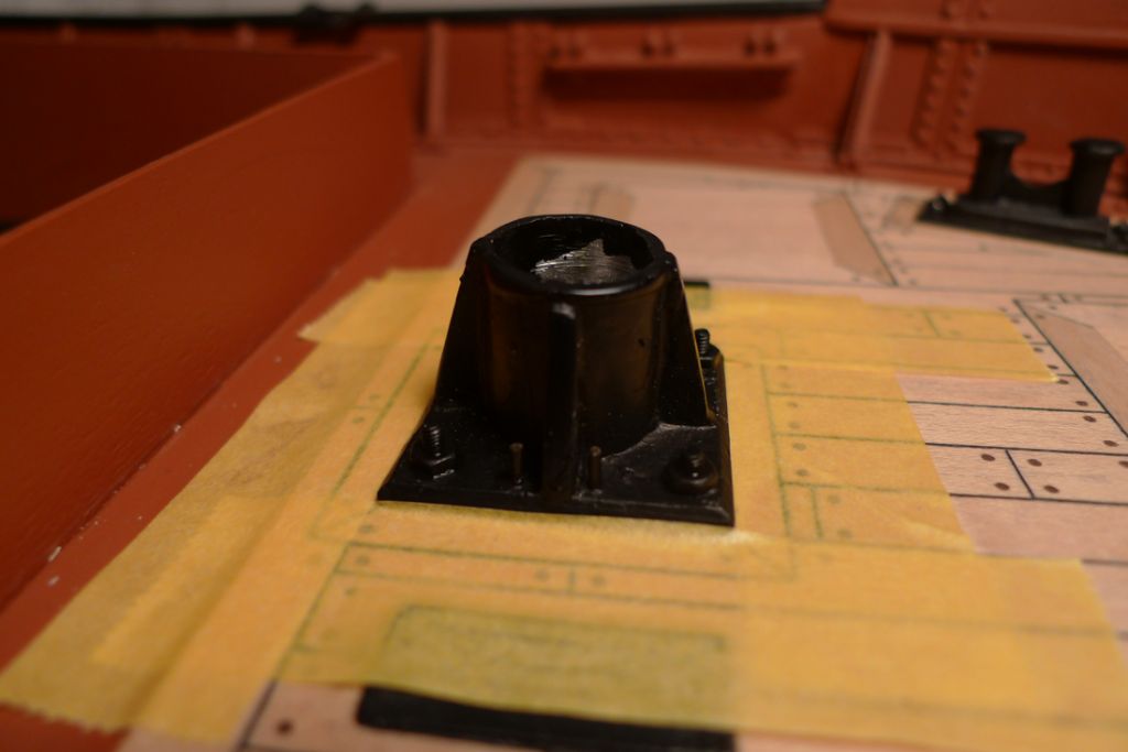
The chimney base was epoxied into place, whereas the boom end support and the engine room escape hatch were secured using Milliput.
Using Milliput instead of a glue for non-flat fittings that need to sit snuggly against a surface has the advantage that by pressing down on the fitting, all crevices or uneven spots are nicely filled. Any surplus is easy to trim off, and because of the slow curing nature of Milliput, one has plenty of time to smooth down the edges with a wet finger and/or wet smoothing tool to a level where hardly any post-curing sanding will be necessary.
Also, if for some reason the joint is not strong enough, and the fitting comes off in the hand, the Milliput willl have formed a perfect fit surface that can then be re-glued with for example CA.
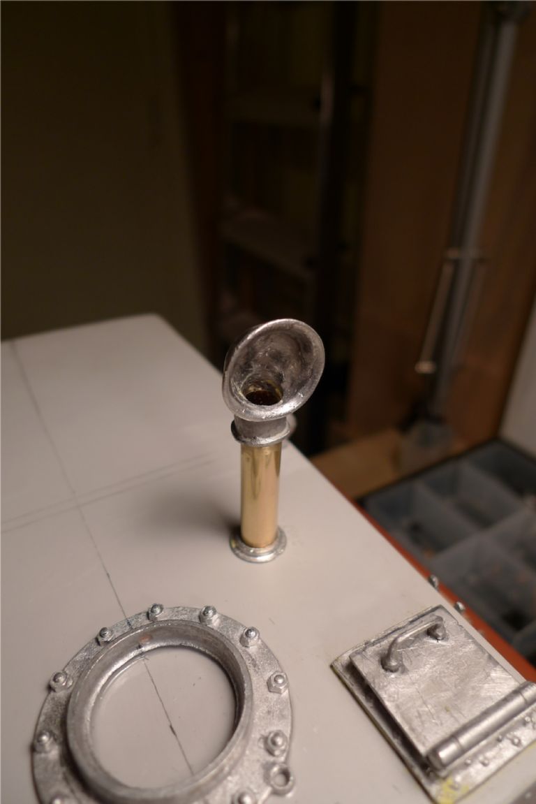
The ventilator head was drilled and filed to open up its base, and then glued onto a shaft made from 8 mm brass tube. After the ventilator foot was added, a piece of 7 mm tube was slid into the bottom of the 8 mm tube, and secured with thin CA, thereby creating a flanged extension that fits through a corresponding hole in the superstructure and makes it sit more securely.
Various other fittings followed, including (replacement) brass eyebolts for securing the chimney stays, handrails for the ladders and the two steering chain rollers — essentially all the fittings to the engine room superstructure that I intended to paint in the same colour as the casing itself.
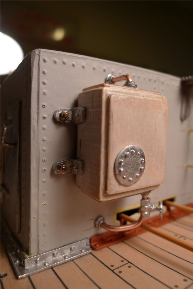
This included the water tank to go on the aft bulkhead, although this would have to be painted separately, as there would otherwise be a spray shadow behind the tank. Instead of just glueing this tank to the bulkhead, I decided to also use some working M1.4 nuts and bolts to secure it.
To be continued …
/Mattias
Edited By Banjoman on 26/11/2014 10:12:28
27 November 2014 at 08:32 #53868Bob Abell 2
Participant@bobabell2A most excellent build, Banjo
Could I make a suggestion?…..Of course……Thank you
Would the rudder bars look better if they were chains?
Bob
27 November 2014 at 19:11 #53902Banjoman
Participant@banjomanHello Bob,
And many thanks for your very interesting suggestion! I've given it a fair bit of thought, but will, I think, stay with the pushrods after all, and this for several reasons:
- Although I'm using a closed loop system for the steering, chains as opposed to pushrods would require more finesse in setting up, as they would only work one way (on the pull) whereas pushrods function both ways (push and pull).
- A (non-functional) steering chain system and a false tiller will be added at a later stage to represent the real-life chain steering typically used on Puffers.
- In think that I would find using chains instead of pushrods for the sake of looks less attractive, because if they are there "for looks" that means they should be looked at, which means they ought to represent something real. However, there was no such chain arrangement in real life, and I therefore find it better to use of pushrods not pretending to be something they're not, compared to attracting attention to a set of chains that are just as unreal but pretend to be something real.
I don't know if the above makes any sense, but I hope you understand what I'm trying to say … ?!
/Mattias
Edited By Banjoman on 27/11/2014 19:14:18
Edited By Banjoman on 27/11/2014 19:15:10
27 November 2014 at 19:54 #53905Bob Abell 2
Participant@bobabell2Good answer, Banjo!
Bob
28 November 2014 at 12:27 #53934Banjoman
Participant@banjomanWith most of the engine room superstructure details in place, it was time to look at the wheelhouse.
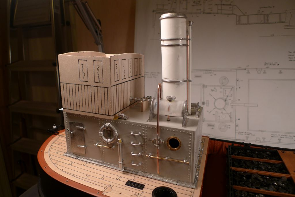
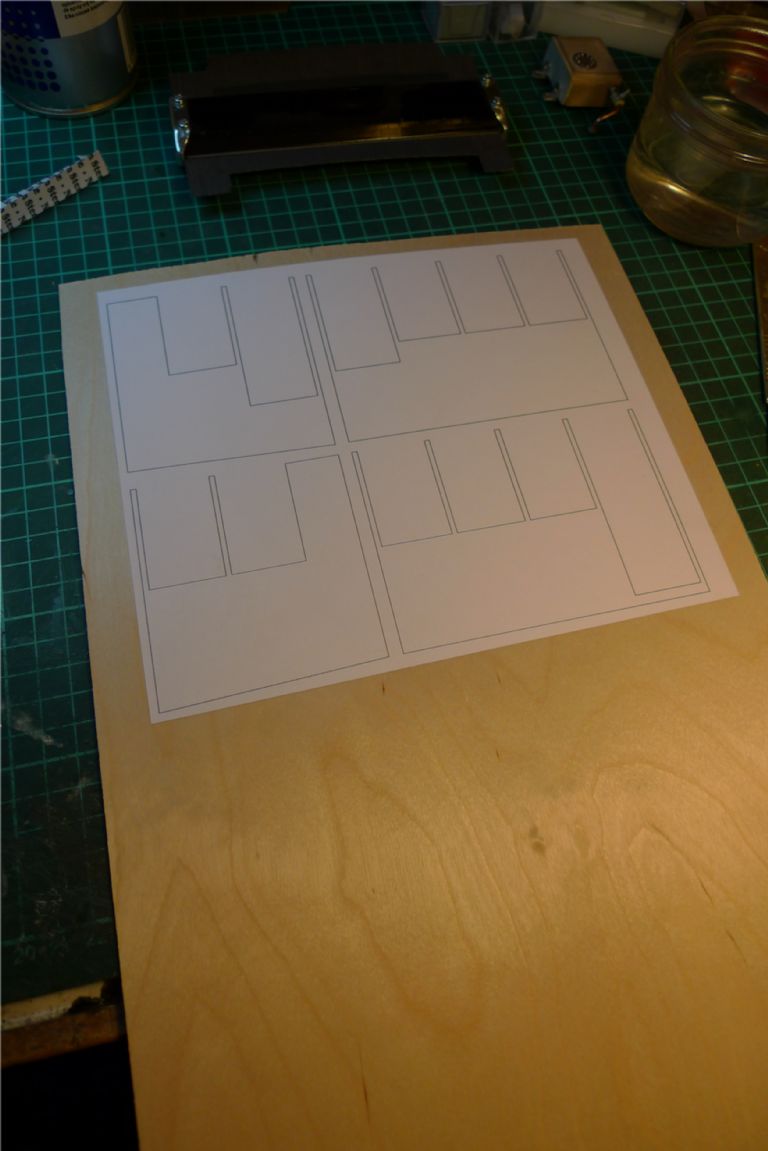
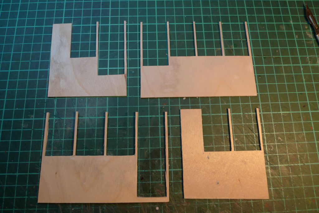
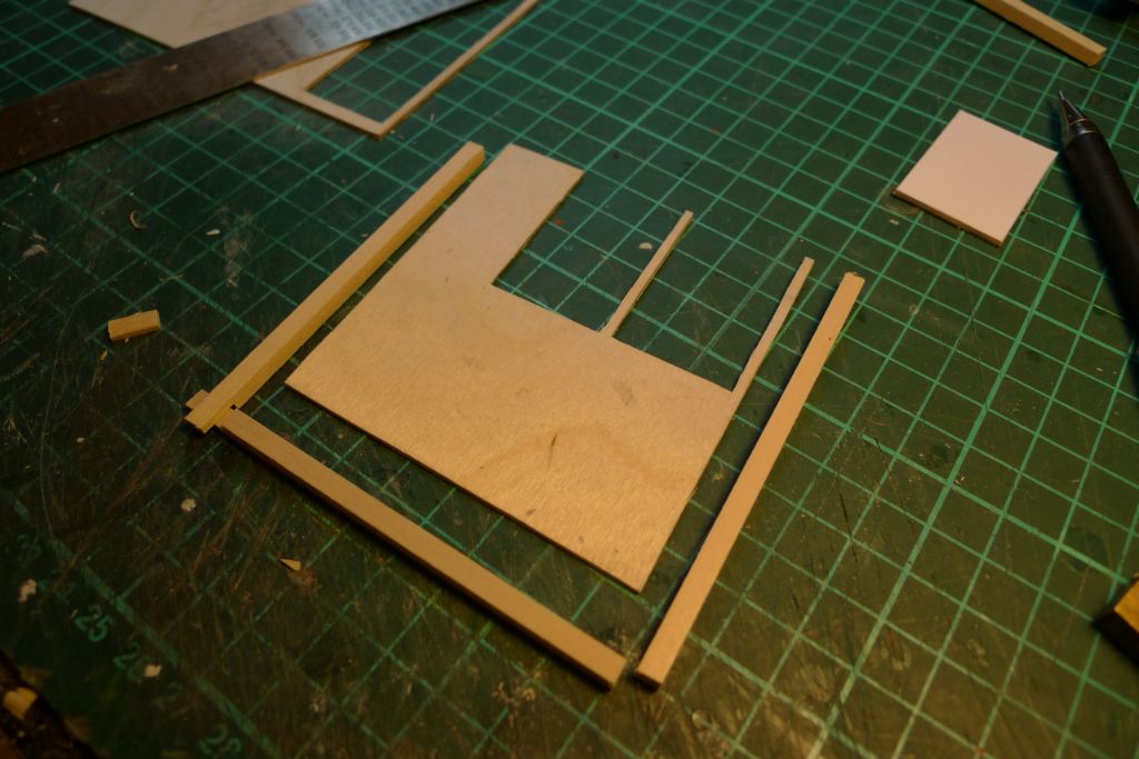
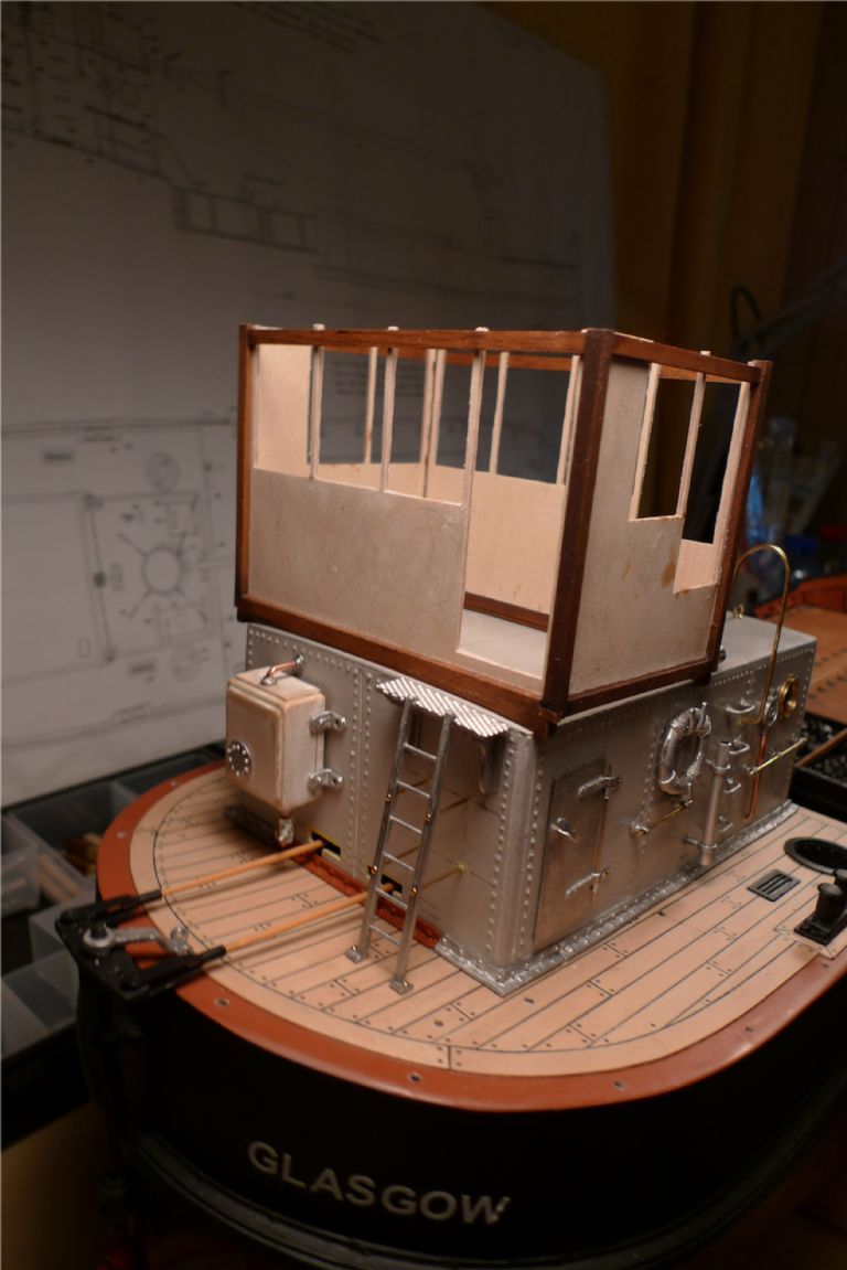
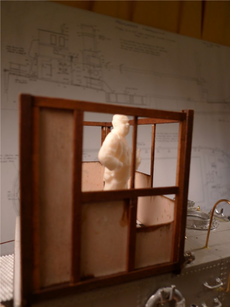
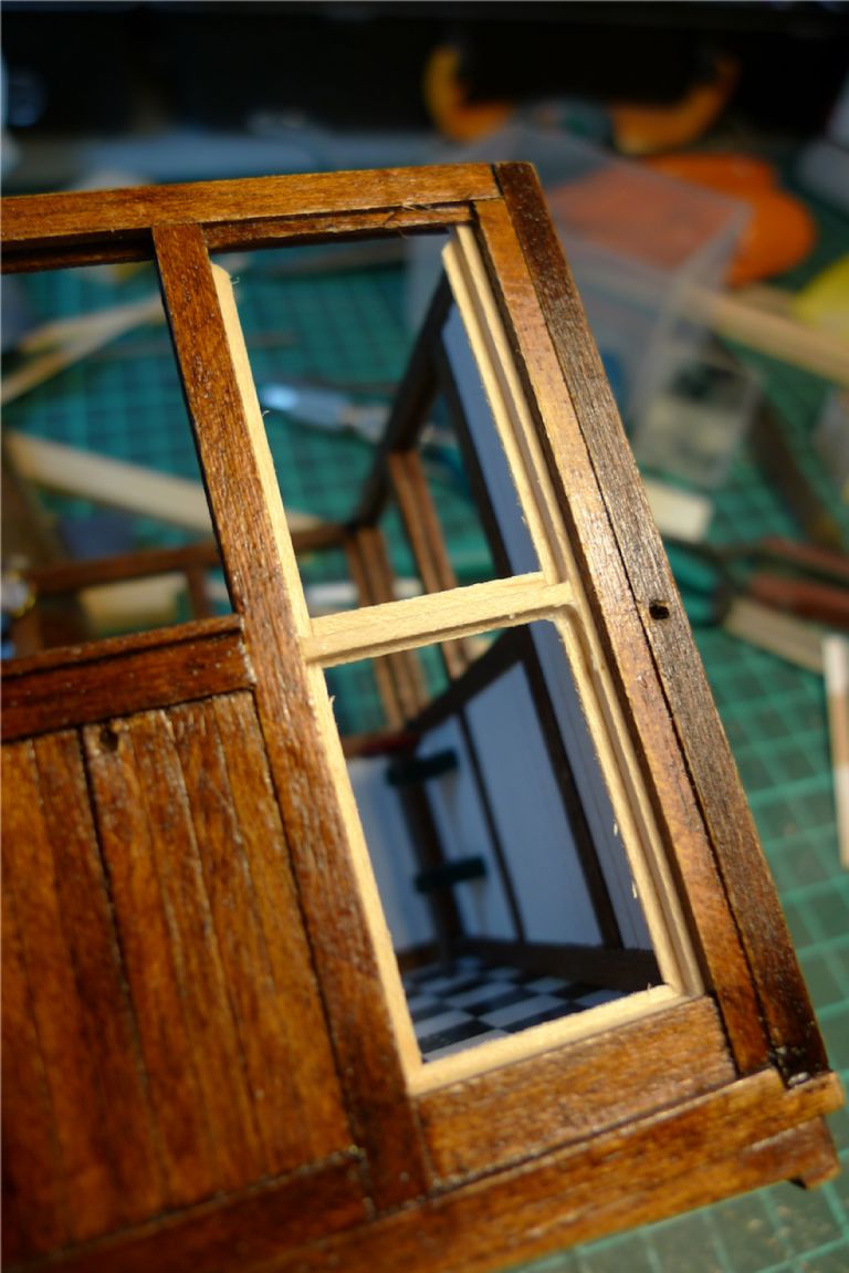
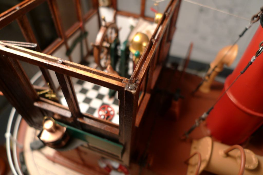
The kit came with printed plywood cutouts to form the sides of the wheelhouse. I had already decided to discard these, same as I did with the deck overlays, in part because I didn't really like the design (too small windows) and in part because I thought it would look nicer with a more threedimensional construction.
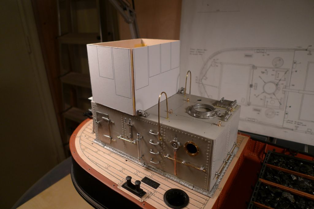
I nevertheless cut the printed sides out and cobbled them together …
… in order to verify the size of the wheelhouse as suggested by the kit parts. I found that the dimensions provided for were on the whole fine, although I did decide to make the structure a few mm taller and deeper.
With a good enough idea of the suitable dimensions, I sat down at the computer to plan the construction in more detail, taking into account the dimensions of the materials I intended to use.
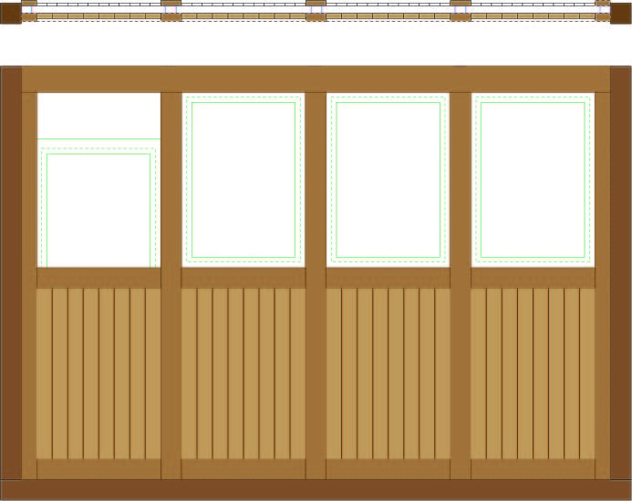
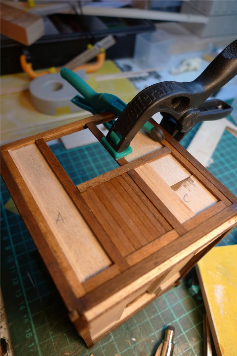
My plan was to go with a sandwhich construction, with a 1,5 mm plywood core, framed by 4×4 mm maple square dowel and planked inside and out with a combination of 0.5×3, 0.5×4, 1×3, 1×4, 1.5×3 and 1.5×4 mm maple strip.
This way, all differences in depth between two adjoining pieces of timber would be 0,5 mm which at full scale would equal 12 mm. This is a tad exagerrated, perhaps, but not completely unrealistic either: if one looks at, for example, a panelled door, the differences in level tend to be between, say, 8 and 16 mm. By going with this difference, I could also use standard strip wood as available from a number of our favourite dealers.
Below is the front and top elevation of the fore wheelhouse side as I designed it. The sandwhich construction creates slots for sliding the window frames into, and I decided to build for having two of the windows (one of which is shown here) in a partially open position.
The basic shapes of the plywood cores were then extracted from my design drawings, printed out and spray glued onto some 1.5 mm plywood. The port and starbord sides were set at a 2.5 degree angle, to correspond to the sheer of the engine room roof.
The resulting sides were then temporarily attached with some masking tape, to check the general fit of the basic dimensions …
… and as these met with renewed approval, the window and door openings were cut out.
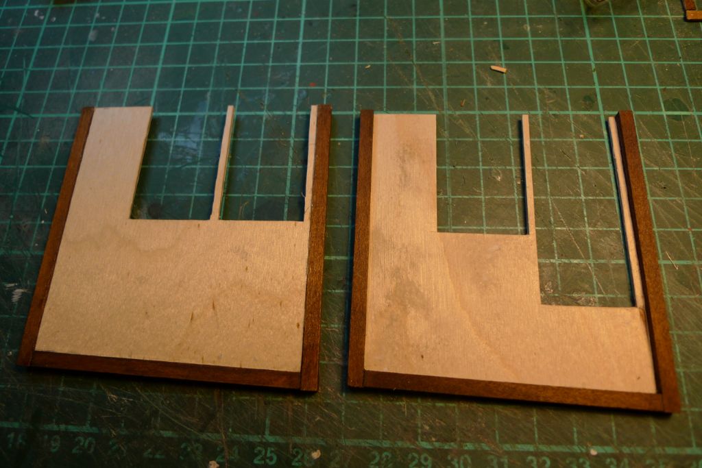
The port and starboard sides were then given a surrounding 4×4 mm framework, morticed at t he corners.
The framework was glued to the cores in such a way that the core sat 1 mm from the inside edges of the frames and 1.5 mm from the outside edges.
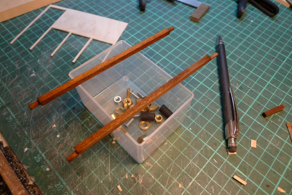
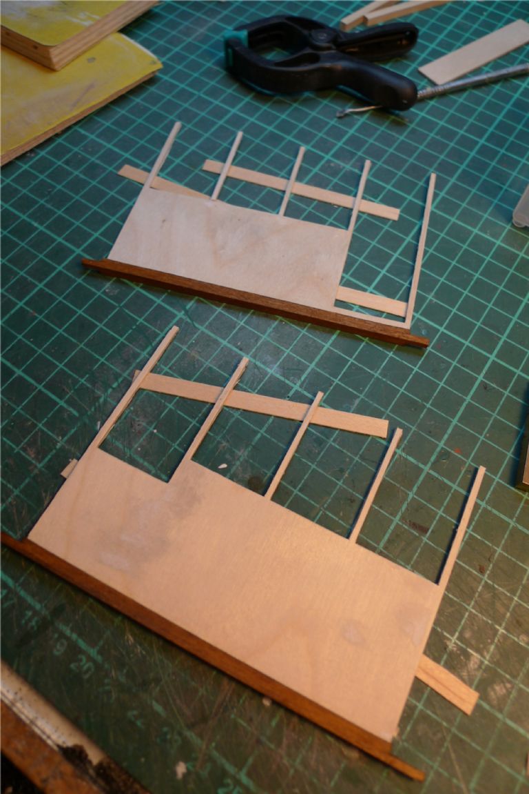
Next, two athwartships beams were produced, also morticed …
… and then glued to the ore and aft sides.
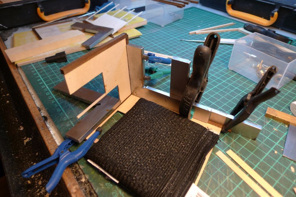
Finally all four sides were joined together at right angles …
… and tested atop the engine room. Because of the engine room athwartships camber, two additional underlying beams were shaped and glued to the bottom of the two main traverse beams to form a decent fit and to lift the whole wheelhouse up a few mm from the egine room top.
To be continued …
/Mattias
Edited By Banjoman on 28/11/2014 12:29:34
28 November 2014 at 18:10 #53949Banjoman
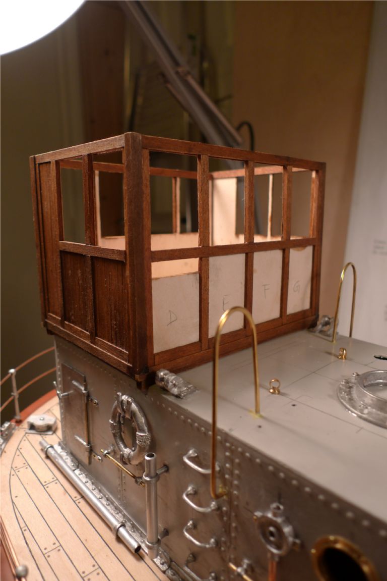
Participant@banjomanWith the basic wheelhouse shape and structure in place, I began panelling it by adding a "mock tudor" framework effect along all four sides, made up from 1.5×4 mm oak-stained maple strip.
I then planked each resulting panel using similarly oak-stained 1×3 mm maple strip …
… graduallycovering the sides …
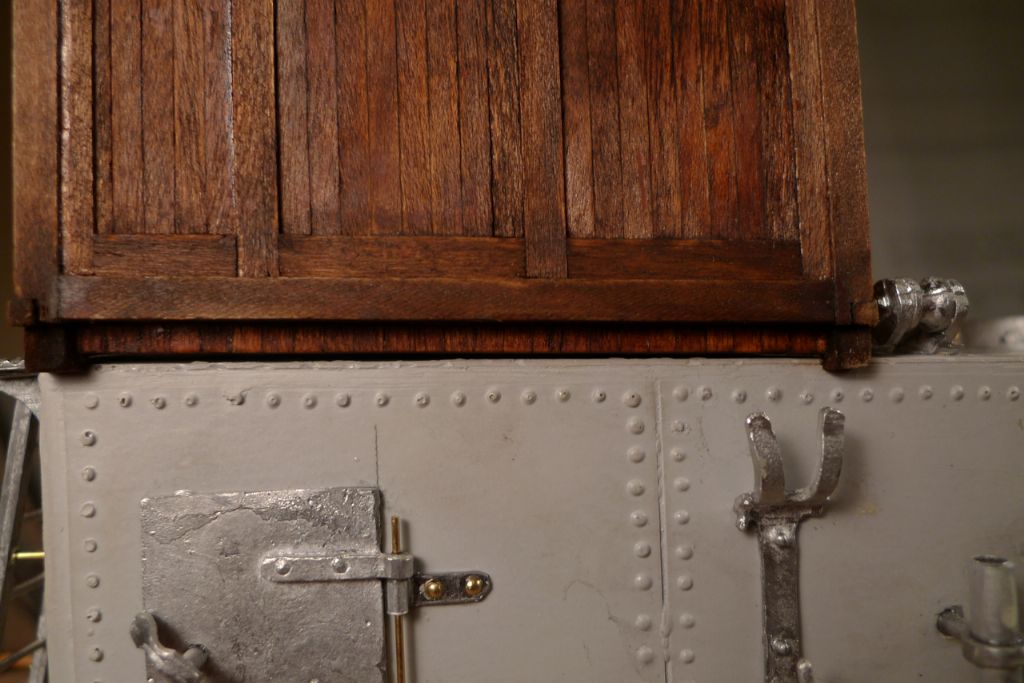
… including a row of panelling along the bottom edges on the port and starboard sides, to cover up the inner workings — two M4 brass flathead bolts countersunk into the false floor of the wheelhouse. This allows the wheelhouse to be bolted down onto the engine room, which of course means a stronger bond than glue can give, but also that I could remove and refit the wheelhouse in exactly the same position time and time again, as I was working on it, alternately off and on the model.
A pair of handrails where also added to the wheelhouse ladder and step plate. The below photo also shows the false tiller, the rear deck steering chain rollers, the fairleads and the steering chain tubes, all just dryfitted as yet.
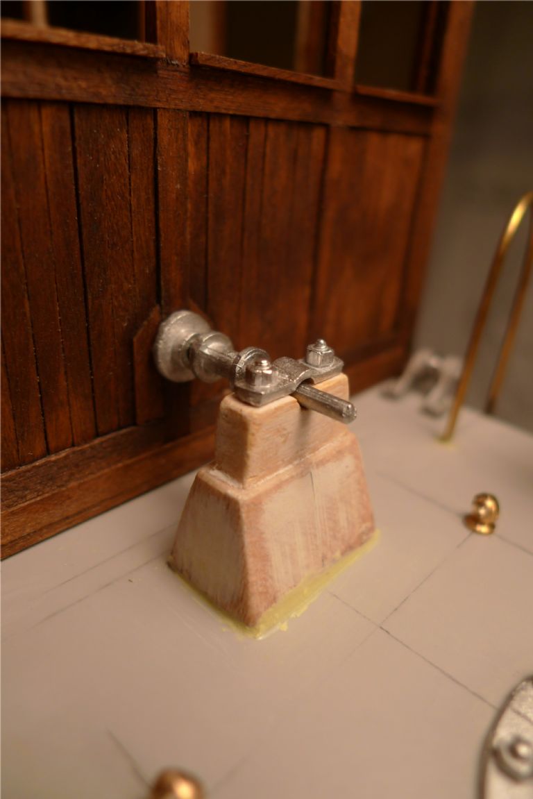
Forrard of the wheelhouse, a steering chain wheel axis support was added, again secured with a slice of rolled-out Milliput.
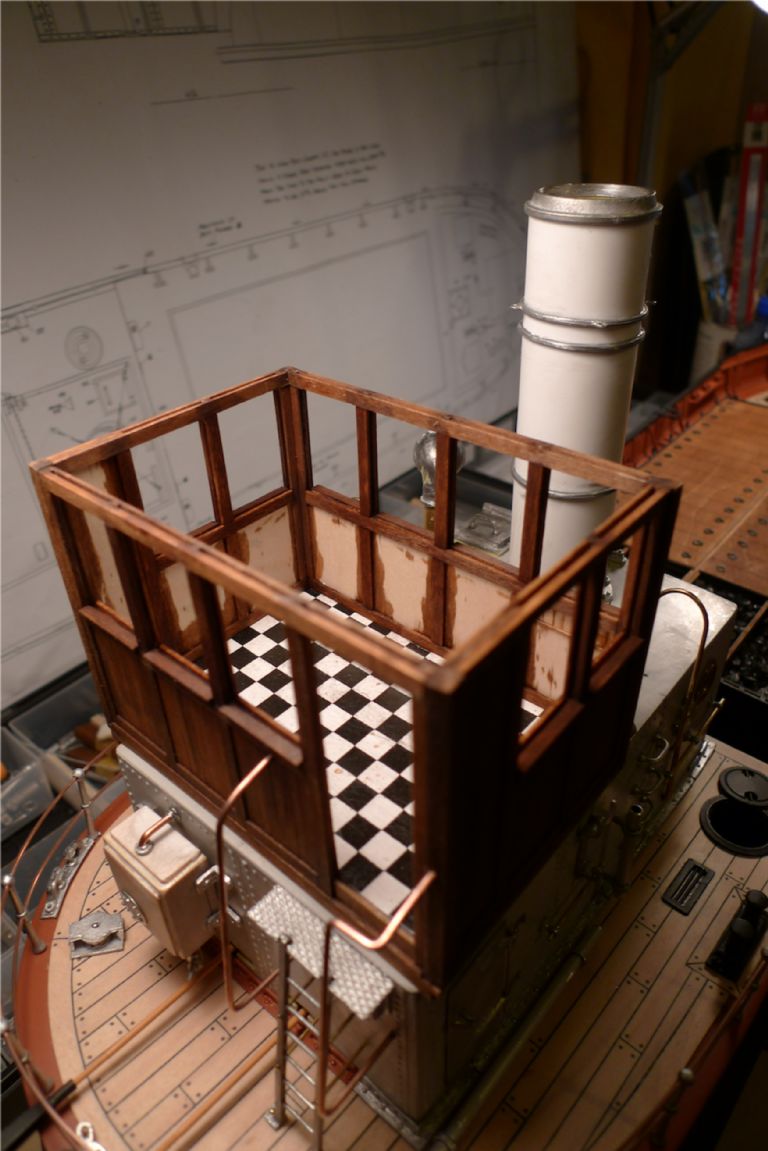
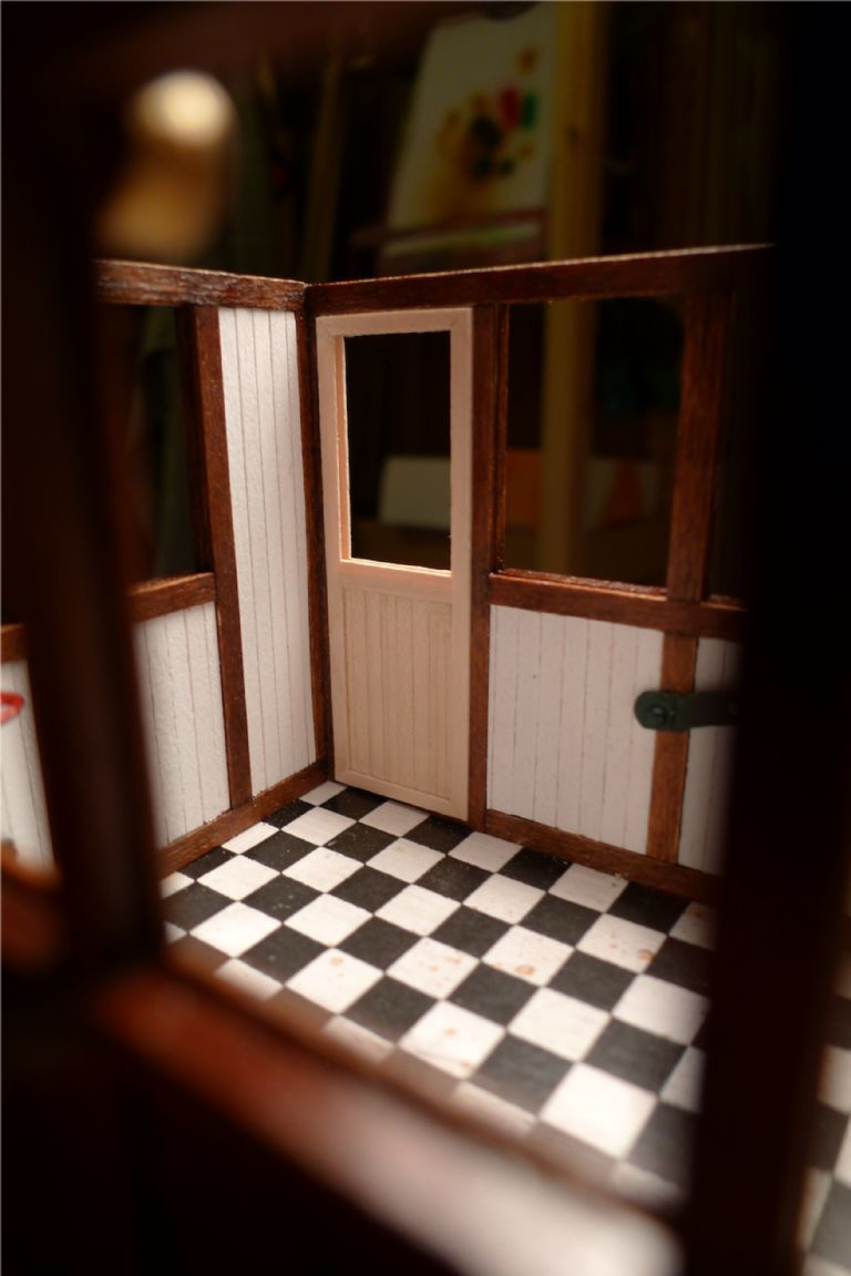
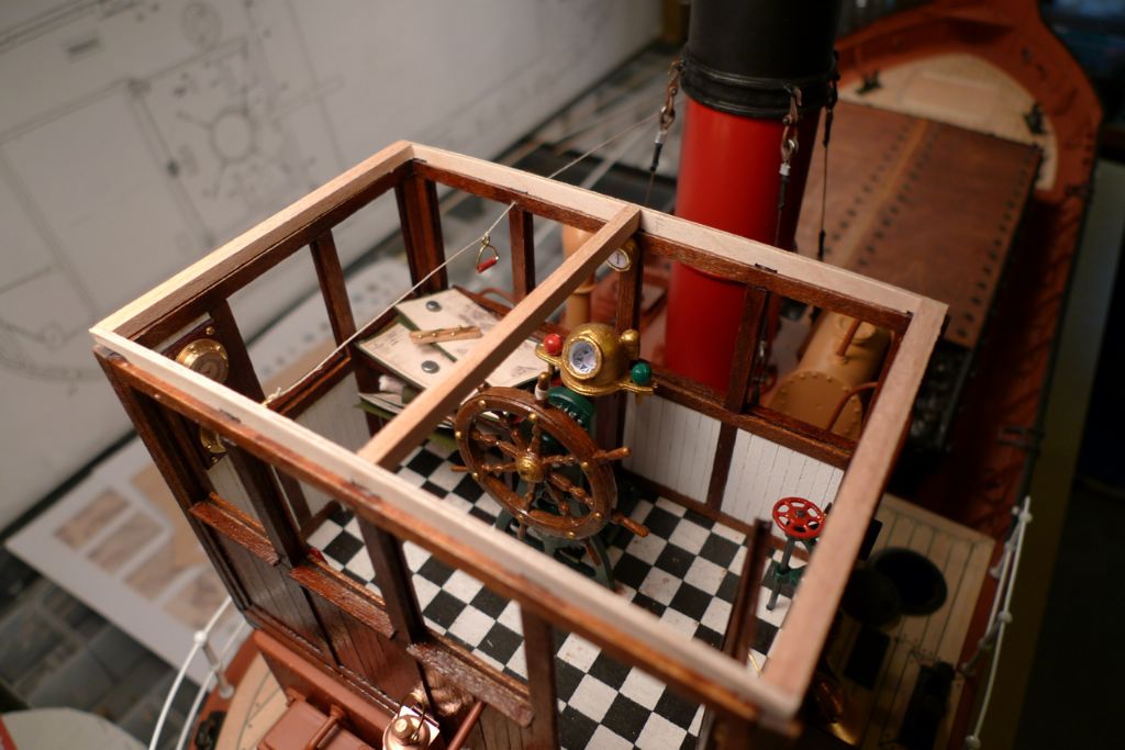
On top of the false wheelhouse floor I then added the "real" floor, i.e. some thin plywood to which was glued some paper printed in a black-and-white checker pattern that came with the kit. This was then given a couple of coats of gloss varnish to make it a bit more linoleum-y.
Speaking about the wheelhouse floor, I should add that I realised when fitting the basic wheelhouse structure that the engine room superstructure is not perfectly square, and in order not to give this away by having a true square wheelhouse sitting at an angle to the aft end of the enginge room, I had to give the whole wheelhouse just a wee bit of a twist; not much at all, just enough to create the effect of what I like to call optical symmetry as opposed to mathematical.
Because the eye will liine up the main shapes, i.e. the edges of the engine room and the placement of the steering chain riollers just forrard of the wheelhouse with the wheelhouse sides, if these lines look true it creates the illusion that the whole is square, whereas in fact it is ever so slightly lozenge-shaped.
The twisted shape was then secured by cutting both floor pieces to that precise shape.
At this stage I also added the main panel framework on the insides as well, but for the moment left off planking those panels, until I knew how I wanted to proceed with the electrical installations for the navigation lights.
To be continued …
/Mattias
1 December 2014 at 11:55 #54021Banjoman
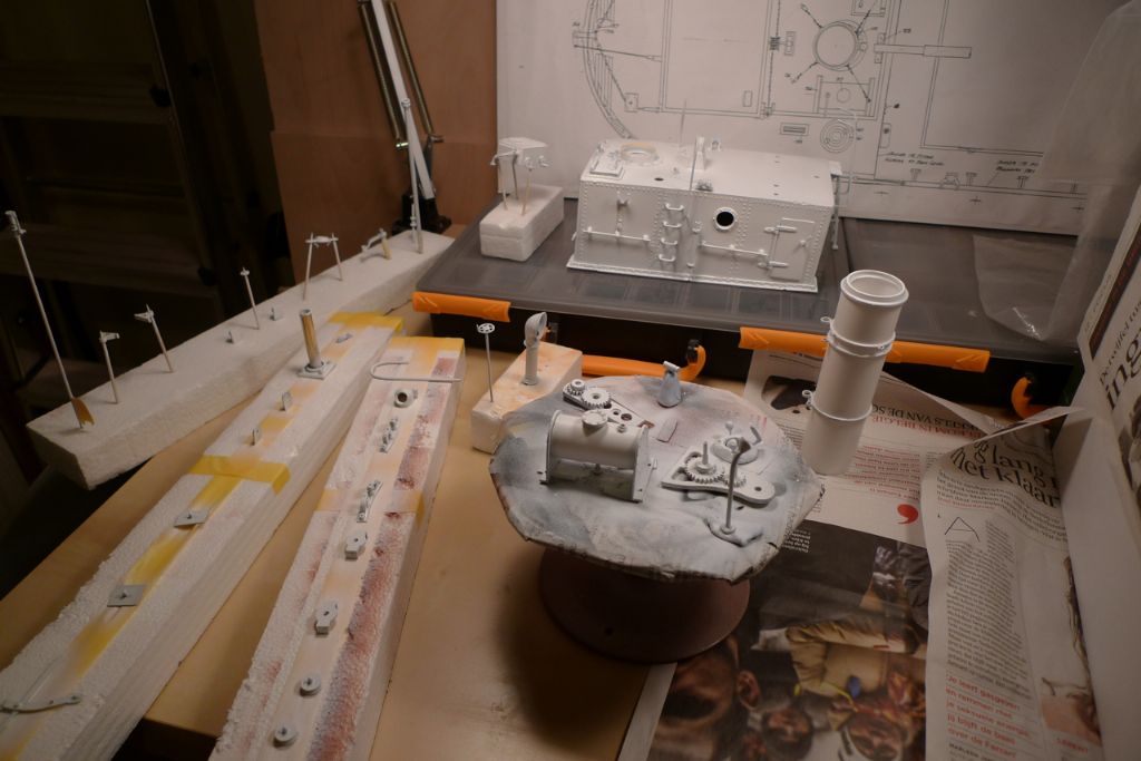
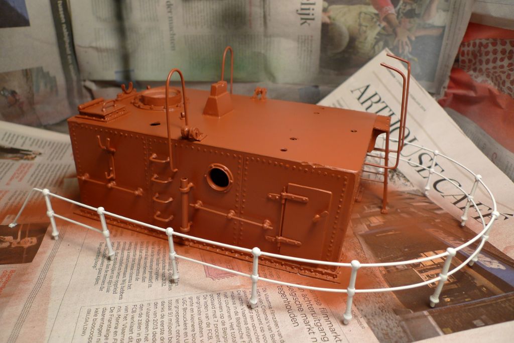
Participant@banjomanWith the wheelhouse externals largely finished, it was finally time to get some paint on the engine room superstructure, and also on quite a few of the quarterdeck, engine room and wheelhouse details.
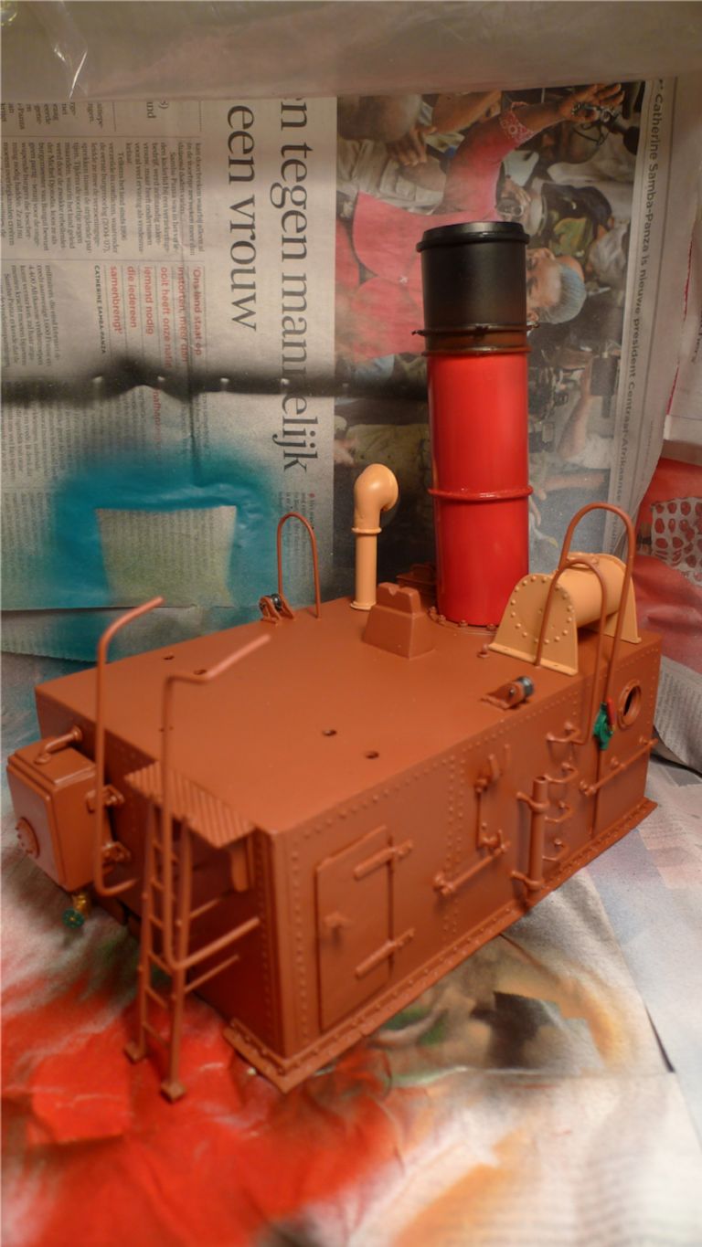
The superstructure was painted in the same reddish-brown that I'd already used for the decks and bulwark insides, while the quarterdeck railings were painted white and then given a few coats of gloss varnish to give the effect of a gloss enamel anti-rust paint.
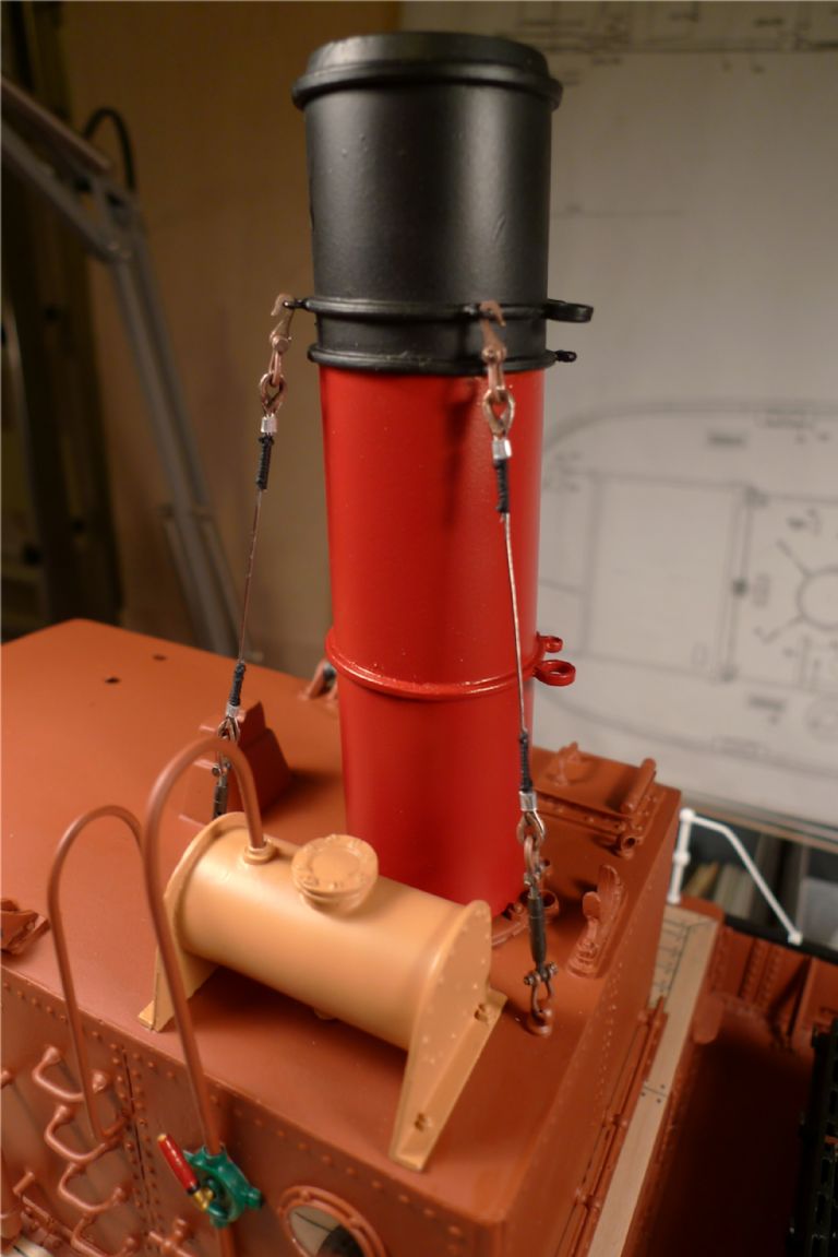
The chimney was painted bright red with a black topping. I decided not to go for any specific shipowner's livery here, but just a generic (and fairly classic) red-and-black paint scheme. The tank and ventilator were painted cream yellow, with the inside of the ventilator cowl picked out in bright red. The tank feed hand pump housing was painted green, and the steering chain roller wheels gun metal grey.
The chimney was also set up with stays, the first two of which can bes seen in the photo below, made up from all non-kit parts: 0.5 mm steel wire rope and working brass bottle screws from Eskader in Stockholm, cast bronze thimbles from Modelling Timbers, RB Model working shackles and etched brass rigging hooks. The thimbles were secured to the wire ropes using short pieces of aluminium tubing through which the wire was taken and the tubing then squeezed flat with a pair of pliers, after which the wire ends were served with black riigging thread.
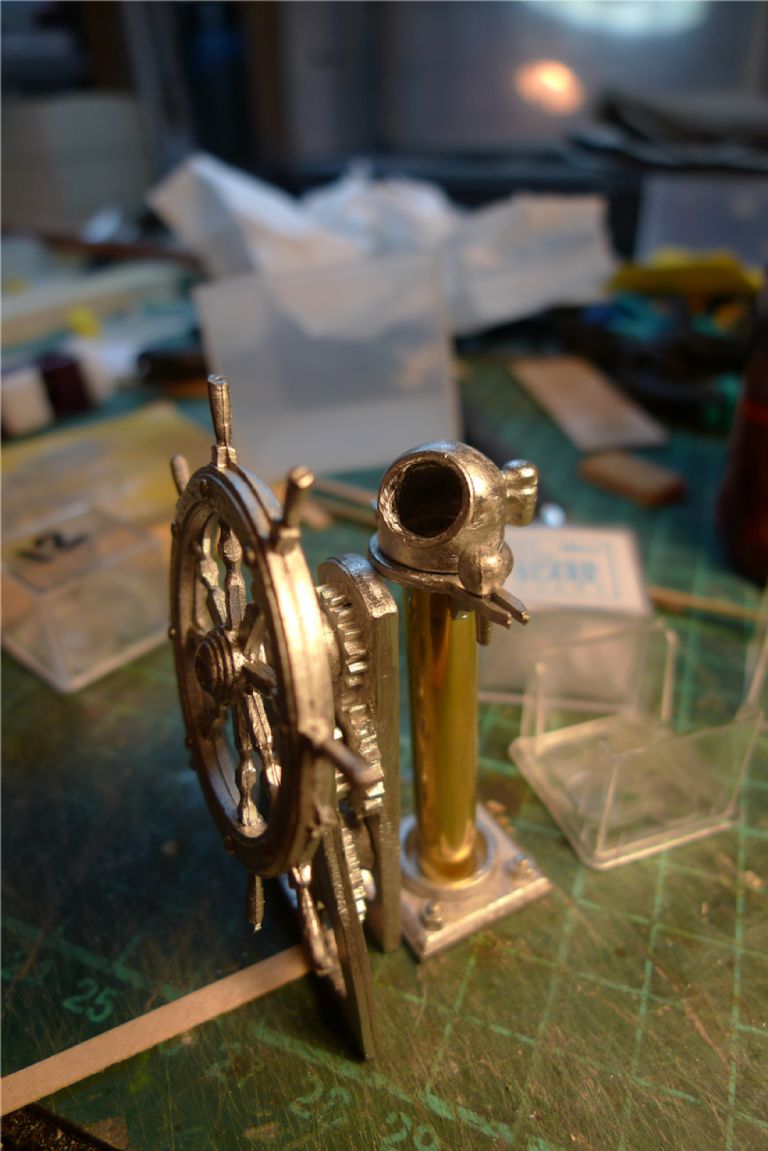
I also started on some of the wheelhouse interior detailing, first of which was the binnacle. The instructions suggested using dowel for the pillar base, but as I wanted to add internal lighting, I instead went with a short length of brass tube.
Together with the binnacle, I also began cleaning up the ship's wheel and the wheel standard and steering gears.
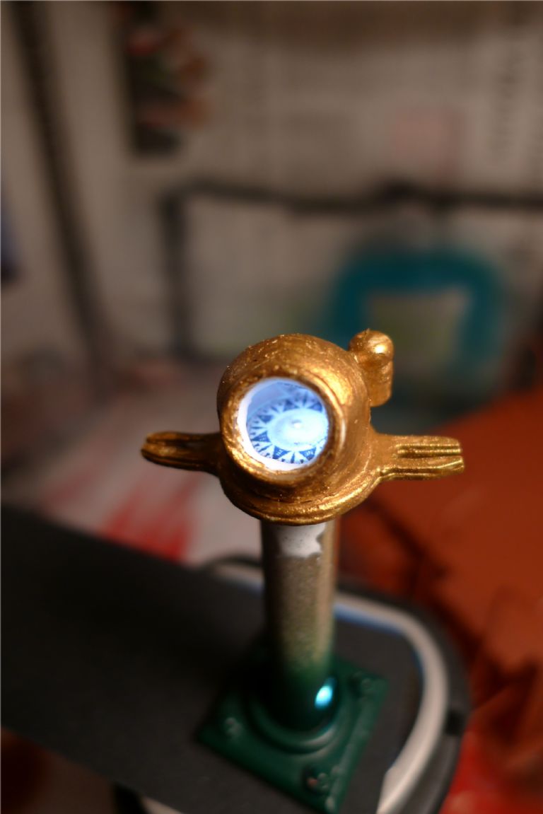
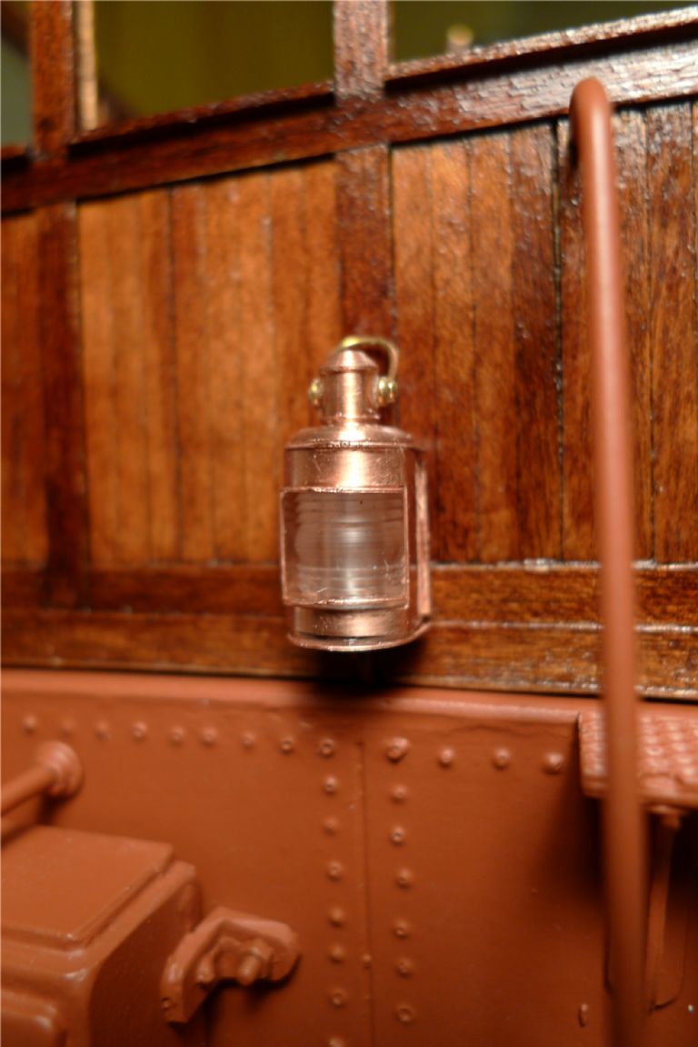
The binnacle hood was painted brass, and a BECC compass rose decal added that sits on a 10 mm round microscopic slide cover glass, while an 8 mm slide cover glass was glued into the binnacle opening. A 3V grain-of-wheat bulb in the brass tube pillar gives a suitable light, that can be slightly varied in intensity by how hogh or low in the pillar it is made to sit.
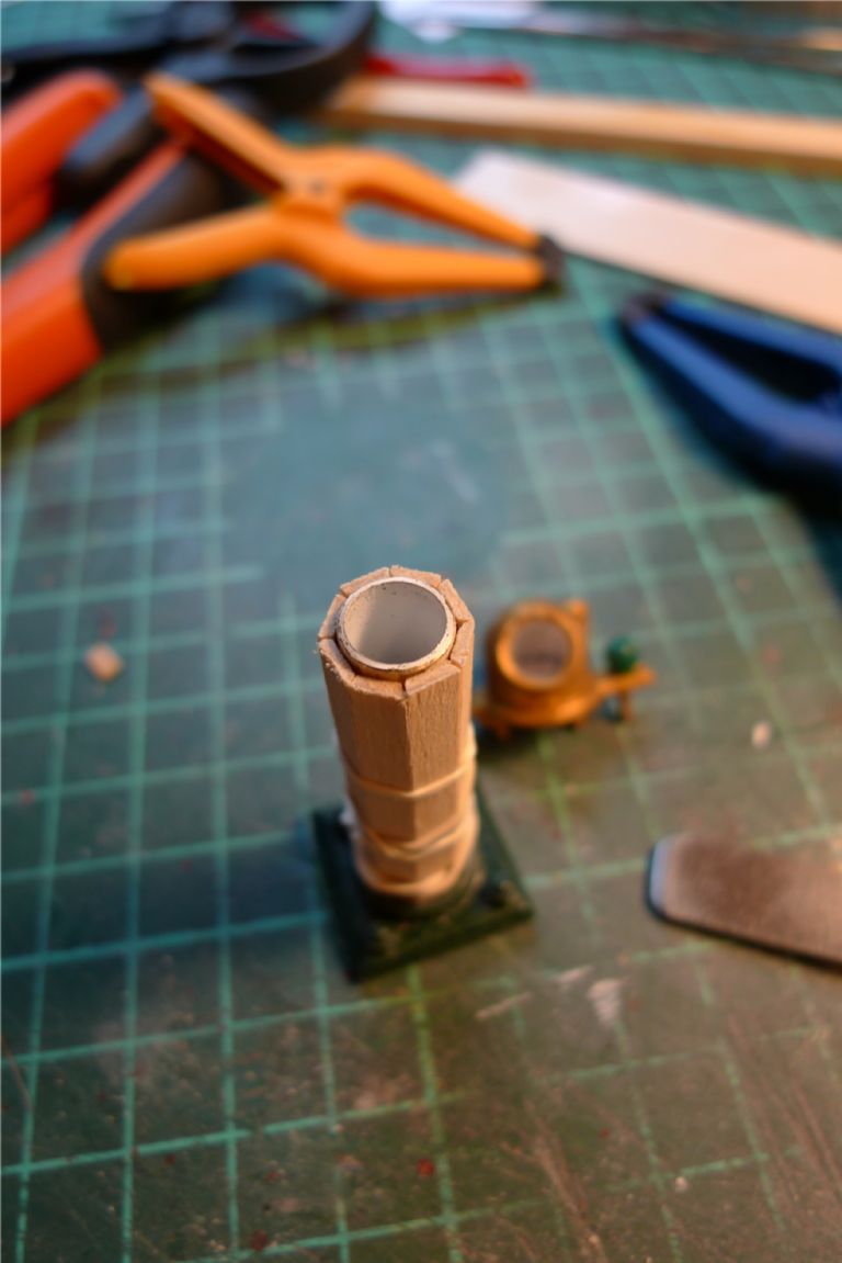
By tilting the bandsaw table to the correct angle, a length of maple strip was bevelled on both edges and then cut into suitable lengths to make up the base pillar wood covering …
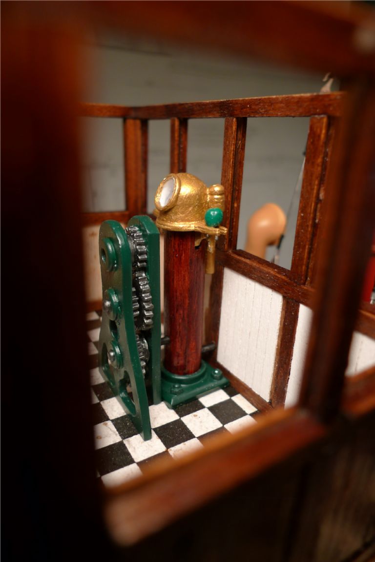
… which was then stained mahogany and given a couple of coats of gloss varnish. The wheel standard and binnacle base plate were painted dark green, the steering gears gun metal and the deviation balls in the usual red on the port and green on the starboard side.
In parallell with the above-mentioned painting I also began panelling the inside of the wheelhouse white 0.5×3 mm maple strips painted white.
To be continued …
/Mattias
1 December 2014 at 12:20 #54022Banjoman
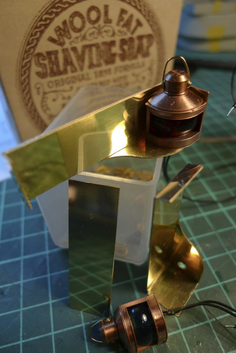
Participant@banjomanNext up were the lightboards for the port and starboard navigation lights. These were from etched brass that had to be folded into shape, glued together and in a few places given a light additional filling of Milliput.
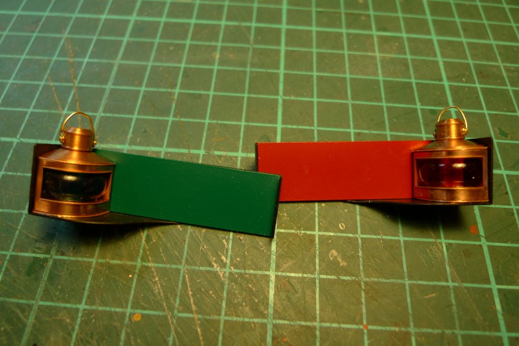
Just as the lights themselves, they are from Marten, Howes & Baylis, and (I believe) originally parts for their "Vigilant" kit. A nice feature of these lightboards were the separate brass plates to be painted with the appropriate backing colours …
… of green and red respectively, which meant that these colours could be sprayed on before final assembly, thereby ensuring a nice, crisp separation of colour from the black I chose for the lightboards themselves.
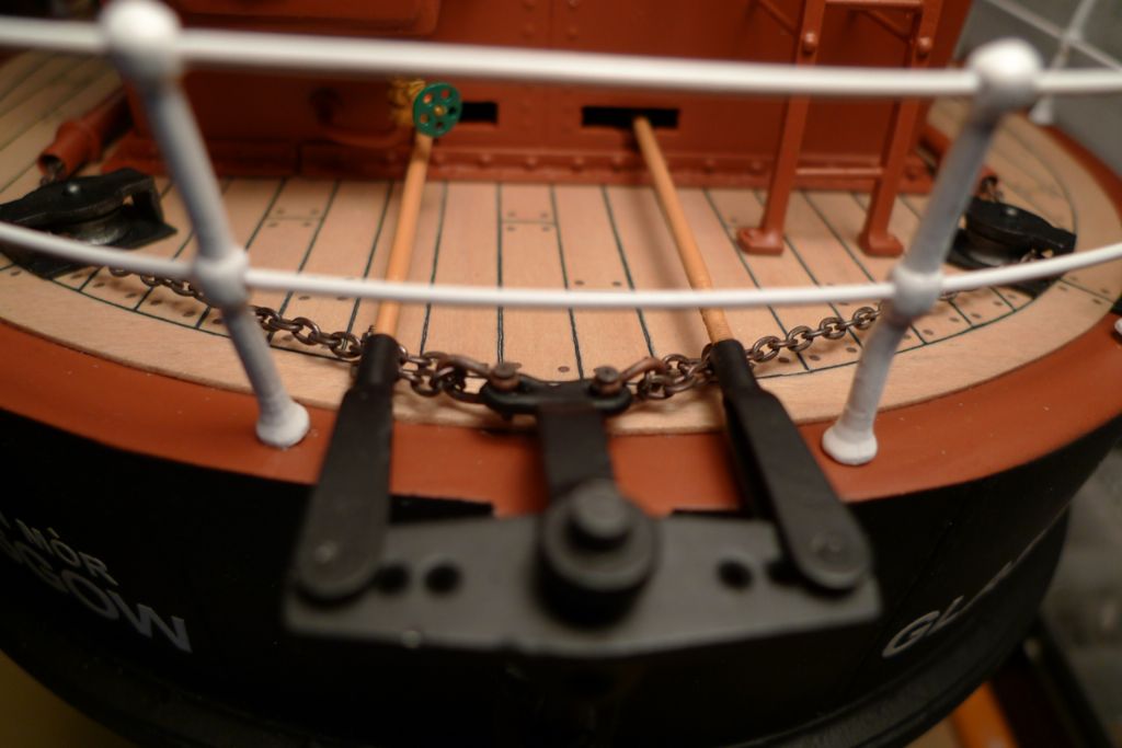
At this stage i also painted and glued down the quartedeck steering chain rollers and chain tubing, added the false tiller and connected up the steering chains to the tiller with some RB Model shackles. The false tiller does not actually move with the rudder, but just sits loosely fitted on top of the rudder post shaft which then moves inside the tiller as the pushrods dictate.
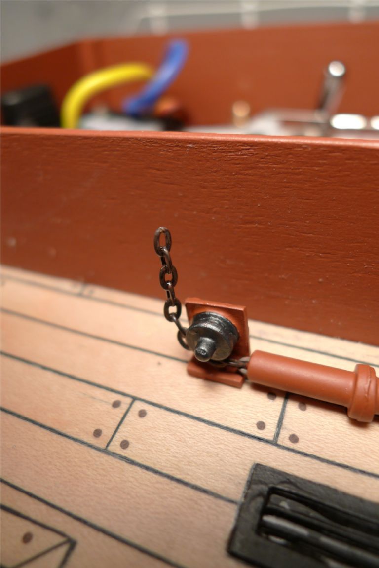
At the other end of the chain tubes, I had to come up with a way of cutting of the chains where they go up towards the top of the engine house, while allowing the tubing on the engine room to fit over them. This was acheived by first fixing the chain ends with thick CA to the rollers where they come out of the tubing, and then glueing the remaining links to each other with several small applications of thin CA so that the ends stand vertically on their own.
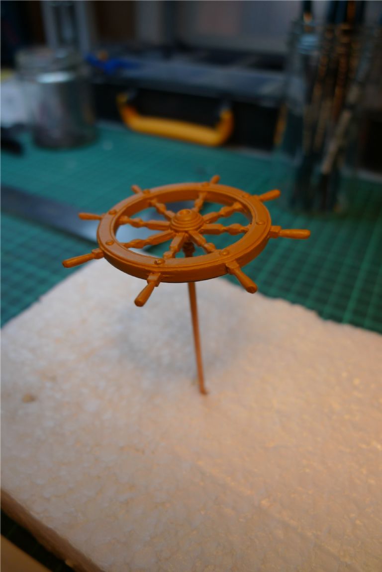
The steering wheel was first given a couple of airbrushed coats of wood brown paint …
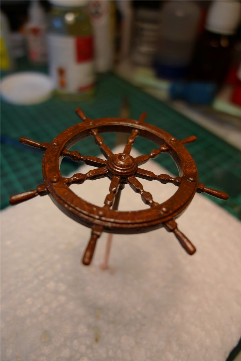
… and then an oil paint imitation graining.
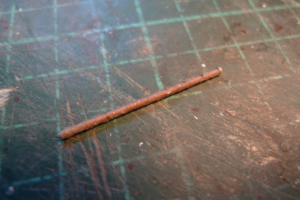
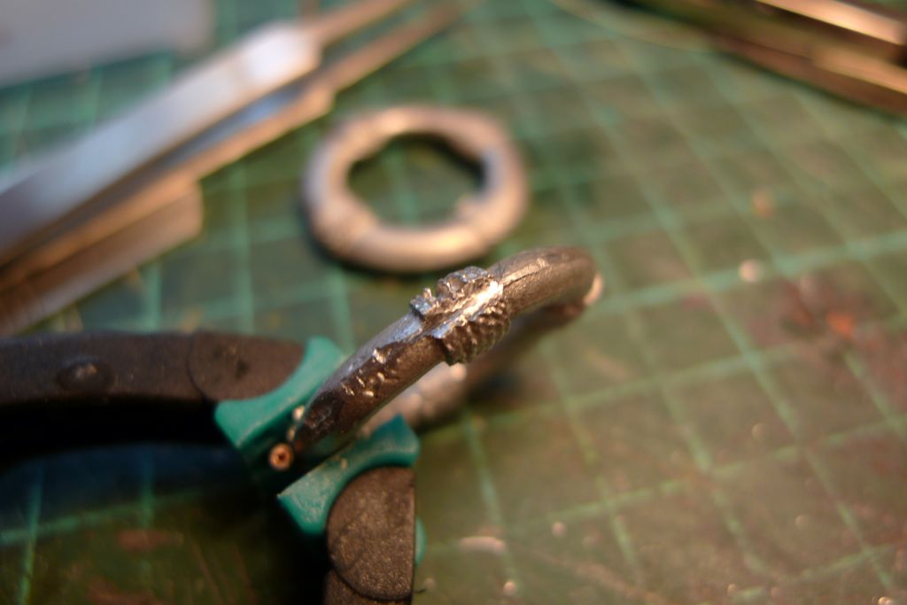
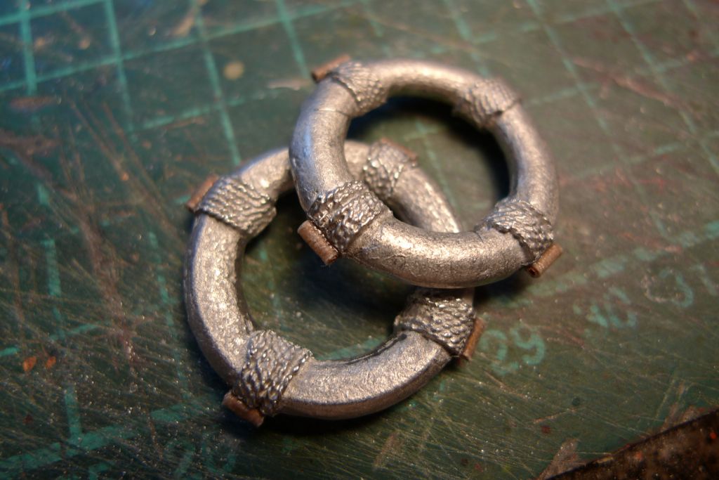
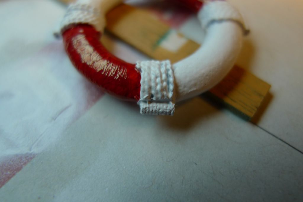
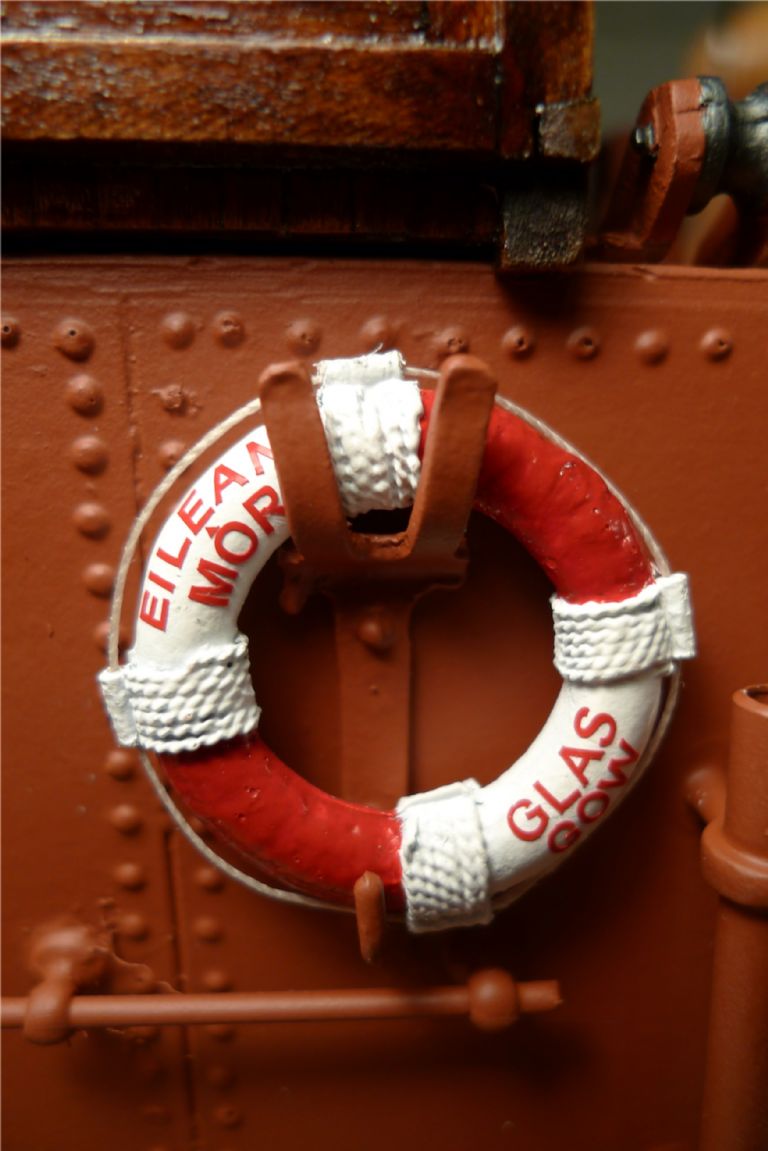
The two white metal life bouys were quite nicely cast, but I still wanted to add the detail of a circumferential grab rope, which would require some apparent means of attachment. As the bouys had cast rope reinforcements at the four cardinal points, I though that the rope attachments ought to look as though they were part of this, and I thus began by serving a piece of 1 mm copper tubing with some 0.10 mm rigging thread which was then liberally drenched in thin CA.
Grooves were filed into the outer edges of the cast rope reinforcements …
… short pieces of the served copper tubing glued into these grooves …
… and the whole thing painted in a classic red-and-white colour scheme.
Finally some 0.25 mm white rigging thread was added, together with 2 mm BECC red lettering spelling out the name of the ship and the port of registry.
To be continued …
/Mattias
Edited By Banjoman on 01/12/2014 12:23:57
2 December 2014 at 08:42 #54042Banjoman
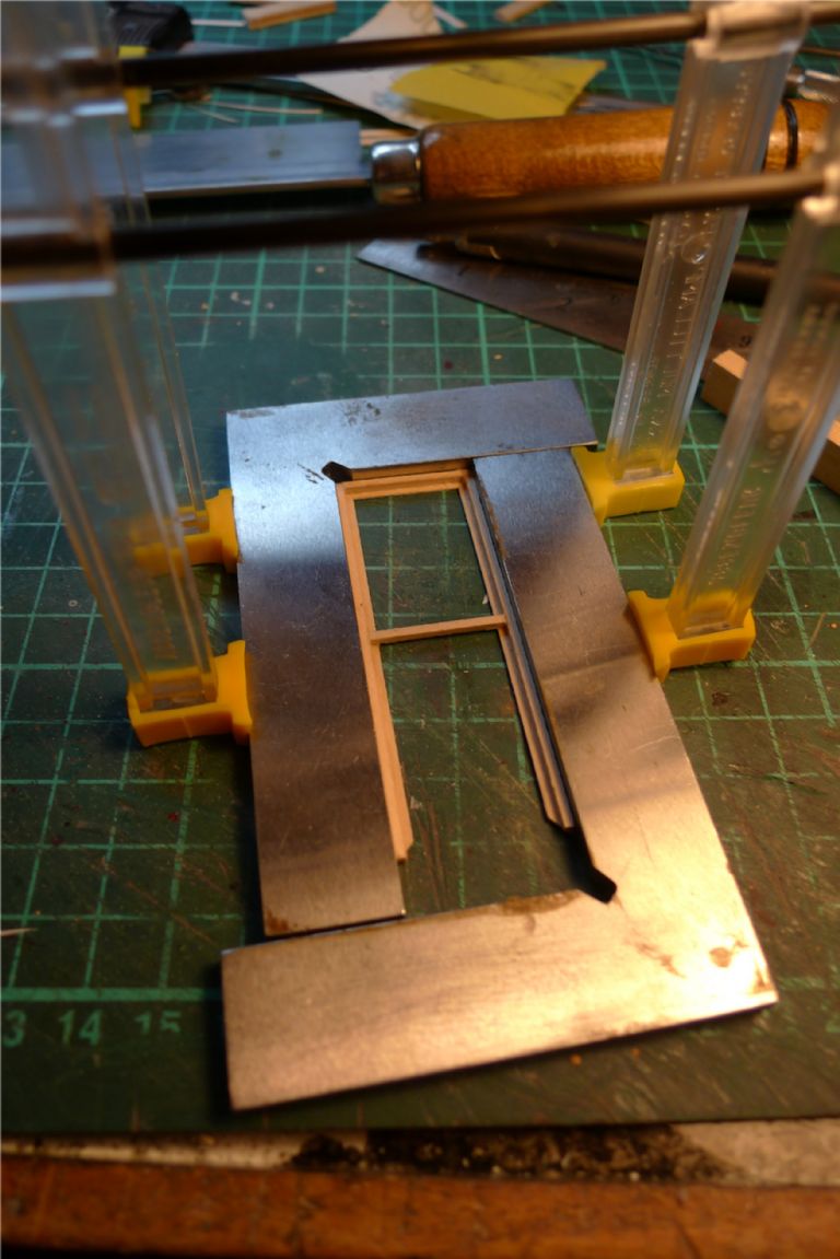
Participant@banjomanWith all the inside panelling done on the wheelhouse, the next job was the door, for which a basic frame was glued together from various dimensions of maple strip …
… to fit the door opening, but without any plywood core, as the door blade had to be thinner than the wheelhouse sides.
The lower half of the door was then filled in with solid panelling made up from 1.5×3 mm maple strip, and the outer framework added.
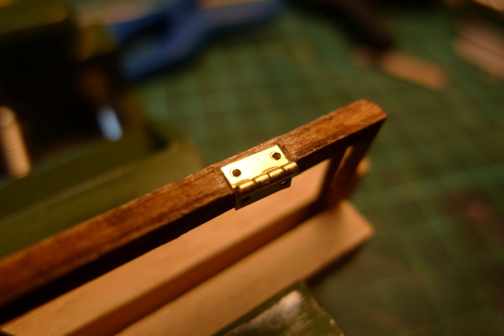
The wood was stained oak and varnished, after which doll's house brass hinges were countersunk into the door and the doorpost …
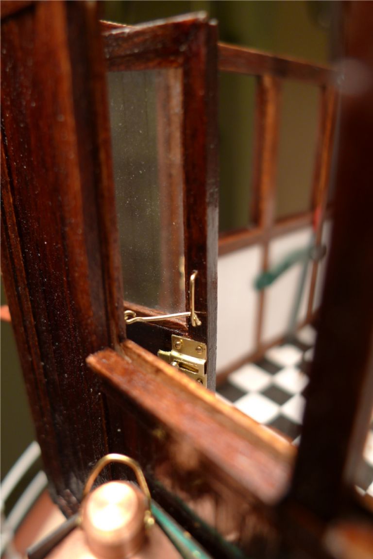
Finally, a brass wire handle and a sliding lock were added on the inside (and a brass know on the outside), with a hasp to hold the door in the open position.
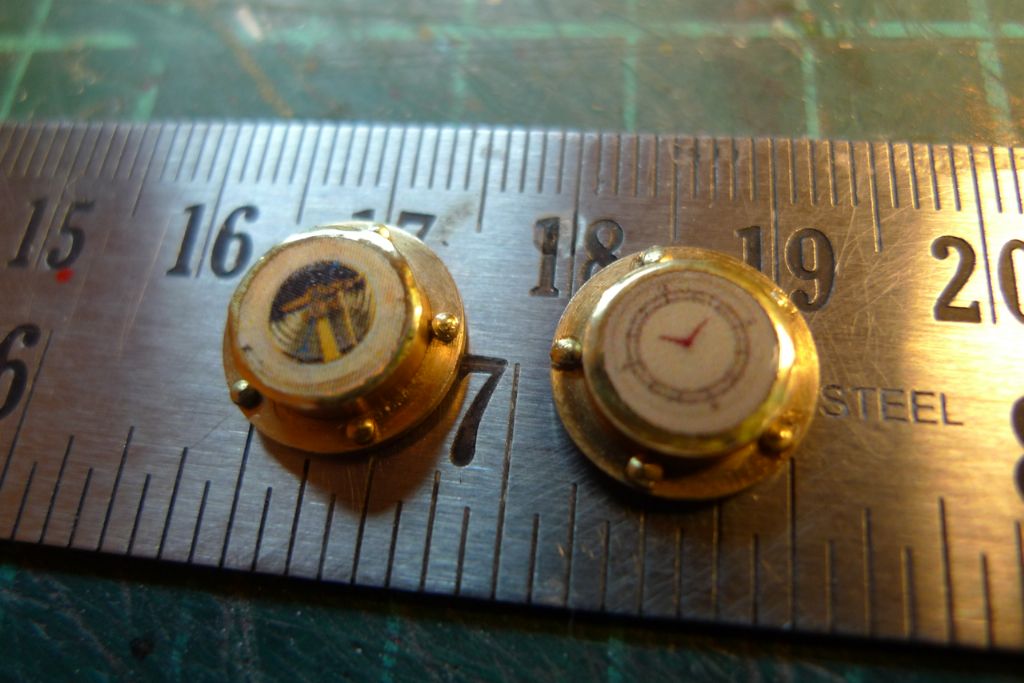
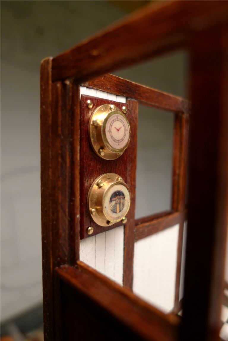
I'd understood fro my reading that Clyde Puffers well into the the 60s and 70s had fairly limited navigational equipment, but I thought that a clock-and-barometer set could reasonably be expected even in 1951, which is the year in which I'd decided to place my build, and thus were made up. For the housings, I used two brass portholes, turned back-to-front, to which were added a BECC decal clock face and a barometer face downloaded from the Internet, over which went BECC bezel decals to give an appearance of brass-edged glass faces.
These were then mounted on a board and hung up in the wheelhouse. The porthole flanges are a bit out of scale, but at a normal distance of observation not disturbingly so, at least not to my mind.
To be continued …
/Mattias
Edited By Banjoman on 02/12/2014 08:42:21
2 December 2014 at 09:02 #54043Bob Abell 2
Participant@bobabell2Hello Banjo
Your modelling skills and attention to fascinating detail is really fantastic and delightfully surprising at times!
You are to be congratulated
Don`t let the lack of comments discourage you, as this is the normal run of things
This model has set the standard of excellence and will be referred to, for many years to come
Well done, Banjo…..Keep up the good work
Bob Abell
2 December 2014 at 09:46 #54045Banjoman
Participant@banjomanI mentioned in my previous post that I'd decided to set this build in 1951. There's no particular reason for it to be that exact year, but for a build like this I like to, as it were, write in my mind a short scenario to guide the build.
I did not want that scenario to be set before (or during) the war, nor too soon after the war either; however, as most puffers were converted to diesel during the second half of the 50s and first half of the 1960s, I was inclined to pick a year sometime in the first half of the 1950s.
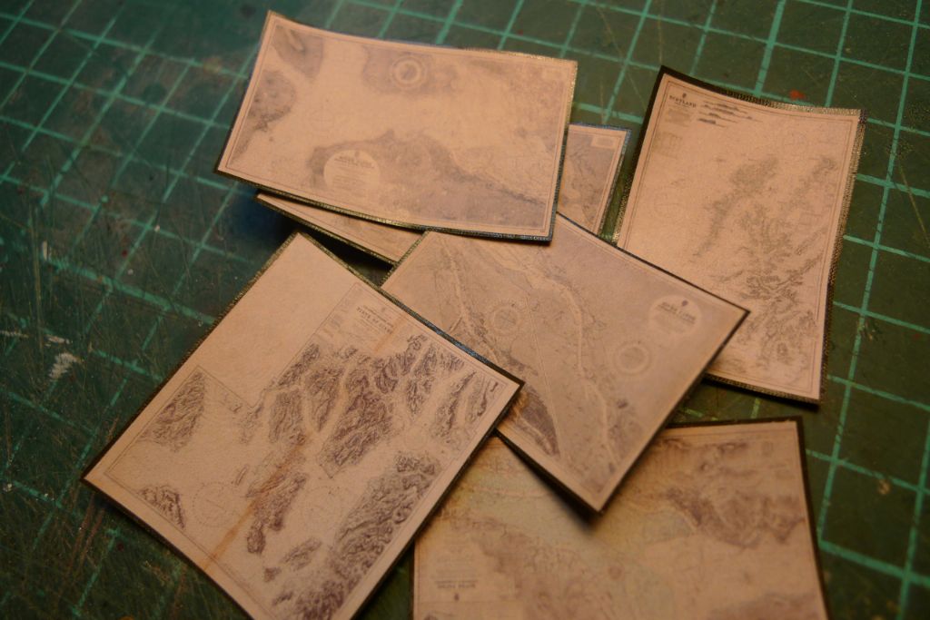
I also wanted to add a chart table and some charts to the wheelhouse. These charts should preferably be as authentic as possible, and I therefore began looking for online sources. These turned out to be more sparse than I had expected, but at the National Library of Scotland I struck a vein of pure gold! They have a fairly extensive collection of old charts of Scottish waters, and also an on-demand scanning service through which one can order full-size, high-resolution TIFF images delivered on DVD of any chart in their collection. There is of course a charge for this service, so I could not just order away, but had to limit myself to a reasonable number of charts.
As I was going to fork out for the pleasure of having these charts, it became important to me that they were the real thing, i.e. from the period and only charts that would have been in use concurrently (as we all know, it is a very strict no-no to go down to the sea in ships using out-of-date charts). Also the charts should be of the West Coast of Scotland in general and the Clyde and Firth of Clyde in particular.
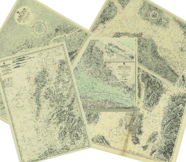
After some e-mail correspondance with the most helpful and friendly staff at the NLS on what was available in their collection, I ordered five charts (two of the river Clyde, two of the Firth of Clyde and one of the whole West Coast of Scotland) that would all have been the latest ones in 1951, which thus gave me the year in which my model is supposedly sailing.
More specifically it is late May or maybe June (= fair chance of good weather, so fine to sail for a bit with the cargo partially exposed), and the Eilean Mòr have sailed from her home port of Glasgow down to Troon, where she has taken on board a cargo of coal for one of the Western Isles (maybe for Mull, or Coll, or perhaps Tiree — it does not really matter). She is now heading up past Arran, and below Bute, bound for Loch Fyne and for the Crinan Canal, and her naughty crew have decided to top up their bunkers (slightly depleted from the journey so far) from the main cargo …
The chart on the wheelhouse chart table is thus the one at the bottom left of the below photo, which shows the part of the Firth of Clyde north of Arran and south of the Cumbraes and of Bute, and the approaches to Loch Fyne. The charts were printed out to scale and given a dark green backing.
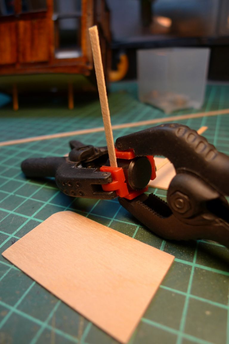
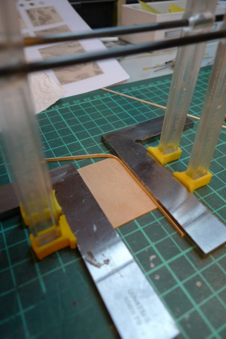
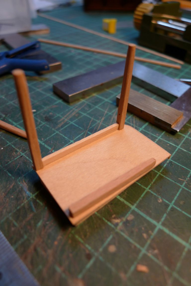
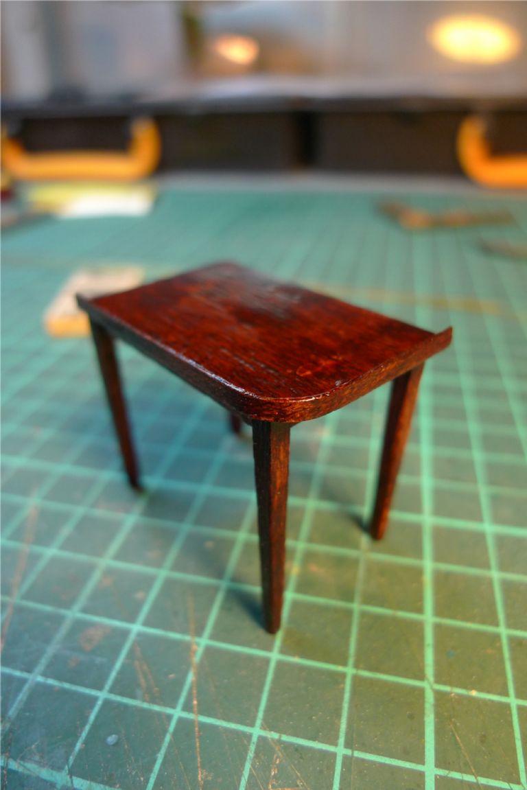
Next up, a chart table was constructed from maple sheet and strip …
… with a fiddle around the outer edge …
… and also legs etc.
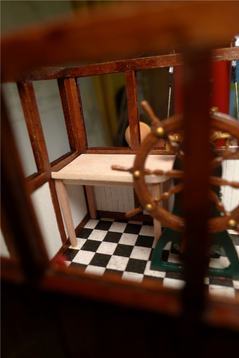
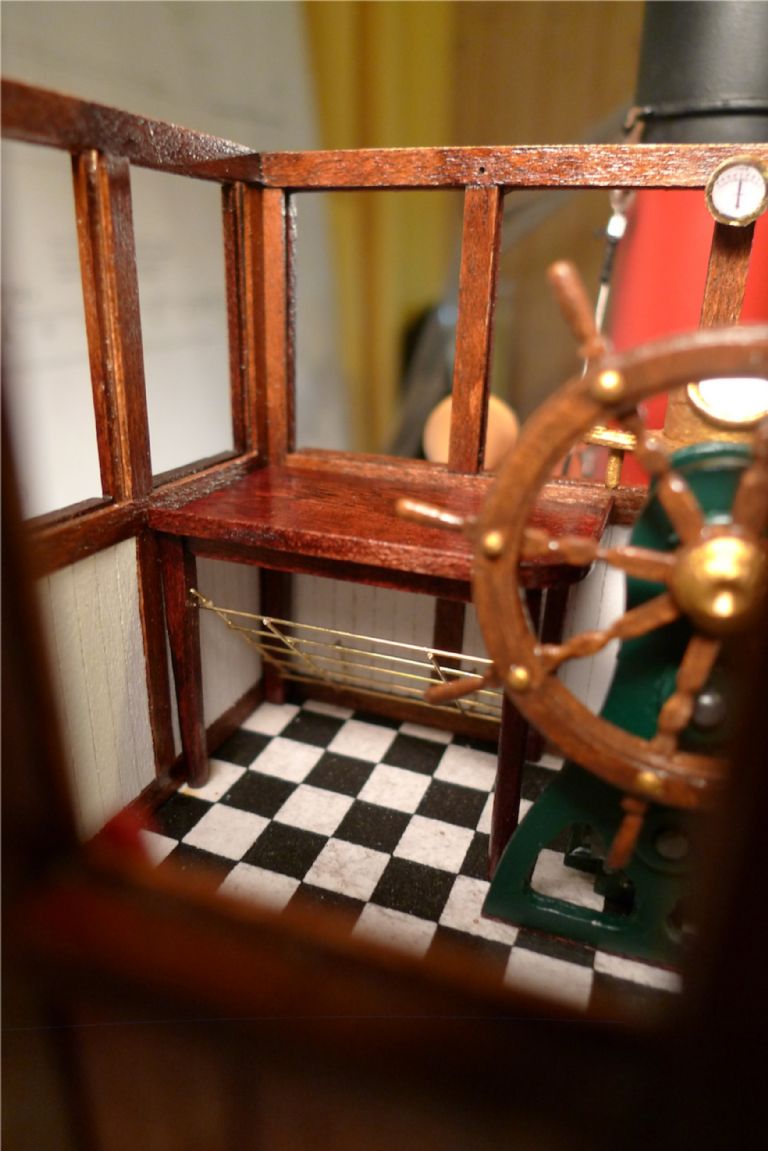
The wheelhouse is not huge, so the table had to be kept fairly small, but is still a tight fit in the port forrard corner.
It was then stained mahaogny and varnished …
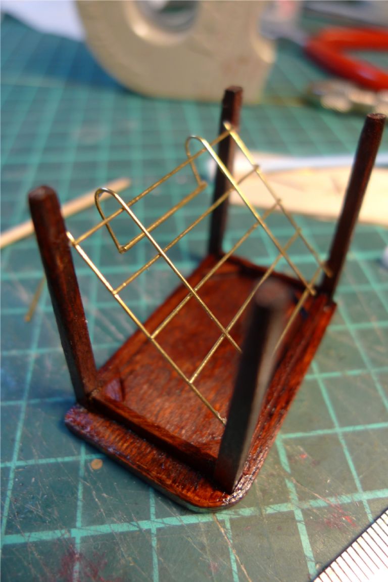
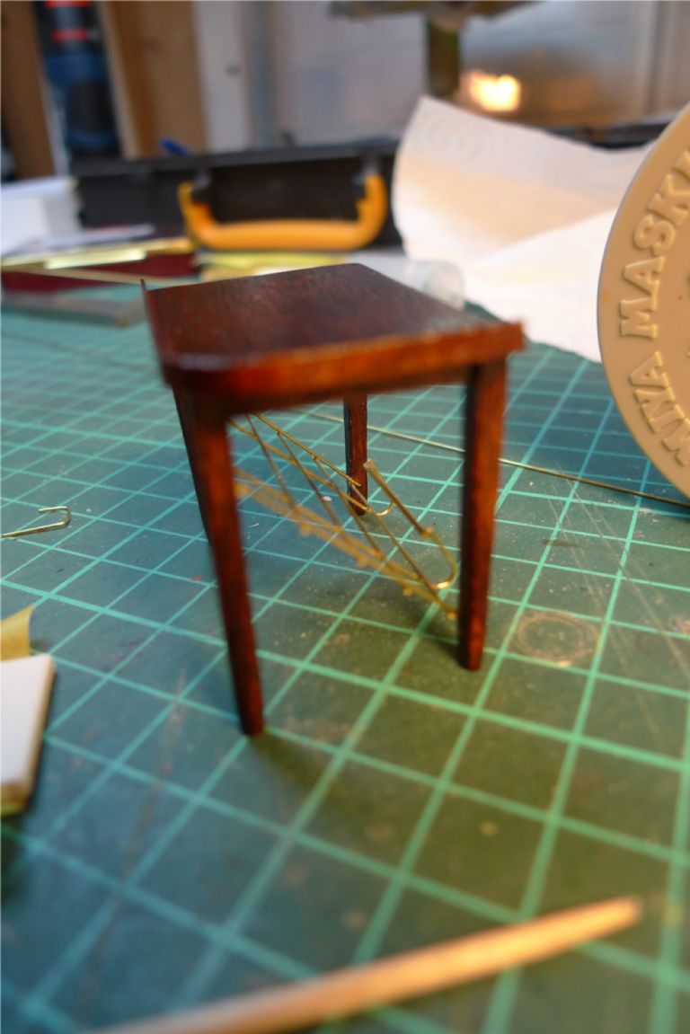
… and had a brass wire shelf added underneath.
A chart drawer would have looked even nicer, but there was little possibility to fit one in, given the limited dimensions available for the table itself, so a shelf had to do for storing a few additional charts.
To be continued …
/Mattias
Edited By Banjoman on 02/12/2014 10:06:42
2 December 2014 at 09:59 #54047Banjoman
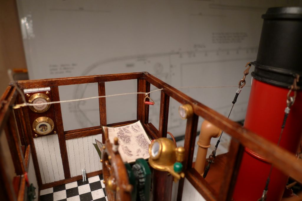
Participant@banjomanHere the table is in place. As can be seen, a clinometer has also been added. It was supposed to go on the binnacle standard, but there it would have been so squeezed in behind the wheel that it would have been impossible to read, and I therefore put it up on the bulkhead instead. A hole has also been drilled in the same bulkhead for the steam whistle pull to go through.
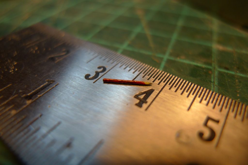
To add a few more details to the chart table, I also made a pencil by taking a short (8 mm) length of 0.7 mm propelling pencil lead, sanding it hexagonal, putting a point on one end and then smply painting it red with a pale yellow taper towards the unpainted point. In other words, it is actually a fully working 1:24 scale pencil …

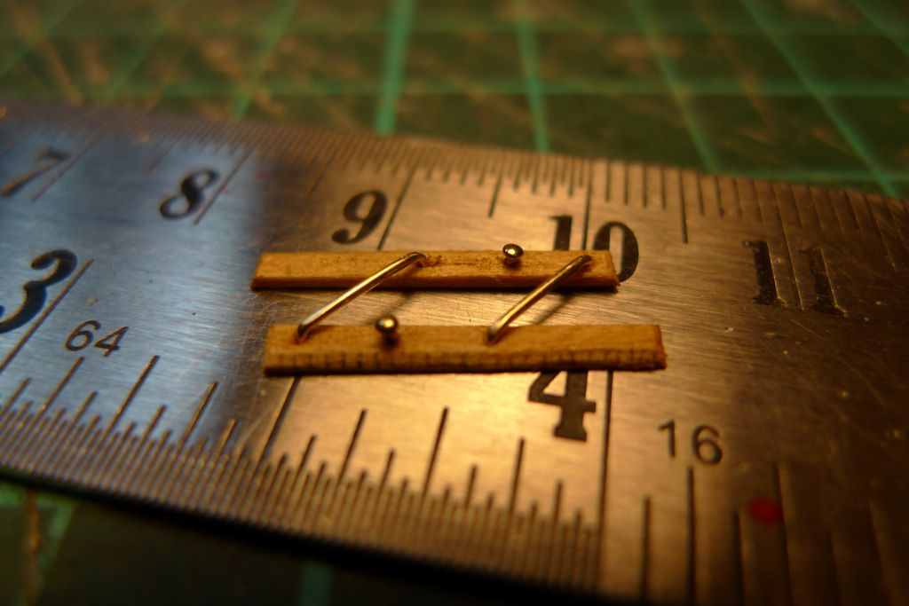
I also made up a set of parallell rulers …
… and added the steam whistle pull, with a handle made from turned wood,painted red, and some brass wire.
The careful observer will also notice the two thin wires, painted white, that come out of the side and go down through the floor. These are of course the leads for the port navigation light.
On the matter of the navigation lights, I have had to compromise a wee bit with complete realism. From what I understand it was rather uncommon even up through the 1960s for ships like these to be electrified, and the navigation lights therefore ought to have been oil lamps. However, as I wanted to have working running lights, and it would be quite difficult to get an electric wire up to the mast top light (which is not attached to the mast, but flown from a short outrigger) without it being visible, I decided to bite the bullet instead, and to say that this partciular ship had a very enlightened (ha!) owner who had had her at least partially electrified.
However, even though uncommon, I did read somewhere that I was not completely unheard of either, and I therefore did not bother to try to hide the wiring inside the wheelhouse either, but just painted it white as might have been done in real life, too.
The one way I could think of to bring discrete electricity up to the mast top light would have been to use very thin (0.10 or 0.15 mm) enamelled wire, and then to try to thread this through a length of rigging thread made to represent the lantern downhaul, but in the end I decided not to, as I felt that it would have been too prone to breakage, nor were I certain enough that it would stand up to the currents involved.
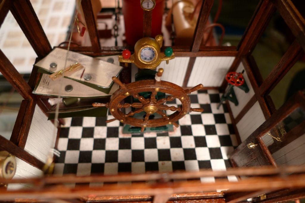
Finally a few lead chart weights were made by simply flattening some lead shot, and the whole shebang dryfitted. As can be seen in these photos, the steering wheel has also had a few brass paint touch-ups, and the center spoke marked with a brass end and a few turns of rigging thread.
To be continued …
/Mattias
Edited By Banjoman on 02/12/2014 10:03:20
2 December 2014 at 13:06 #54048Gareth Jones
Participant@garethjones79649Hi Mattias
I think you are making a wonderful job of this model, the attention to detail is outstanding and the quality of the build is fantastic. Not only that but the photos you are using to illustrate progress are also excellent. Please keep it up, you will be a very hard act to follow.
If you could bring the model to the Model Boat Convention at Haydock Park in the UK next August I am sure you would be in line for the best Mountfleet Model Trophy.
Regards
Gareth
2 December 2014 at 15:14 #54052Banjoman
Participant@banjomanHello Bob and Gareth,
Warmest thanks to you both for your way too kind words — 'tis blushing I am to be eulogised like that by past masters like you two gentlemen — praise from you is praise indeed!
I had a quick look at the Model Boat Convention website, and I must say it looks like it would be both huge fun and extremely interesting, although I must as yet refrain from making any over-enthusiastic commitments in that direction. It would be a bit of a trek from Belgium (albeit perfectly feasible) and it very much remains to be seen what next years holiday planning entails. As a matter of fact I have already been thoroughly spoilt that way by my dear wife, as she has agreed for us to go on a five-day cruise on the VIC32 for my 50th birthday next May … something I dare say you can imagine that I'm rather looking forward to …

Again, thank you very much indeed!
/Mattias
Edited By Banjoman on 02/12/2014 15:15:12
2 December 2014 at 17:56 #54057 Colin BishopModerator@colinbishop34627
I have to agree with Gareth, I'm sure you would enjoy the Haydock Park event. Belgium isn't so far away, last September my Wife and I drove down to the Ardennes via Bruges for a very enjoyable short break!
Colin
3 December 2014 at 09:10 #54067Banjoman
Participant@banjomanThanks, Colin! It is indeed not that far; however, even going straight there would take about eight to ten hours either way, including ferry and pit stops, and thus would require minimum one or two days of leave around the weekend … Remains to be seen, thus, but yes: the thought has been planted …

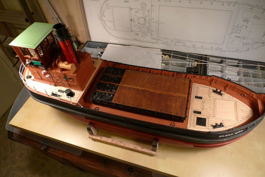
Anyway, back to the build! The ship now (i.e. back in mid-June) looked like this:
The wheelhouse was pretty much finished now, apart from the windows (which I decided to leave for more or less last, in order not to unnecessarilly risk brekaing them during the further build) and the roof, so putting a rroof together was next on the programme.
I wanted to make the roof removable to maintain access to the wheelhouse interior, both for further work, for a better view and to facilitate any future repairs or additional detailing.
To this end, I cut out two transversal beam cores from 1.5 mm plywood, with a slight camber on top to give a curved roof line, and with shallow tabs fitting down into the tops of the wheelhouse window slots. These were then joined with shorter, longitudinal beams …
… after which the transversal beams were covered on the in- and outside with some maple strip to make their edges flush with the wheelhouse fore and aft sides. the whole frame was then sanded down and a 1 mm plywood roof was glued on. This, too had, been given that same slight lozenge shape into which I had had to twist the whole wheelhouse structure …
… as was the piece of 0.5 mm maple sheet that went on top of the plywood to create a more varied set of lines on the roof.
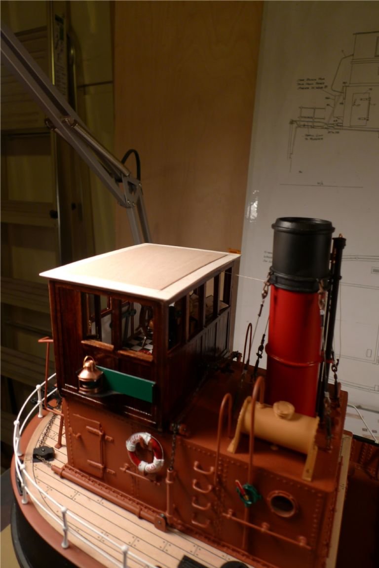
The inside beam edges were then panelled in such a way as to create an edge sticking down and covering the top mm or so of the wheelhouse side insides, after which the roof itself was painted oxide green with my own mix of Vallejor Premium RC colours to the following recipe: 1×62.013 (Basic Green), 2×62.014 (Dark Green), 7×62.015 (Yellow Ochre), 10×62.019 (Grey) and 10×62.001 (White). The roof beams were stained oak and varnished, and finally the ceiling was panelled in maple strip painted white, similar to the interior side panels.
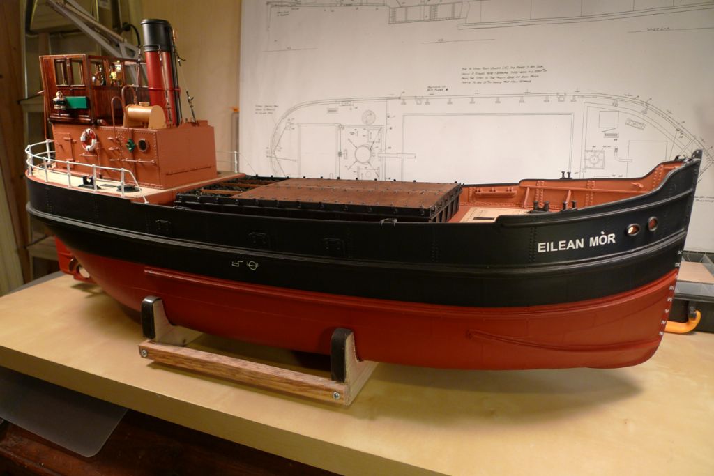
With the roof in place the ship now looked like this:
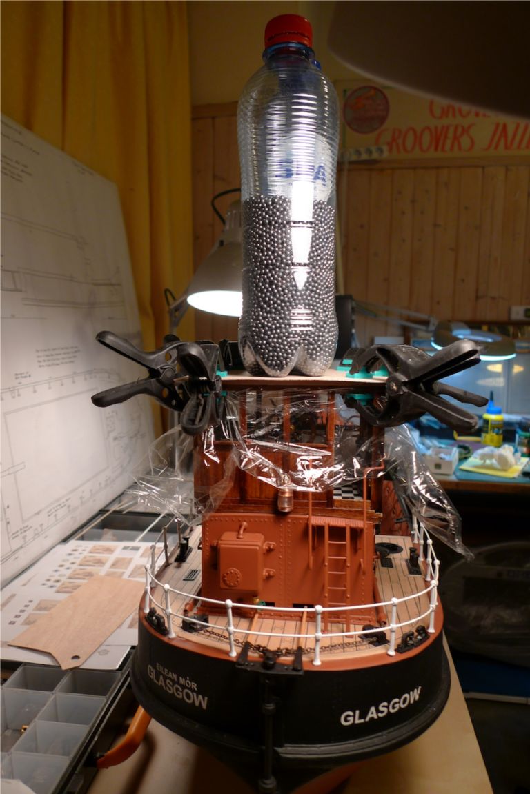
As already discussed in anoher tread, I then recently completed the roof installation by adding magnets in the corner posts …
… and steel nail heads in the correponding corners of the roof itself.
Concurrently with constructing the roof I also completed and mounted the rear light …
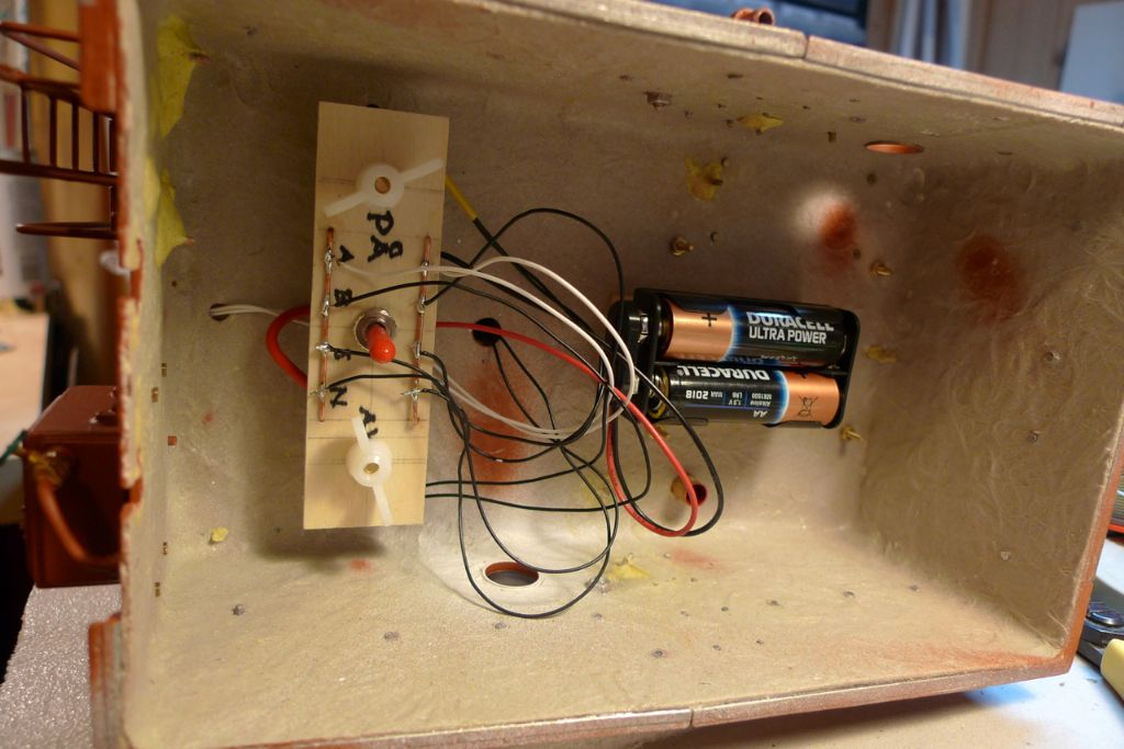
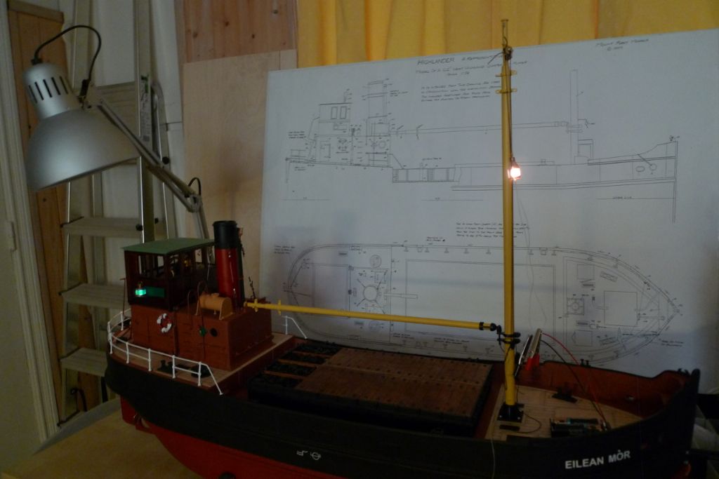
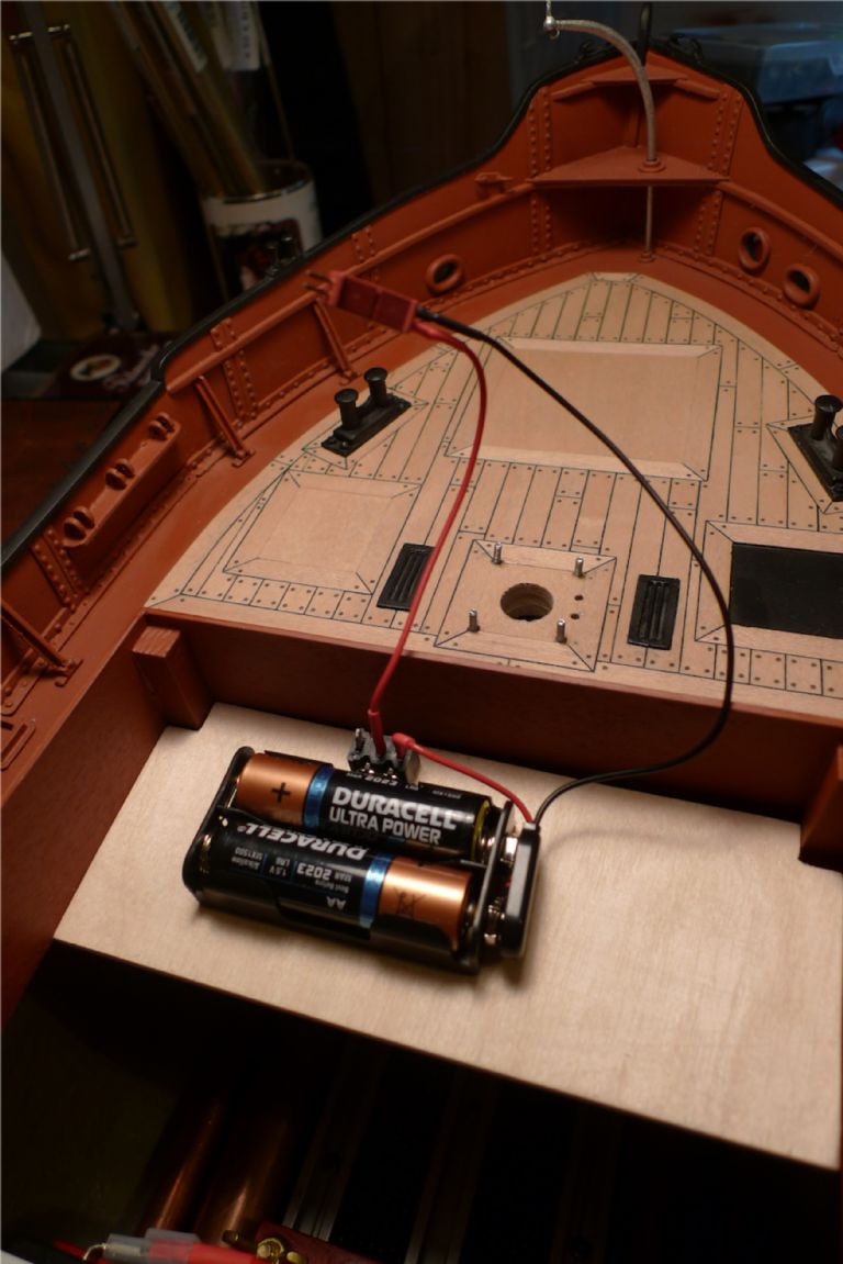
… and connected up the wheelhouse lights (all 3V grain-of-wheat bulbs) to a simple circuit board made from a piece of plywood with some 1 mm copper tube serving as connector between a pack of two AA batteries and the lights, connected in parallell and equipped with a simple, manual on-off toggle switch.
I decided not to use a r/c switch, because (a) turning on the lights will only really be relevant if ever I go sailing at dusk or at night, (b) when making the boat ready to sail I willl in any case always have to lift of the engine room to get at the main and r/c on/off switches, and (c) in this way, there's no need for any "umbilical cord" between the superstructure and the hull that would have to be either rather long or separated and reconnected every time the structure went off or on.
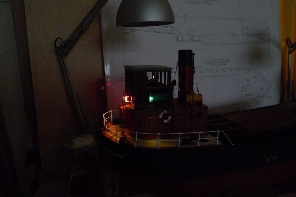
With the workshop lights turned off, this is what the ship's lights looked like:
To be continued …
/Mattias
Edited By Banjoman on 03/12/2014 09:11:49
Edited By Banjoman on 03/12/2014 09:12:02
Edited By Banjoman on 03/12/2014 09:12:20
Edited By Banjoman on 03/12/2014 09:13:00
Edited By Banjoman on 03/12/2014 09:16:47
3 December 2014 at 11:50 #54068Dave Milbourn
Participant@davemilbourn48782What a superb build. I'm not only envious of your building skills and attention to detail but I wish I too was looking forward to my 50th birthday…………….. instead of my 21st for the third time round! 1951 was a good year, it seems.
Dave M
5 December 2014 at 10:44 #54113Banjoman
Participant@banjomanThank you ever so much, Dave — and yes, speaking of the good year 1951 I've spent a number of hours over the last few days doing a (rough-and-ready) transcription of the March 22nd 1951 recording by the Crane River Jazz Band of Dauphin Street Blues … which, of course, my Puffer crew could have been listening to if they had maybe a wind-up phonograph in fo'c'sle, and were trad fans … which I suppose would not have been too implausible in 1951?! And of course provided that that particular recording had also been released by Spring/early summer!
Anyway, the next job tackled on the build was the mast and boom.
The mast surround was made up of three white metal castings, and would have to be drilled out to take the 12 mm dowel from which the main part of the mast was to be made.
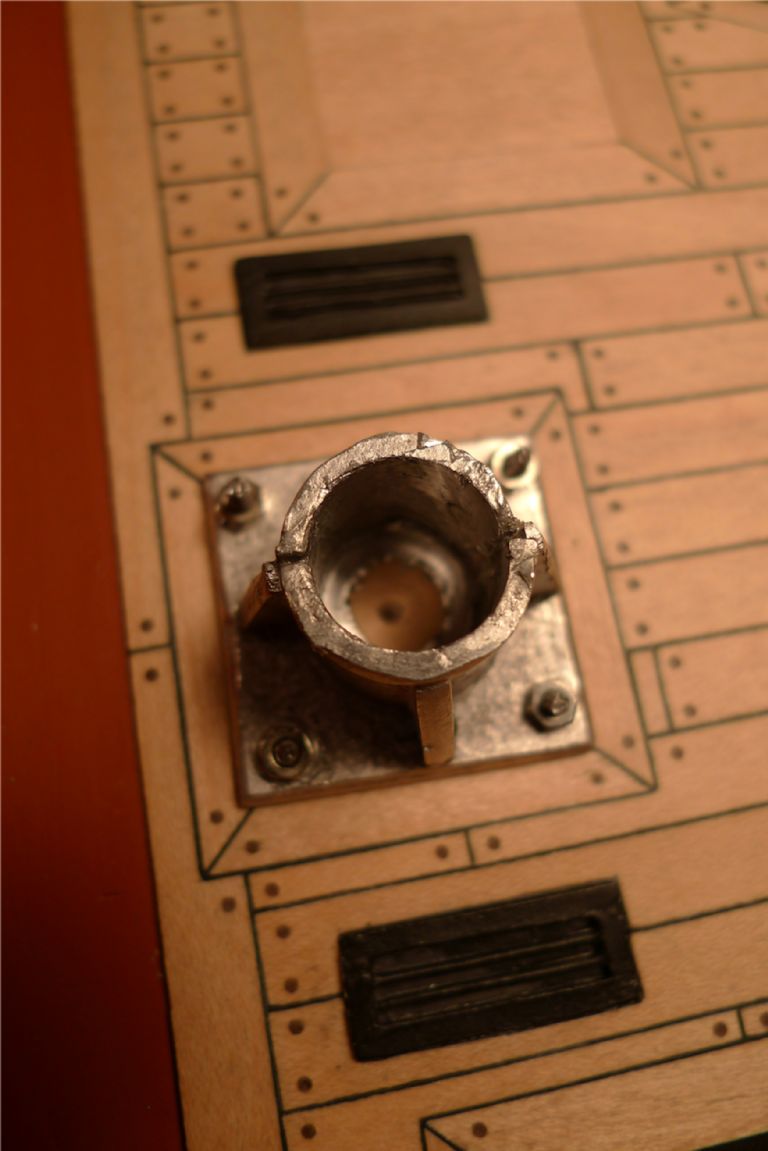
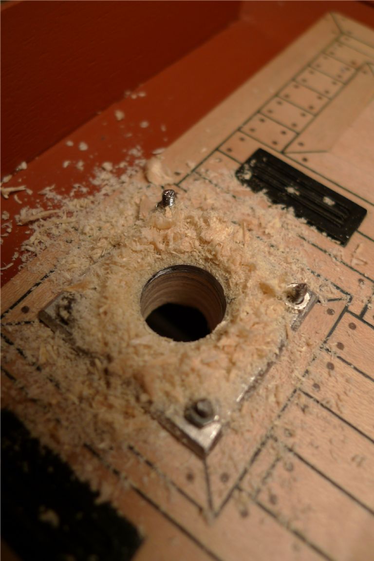
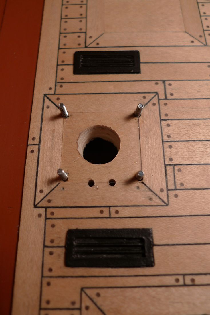
To make sure that this drilling out lined up perfectly with the hole that would have to go through the deck, I decided to do the job in one go and in situ. I therefore first glued together the mast surround assembly, carefully positioned it on the deck planking underframe, marked out the four corner bolt holes on the deck and drilled four 2 mm holes through the deck. The mast surround could then be bolted down with M2 bolts and nuts, a center unch used to mark the center of the mast hole …
… and the main 12 mm hole drilled through using a small cordless 10,8V drill/driver, which I find an extremely useful complement to the sometimes too small and weak Dremel-type tool and the somehwat large and cumbersome full-size power drill.
The mast surround flanges actually came off again during this process, as part of the glue joint was drilled away, but this was foreseen and not a problem, as it was easy enough afterwards to put it back together again. The resulting hole was then smoothed down and slightly enlarged with a sanding drum in the Dremel, to make sure tha mast would still fit through after painting.
I had early on decided not to fix the mast permanently, i.e. not glue it in, to make sure that it could be removed if needed for transport or storage, but also to make its rake and list adjustable.
As the foot of the mast sits some 120 mm or so below, and the mast the rises to +/- 450 mm above deck level, there is roughly a 1:4 gearing between foot and top, i.e. moving the foot 1 mm in any direction moves the top +/- 4 mm the opposite way.
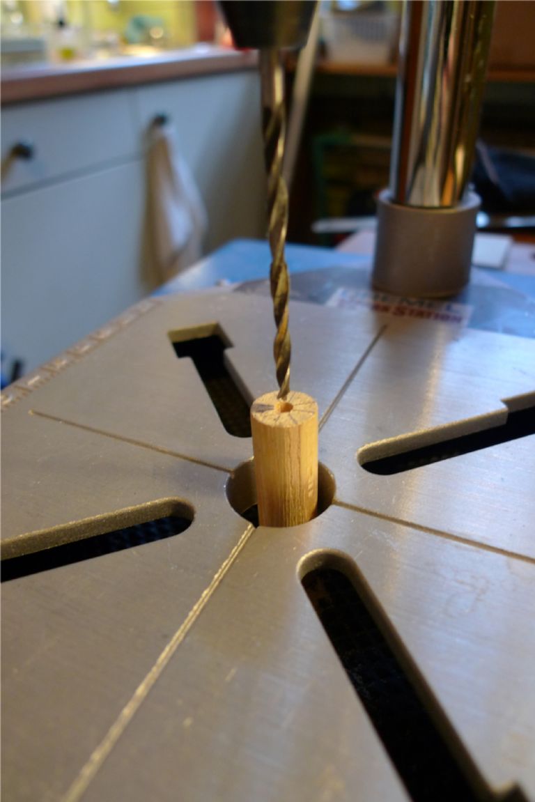
I first centre drilled a 3 mm hole into the foot of the mast dowel blank.
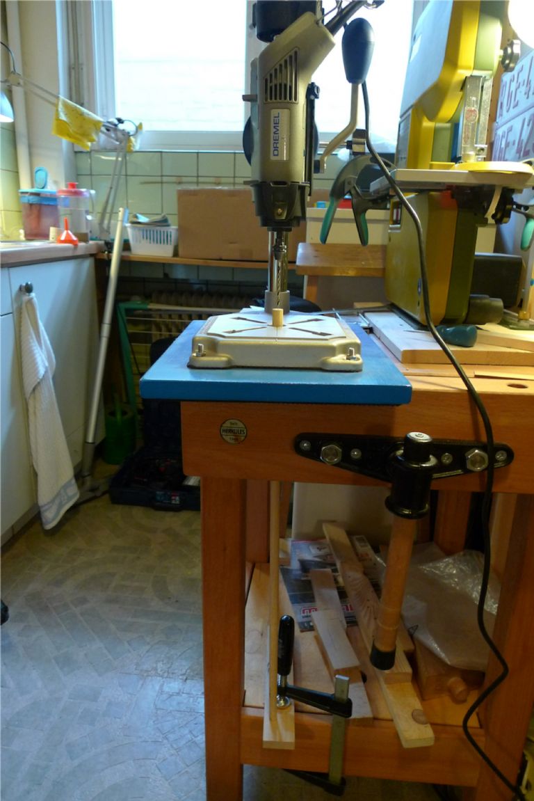
In order to accomodate a good half a metre of dowel into my Dremel drill press, I first had to drill a hole through the drill press base board, then used the bench vise to hold the dowel in place and simply sat the drill press down around the protruding dowel end. To make sure that the dowel would not slide downwards under the pressure of the drill, a short length of wood was clamped to the lower shelf of the bench for the other end of the dowel to rest upon. The jaws of the vise were tall enough to ensure a good enough plumb line on one axis, and with a water pass the other axis was easily set to a straight enough vertical.
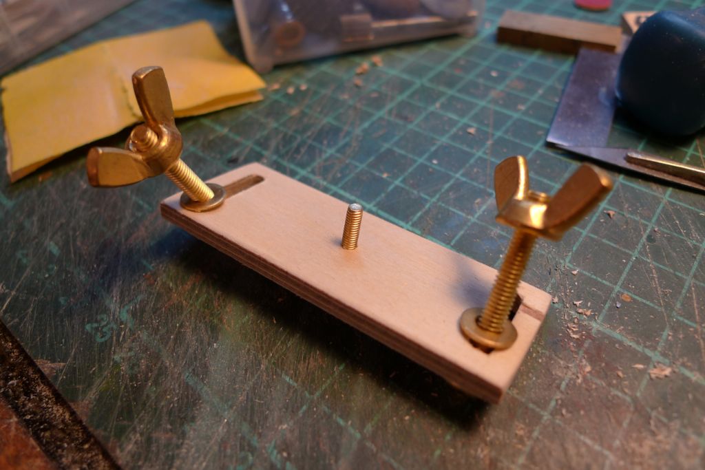
I then made up a small adjustable mast foot board, with a centered M3 screw to go in the hole at the base of the mast, and two M4 clamping screws set into grooves at the end so that the board could be clamped to the center rail of the rail system at the bottom of the hull.
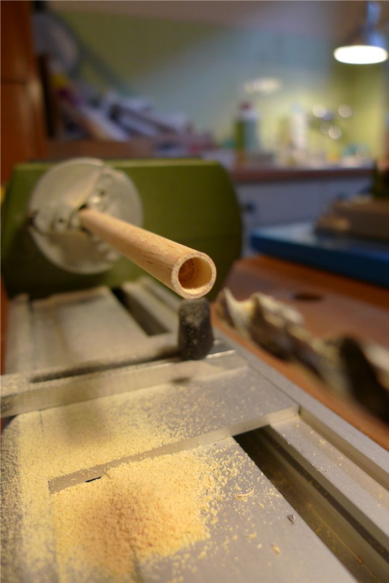
Both the mast and the boom needed smaller diameter dowel end pieces, for which the mast and boom blanks had to be centre drilled. The boom blank fitted nicely into the micro lathe, and could be drilled out there using a fixed (i.e. non-turning) drill chuck in the tailstock …
… and the lathe then also came in very handy for turning the end of the boom to a taper towards the end piece (which here is rather longer than the finished thing, as it has not yet been cut to final length).
To be continued …
/Mattias
Edited By Banjoman on 05/12/2014 10:49:24
5 December 2014 at 10:45 #54114Banjoman
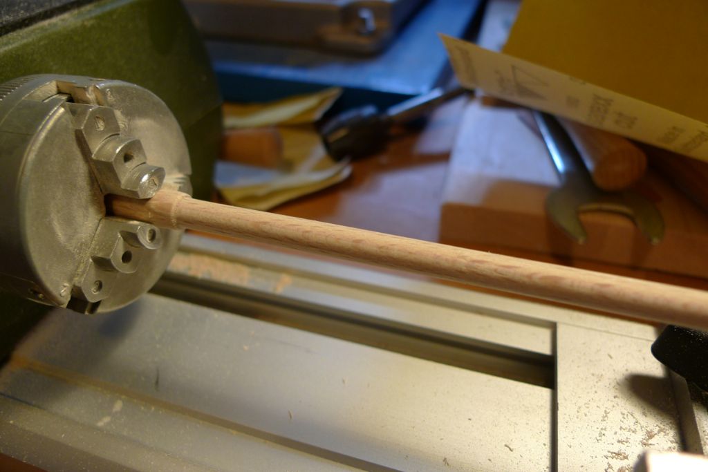
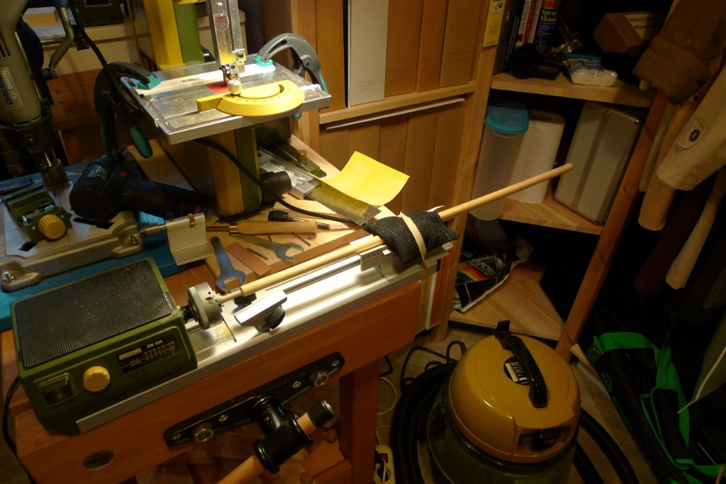
Participant@banjomanThe mast assembly likewise needed to be turned to a taper just below the joint between the main mast and the top piece. However, the 12 mm main mast dowel would not fit through the lathe (max fit-through diametre is 10 mm), so I instead hit upon the idea of using the cradle accessory instead of the tailstock. The top piece, only 8 mm in diametre, could then be secured in the chuck and the mast rested in the cradle.
As the free end was much heavier than the fixed end in this arrangement, if the lathe were just turned on the free end would first wobble and then start whipping around until something most likely broke. I therefore laid a 0.5 kilo bag of lead shot on top of the cradle, and loosely secured it in place with a large rubber band. This very effectively allowed the mast to rotate in the lathe without the end going out of control. Obviously the set-up is a bit Heath-Robinson, and would not withstand too much force, but it did the trick here, and the taper was succesfully turned …
.. resulting in a derrick assembly that looked like this with its main white metal fittings dry fitted.
To be continued …
/Mattias
Edited By Banjoman on 05/12/2014 10:50:50
5 December 2014 at 10:58 #54115Banjoman
Participant@banjomanOh, and for those who might share my taste in music, the Crane River Jazz Band recording mentioned earlier can be found on YouTube (**LINK**), although the chap who put it up there must have taken it off the original 78 rpm with the record player running at the wrong speed as the song was recorded in B flat but here plays at A natural (minus a further 10 percent or so below A=440).
The recording can also be bought from iTunes, though, and there it plays at the correct speed

/Mattias, going (mildly
 ) off-topic …
Edited By Banjoman on 05/12/2014 10:58:34
5 December 2014 at 14:25 #54118Banjoman
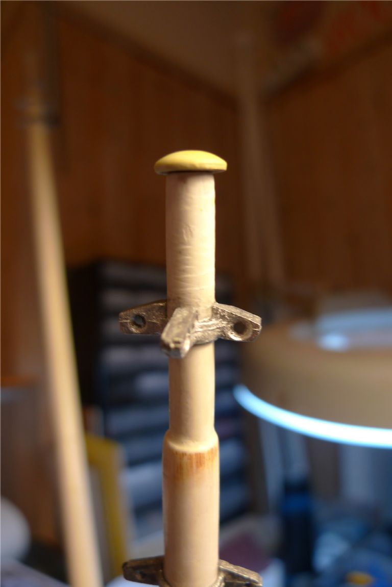
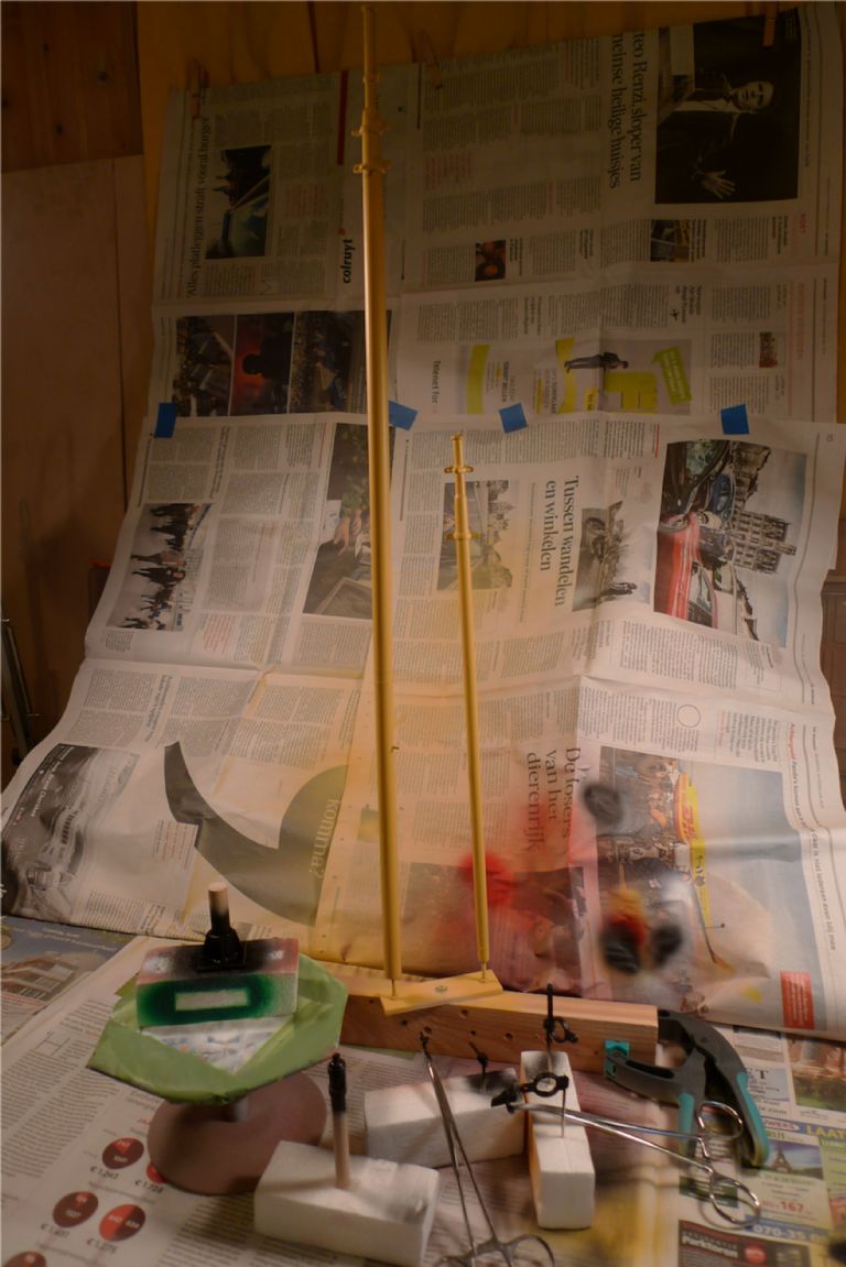
Participant@banjomanAfter giving mast and boom the usual filler plus sanding filler treatment, tose fittings that were going to be painted in the same colour as the mast and boom were glued in place, and caps fashioned for the boom end and mast top. Suitable size washers were glued to the spar ends, and a rounded cap created from a dab of Miliput, quite smply by applying a circular movement with a wet finger top.
The spars where then painted a pale yellow, and the remaining fittings black.
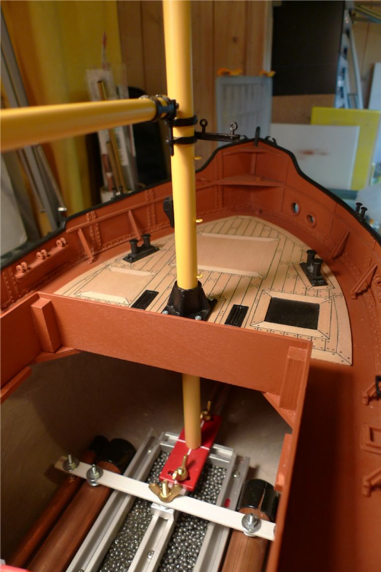
The next photo shows the mast angle adjuster down in the keelson: by sliding it back and forth along the rail, the rake can be adjusted while a sideways movement along the athwartship grooves will adjust the lateral tilt. When one is happy with oth rake and tilt, the adjuster can be clamped in position by tightening the wing nuts, and the mast stepped and unstepped in exactly the same position as often (or not) as one wishes.
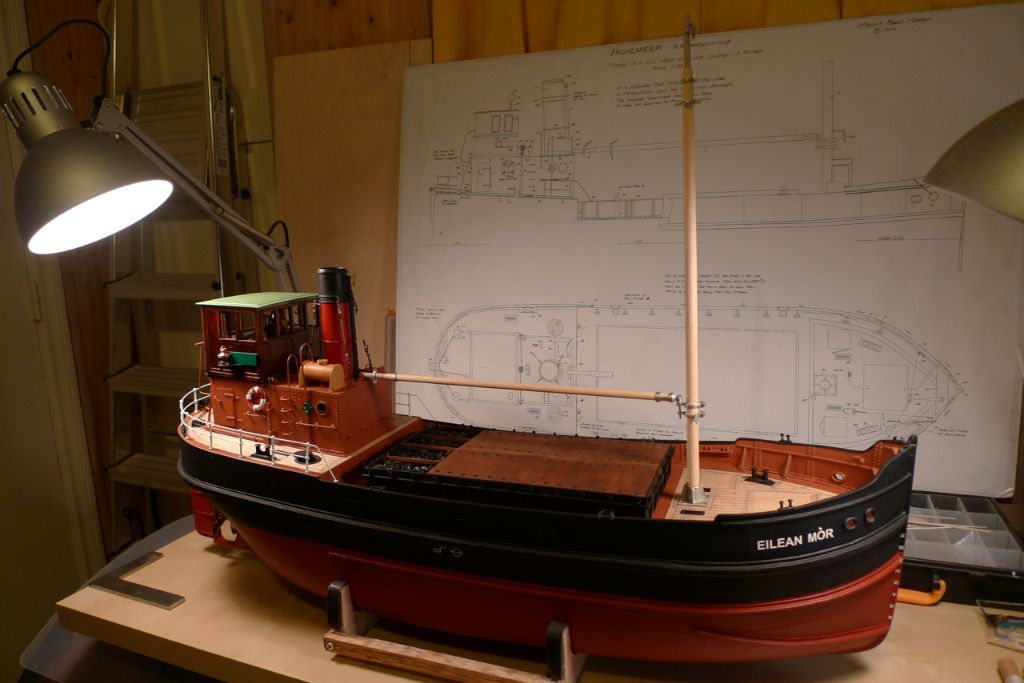
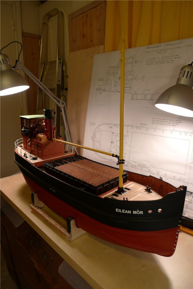
Finally an overview picture of the build as it then stood.
To be continued …
/Mattias
6 December 2014 at 16:41 #54133IAN_I
Participant@ian_iHi Mattias…
The detail on your build is second to non….amazing work.
Regards,
Ian
6 December 2014 at 22:51 #54149Banjoman
Participant@banjomanThank you very much indeed, Ian, for your kind words!
After basic work on the mast and boom had been finished, and before I moved on to tackle the winch, a few smaller jobs were interspersed.
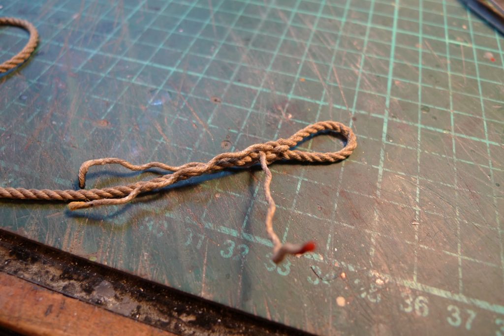
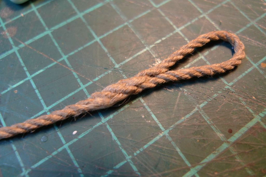
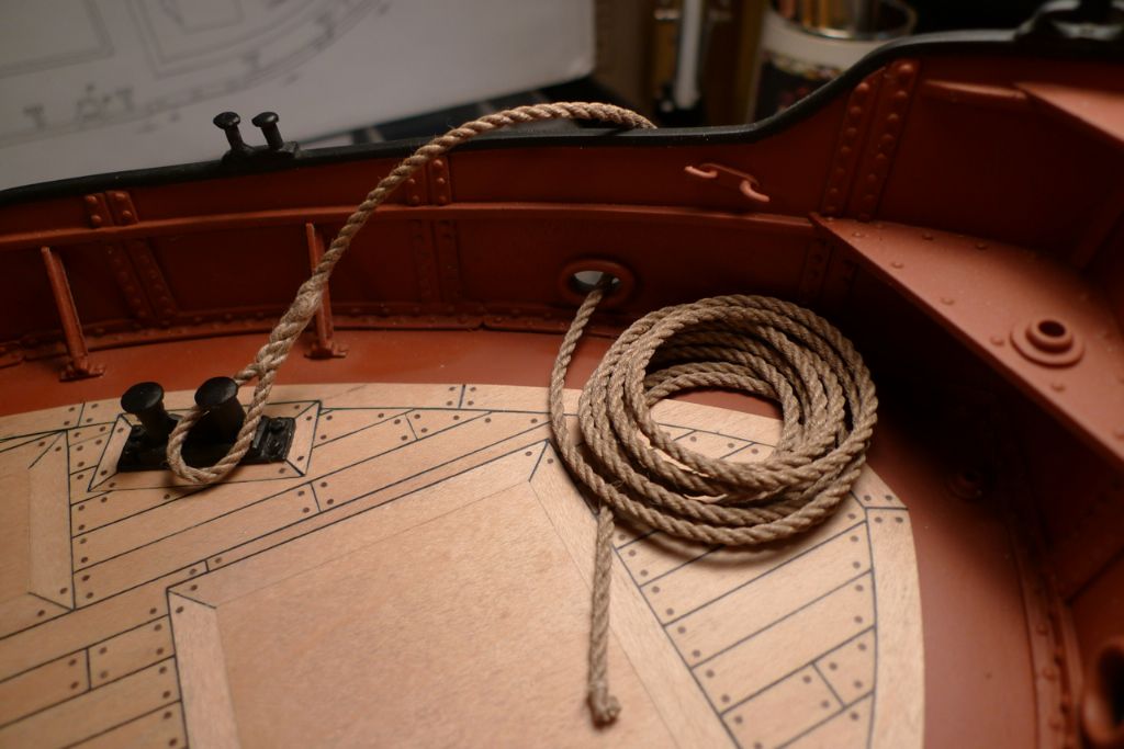
I'd gotten hold of some lovely 2.5 mm rope, beautifully handmade from flax and sold by Eskader in Stockholm, that I thought would make a great mooring cable. As the rope was so well laid, I decided to have a go (for the first time in my life) at making an eye splice in one end …
… and ended up with the following result …
… that I must say I think looks rather nice on board the ship!

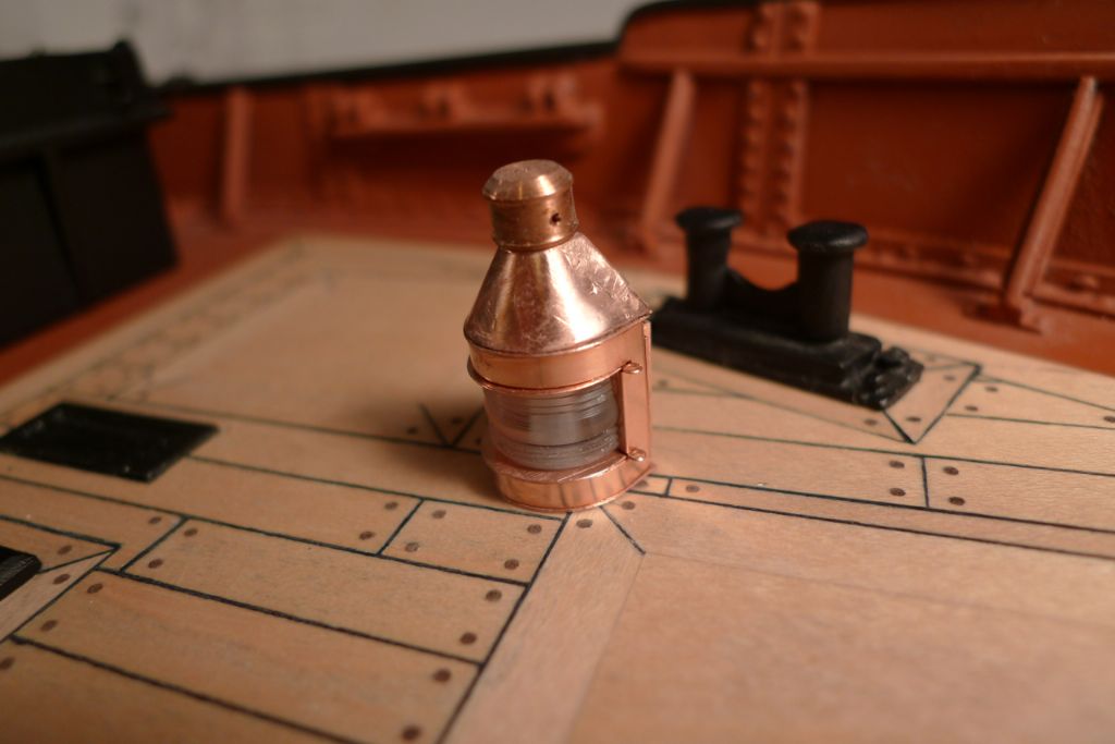
I also put together the top light …
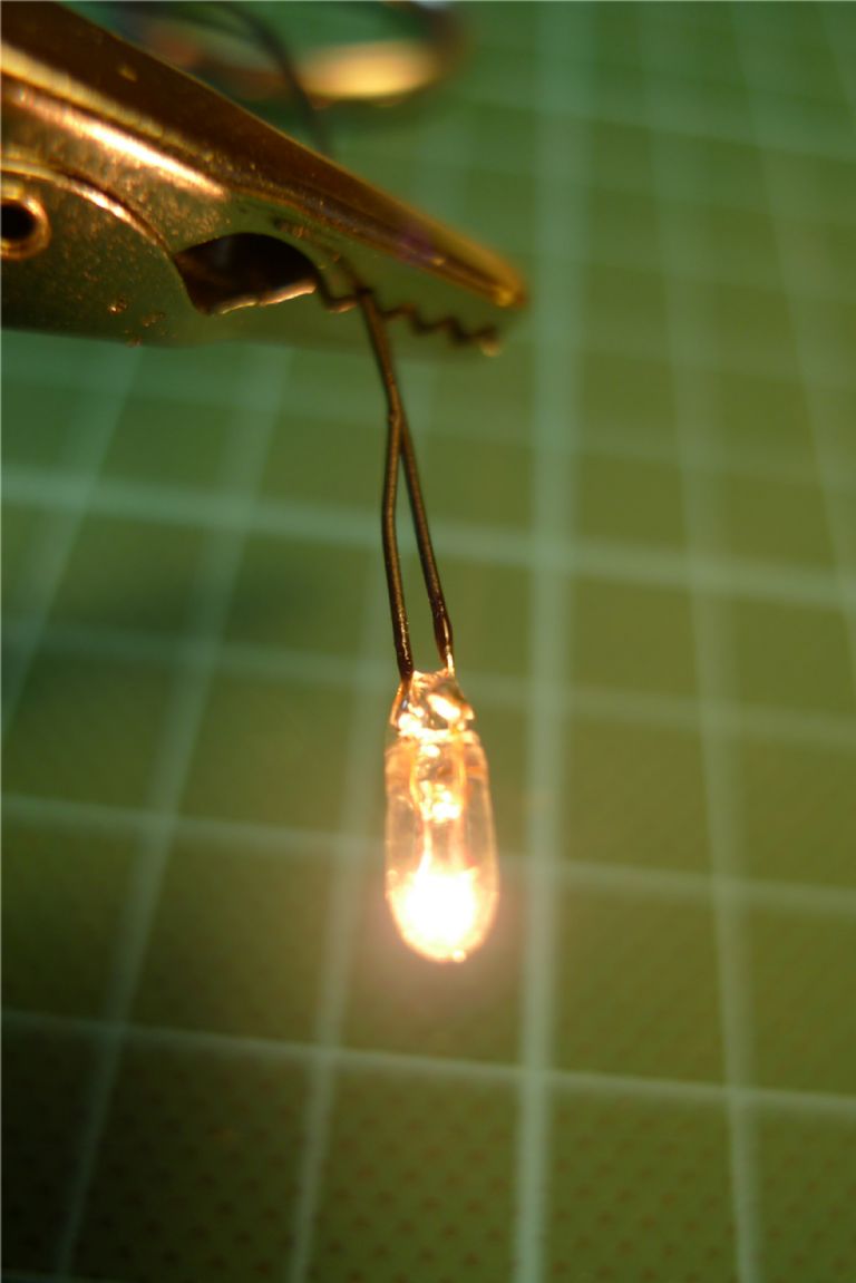
… quickly checked that the grain-of-wheat lamp was working as it should …
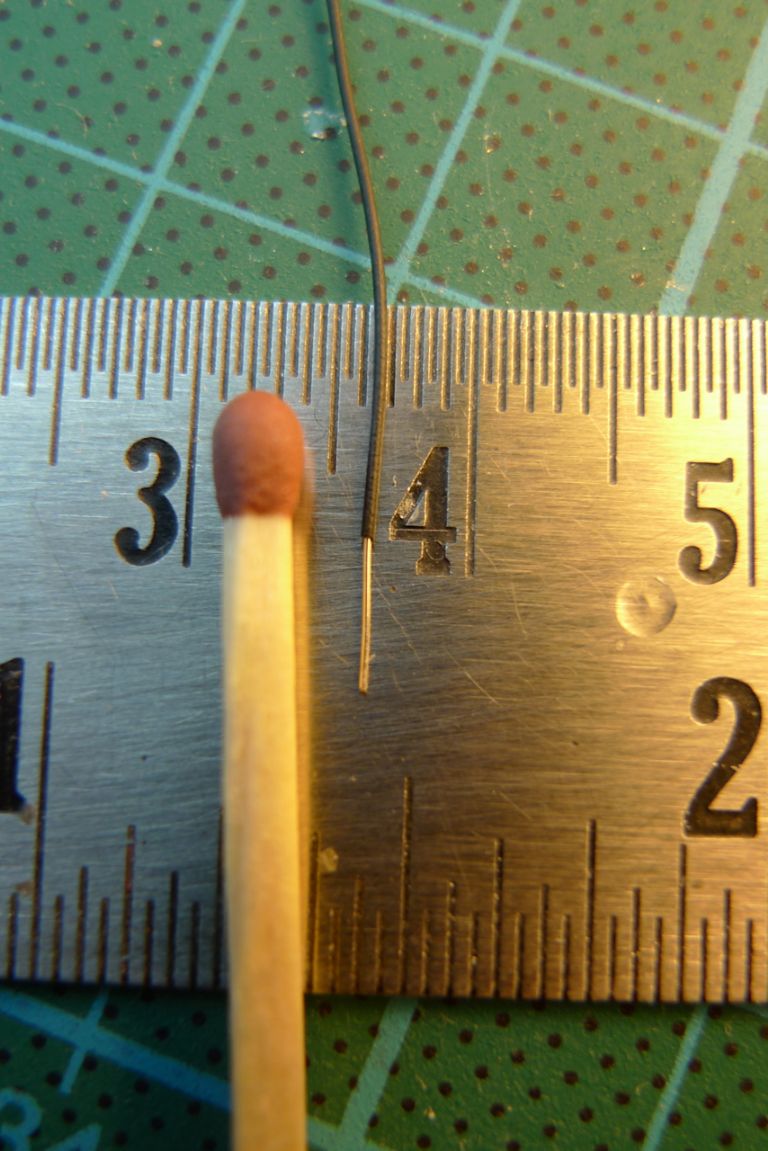
… and then proceeded to change the wiring to the thinnest, isolated cable I was able to find – the 0.55 mm wire sold by The Component Shop.
After carefully peeling away the old insulation to lay bare the bulb connectors, the original wires were desoldered and the new, much thinner one soldered in place instead. The connectors were then isolated again with a couple of generous dollops of thick CA glue.
I also needed to sort out how to get these cables down below deck in a both discreet and splash tight way. I first drilled two holes through the deck under where the mast sourround would sit …
… then drilled the mast surround base and inserted and glued two short pieces of 1 mm brass tube, through which the 0.55 mm wire will pass, albeit only just.
The mast foot was then permanently bolted in place, and the paintwork touched up (hence the masking tape to guard against an involuntary mis-sweep with the paintbrush). The two tubes can hardly be seen, and although not secure against water under any form of pressure, with the wire passed through they should be completely splash and wash proof (and if water pressure is ever applied at this point it will be because the ship has sunk, in which case it won't really matter whether or not there is any additional water ingress here
 )
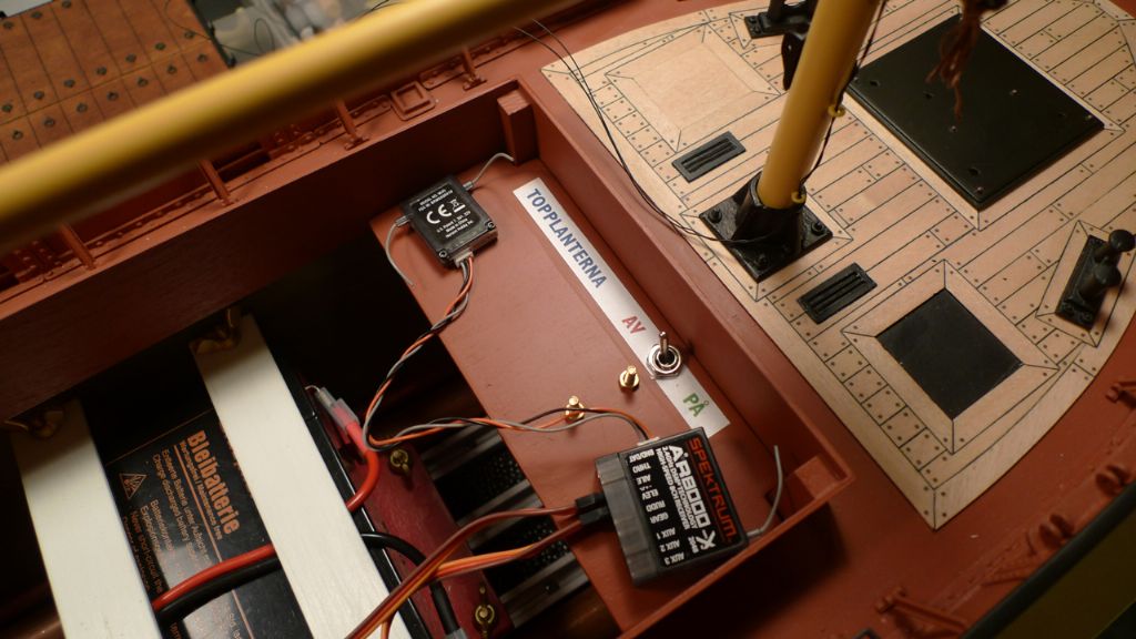
)I also made up a simple plywood tray to sit under the cargo hatch, just aft of the forrard coaming, to carry the r/x on the upper side …
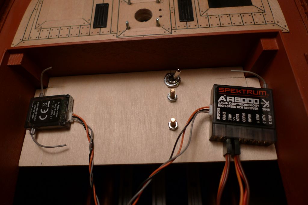
… and a 2×1.5V battery pack on the underside, to feed the top light. Once the mast is put in place for good, and the top light wires have been passed through their pipes to below deck, they will be soldered to the as yet free end of the mini-Deans connector seen sticking up here.
With a bit of paint and a label ("topplanterna" = top light, and "av" and "på" I think you can guess the meaning of) added, the tray was ready to go in. It is just a light push fit, but sits very stable and as it won't really be subjected to any forces, I won't bother securing it any further than that.
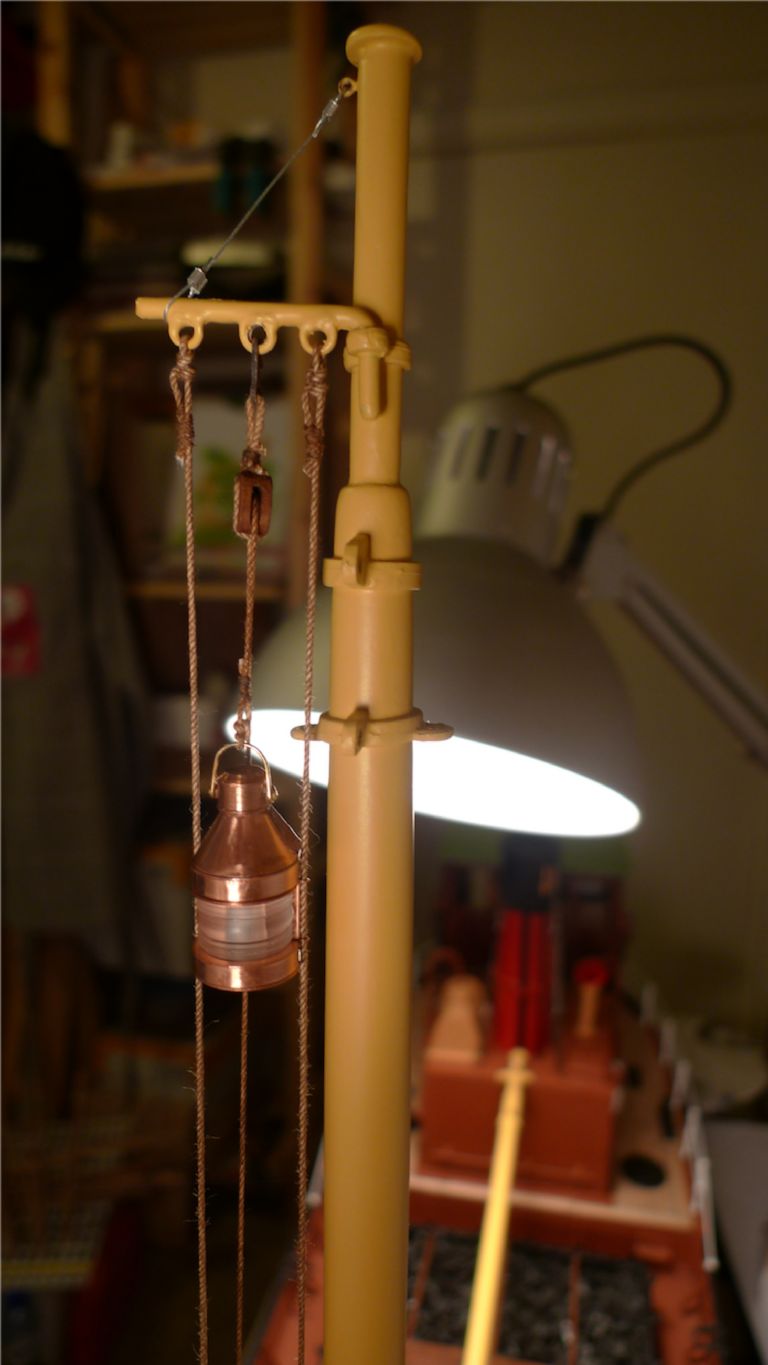
I finished this chppater of the build by test-flying the top light from its outrigger. The ropes and pulley used for this here are only temporary, though, and will be replaced at a later stage of the build.
To be continued …
/Mattias
Edited By Banjoman on 06/12/2014 22:55:48
8 December 2014 at 08:40 #54177Banjoman
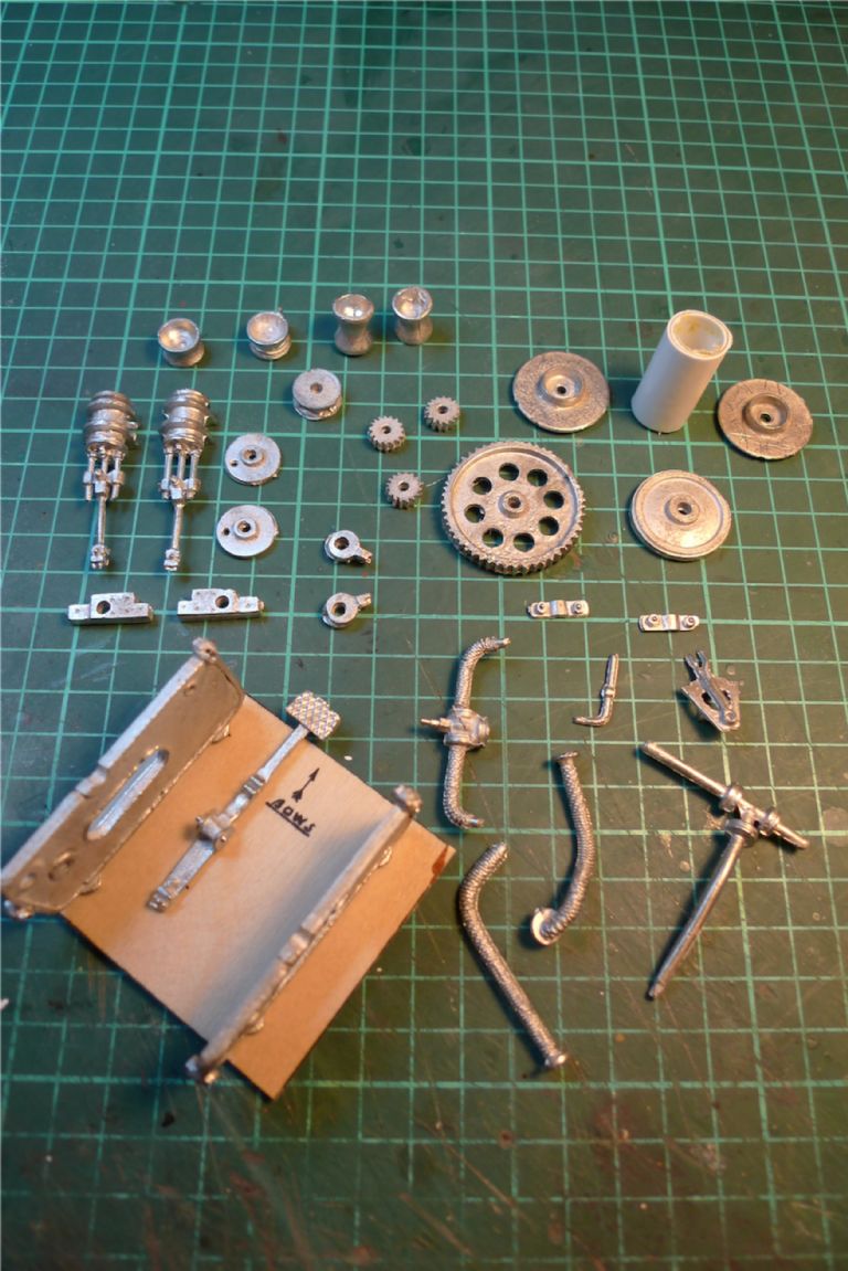
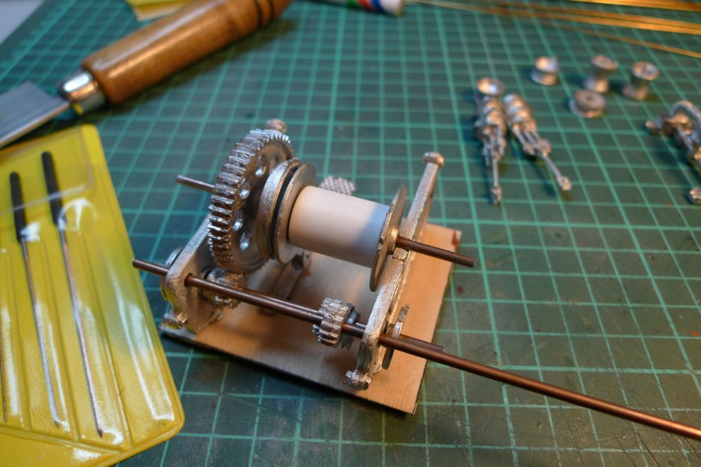
Participant@banjomanIt is a phrase so frequently used that I think it may have become a bit of a cliché, when the winch on this type of of model is described as "a model in its own right"; nevertheless, as is so often the case with clichés, I'd say that the phrase pretty well sums it up! With 31 separate castings plus various bits of rod for axles, plastic tube for the main drum etc. it is all in all a pretty little challenge of its own.
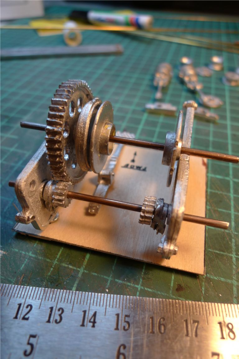
I decided to use the supplied piece of plywood base, with printed marks for where the side pieces and brake pedal arm should go, as an assembly jig only, and set out trying to understand how everything ought to go together. The instructions furnished consisted of an exploded diagram, no more no less, and some photos of the finished thing.
However, a build thread for the Highlander kit over on the Modelboat Mayhem site included a series of very detailed stage by stage photos of the assembly, and wwas of great use to help me figure what should go where and how.
Having thus done a bit of homework, I got down to cleaning up castings and dryfitting various parts.
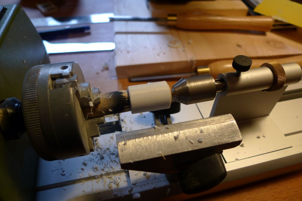
At first I also had some difficulties cutting off squarely an appropriate length of the plastic tube furnished to make up the winch drum; no matter whether cutting with a scalpel or a razor saw, the cut always ended always up a tad too oblique to do, and I began to fear that the material would run out before I got it cut properly. I then hit on the idea, however, to push fit in onto a short piece of scrap dowel, and to mount it in the micro lathe where getting perfectly square cuts became a doddle …
… so, after checking that the cut-off length was just so …
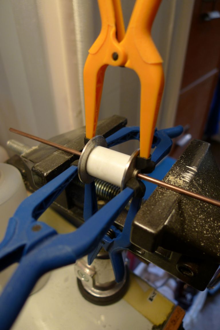
… the drum assembly could be glued together with epoxy (the only glue I found that would really grip on the plastic involved).
To be continued …
/Mattias
-
AuthorPosts
- Please log in to reply to this topic. Registering is free and easy using the links on the menu at the top of this page.
Code of conduct | Forum Help/FAQs
Latest Replies
Home › Forums › Building Kits › Topics
-
- Topic
- Voices
- Posts
- Last Post
-
-
Todays Boating
1
2
…
200
201
Started by:
 ashley needham
in: All things floating
- 83
- 5,003
-
8 minutes ago
 ashley needham
-
The new journey begins
1
2
3
Started by:
 mick east
in: Build Blogs
- 9
- 52
-
1 day, 9 hours ago
 mick east
-
New Website Forum – Discussion Topic
1
2
…
7
8
Started by:
 Colin Bishop
in: News and Feedback
- 20
- 183
-
1 day, 16 hours ago
 Colin Bishop
-
Tin Plate Clyde Puffer
1
2
…
7
8
Started by:
Len Morris 2 in: Scratch build
- 12
- 177
-
1 day, 17 hours ago
 Richard Simpson
-
Puffer advice
Started by:
 Alasdair Allan
in: All things floating
- 4
- 20
-
1 day, 18 hours ago
Len Morris 2
-
Kempton steam open days incl boats
Started by:
 ashley needham
in: All things floating
- 2
- 7
-
2 days, 4 hours ago
 ashley needham
-
Purchasing Kits.
Started by:
Michael Cole 8 in: Building Kits
- 6
- 15
-
3 days, 2 hours ago
 ashley needham
-
Kempton Park Steam Engines
Started by:
 Colin Bishop
in: Shows and Events
- 1
- 1
-
3 days, 12 hours ago
 Colin Bishop
-
another Clyde Puffer
1
2
Started by:
mmcp42 in: Scratch build
- 7
- 45
-
3 days, 14 hours ago
mmcp42
-
Wanderer III
Started by:
grich101 in: Scratch build
- 4
- 5
-
6 days ago
 Ray Wood 3
-
Two more of my old models gone
Started by:
Bob Wilson in: Static modelling
- 1
- 1
-
6 days, 11 hours ago
Bob Wilson
-
Two more of my old models gone
Started by:
Bob Wilson in: Static modelling
- 1
- 1
-
6 days, 11 hours ago
Bob Wilson
-
May 2024 issue not in the archive?
Started by:
mmcp42 in: News and Feedback
- 2
- 5
-
1 week, 2 days ago
mmcp42
-
My Clyde Puffer
1
2
…
9
10
Started by:
James Hill 5 in: Scratch build
- 17
- 241
-
1 week, 4 days ago
Len Morris 2
-
Wild Duck meets Eventide
1
2
Started by:
Tim Rowe in: Scratch build
- 5
- 30
-
1 week, 4 days ago
 Tim Rowe 1
-
Ben Ain
1
2
3
4
Started by:
 Richard Simpson
in: Steam powered models
- 8
- 99
-
1 week, 4 days ago
 Richard Simpson
-
getting the boat to pond
Started by:
 Alasdair Allan
in: All things floating
- 3
- 8
-
2 weeks, 1 day ago
 ashley needham
-
MFA Motors ceasing business
Started by:
 Colin Bishop
in: All things floating
- 3
- 3
-
2 weeks, 5 days ago
 ashley needham
-
HMS Glory
Started by:
 Colin Miller
in: Build Blogs
- 4
- 18
-
2 weeks, 6 days ago
 Colin Miller
-
ss Miltiades 1901
Started by:
 Colin Bishop
in: Scratch build
- 2
- 3
-
3 weeks ago
 Colin Bishop
-
Amati j class yacht kit
Started by:
 ashley needham
in: Buy/Sell or Trade
- 4
- 6
-
3 weeks, 1 day ago
 ashley needham
-
North West Model Shipwrights Society
Started by:
Bob Wilson in: Club News
- 6
- 17
-
3 weeks, 3 days ago
Bob Wilson
-
ballasting a paddle steamer
Started by:
 Alasdair Allan
in: All things floating
- 5
- 17
-
4 weeks ago
 Colin Bishop
-
Aerokits pt boat bulkhead plans wanted
Started by:
Roo Hawkins 1 in: All things floating
- 1
- 1
-
4 weeks, 1 day ago
Roo Hawkins 1
-
building a display case
Started by:
 Alasdair Allan
in: All things floating
- 5
- 17
-
1 month ago
 Colin Bishop
-
Todays Boating
1
2
…
200
201
-


