The world's leading magazine for all model boating interests
Eilean Mor
Eilean Mor
Home › Forums › Building Kits › Eilean Mor
- This topic is empty.
-
AuthorPosts
-
11 November 2014 at 12:39 #53551
Banjoman
Participant@banjomanAs this stage of the build began involving waiting for paint to dry (as always one of the most exciting shows on Earth …
 ) I used the "don't touch" periods to begin the assembly of an additional kit that I'd recently bought, namely copper etch navigation lights from Marten, Howes & Baylis (**LINK**).
The navigation lights included in the kit were, as most of the other fittings, of white metal and fine as such; however, they don't hold a candle (!) on the MH&B ones, which are by far the nicest, most realistic-looking, working period ship's lights that I have been able to dig up. They do not come cheap, I fear (arms and legs do almost enter into the equation) but they really do look the part, and are indeed 1:24 scale, so I found myself unable to resist them …
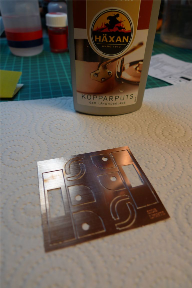
Anyway, construction began by giving the copper parts a thorough polish with Häxan ["The Witch"] kopparputs, i.e. the Swedish equivalent of Brasso.
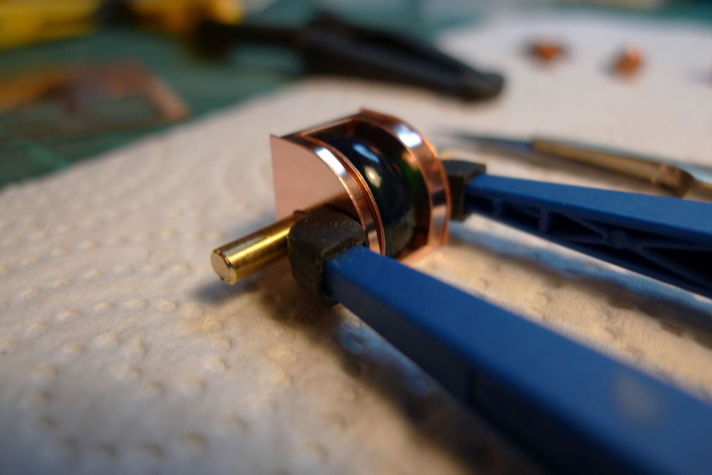
Once the copper shone as it ought to, latex gloves were donned to avoid pesky fingerprints, and the lights assembled. It was rather fiddly, not least because of said latex gloves, although the brass mandrel that came with the kit was a good help to keep everything nicely aligned …
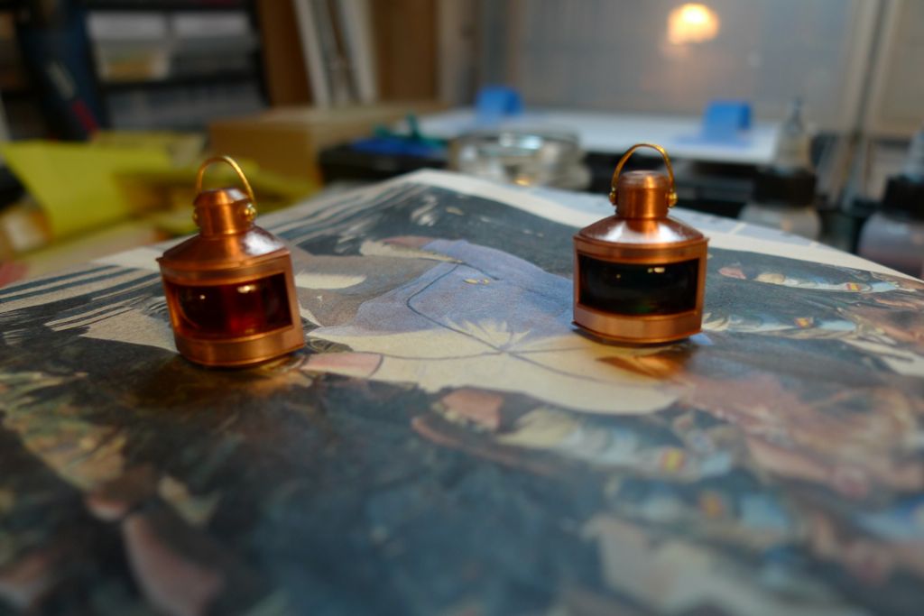
… and eventually I had as nice a pair of navigation lights ready as I could wish for! They were then given a coat of clear varnish so that they can be handled with bare hands without too much fear of tarnishing the copper with fingerprints.
To be continued …
/Mattias
Edited By Banjoman on 11/11/2014 12:40:32
Edited By Banjoman on 11/11/2014 12:41:48
Edited By Banjoman on 11/11/2014 12:44:24
12 November 2014 at 09:18 #53577Banjoman
Participant@banjomanTime to start painting in earnest! But what paints to use?
I had as already mentioned decided to use an airbrush, but for the main hull surfaces I still hesitated between airbrush and spray can. The Halford's paints that one so often sees references to in UK build descriptions are not available this side of the Channel (or at least I haven't found them anywhere) but of course car paints are as ubiquitous here as anywhere else, so I went out and bought a can of red car primer in order to be able to better compare and to make a fully informed choice.
I was doubtful about this, though, as I had had some less fortuitous experiences of spray cans in days of yore (overspray, disagreeable odors, on/off spray mode only, paint runs, etc. etc.) but that was then and now is now, so at least a test would, I felt, be in order.
That test, however, quite confirmed my long held view that spray paints and I do not work well together, and not least the fumes and the overspray involved very quickly put me off the idea. Because I wanted to be able to paint indoors, and because I have no fume extraction system, it should preferably be a non-solvent based paint, i.e. an acrylic of some sort. However, as it is supposed to be a working model, the paint, at least for the hull, should ideally be a bit stronger and cover better than those used by plastic modellers for static builds.
In the end I decided to try a polyurethane based acrylic paint, Vallejo Premium RC-Color, developed by Vallejo primarily for r/c car bodies but often also used for painting e.g. motorcycle helmets (**LINK**), and thus supposed to be able to take at least a bit of a beating.
Although the number of solid colours available ready mixed is limited to 20, the paint is airbrush ready out of the bottle with a slightly larger needle (I mainly use a 0.6 one) in the airbrush, and the various colours can of course be mixed to one's heart's content.
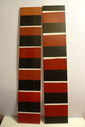
Given the limited number of colours available, there was nothing in the range close to a typical red primer/anti-fouling paint, so I set out to test various mixes, with this result:
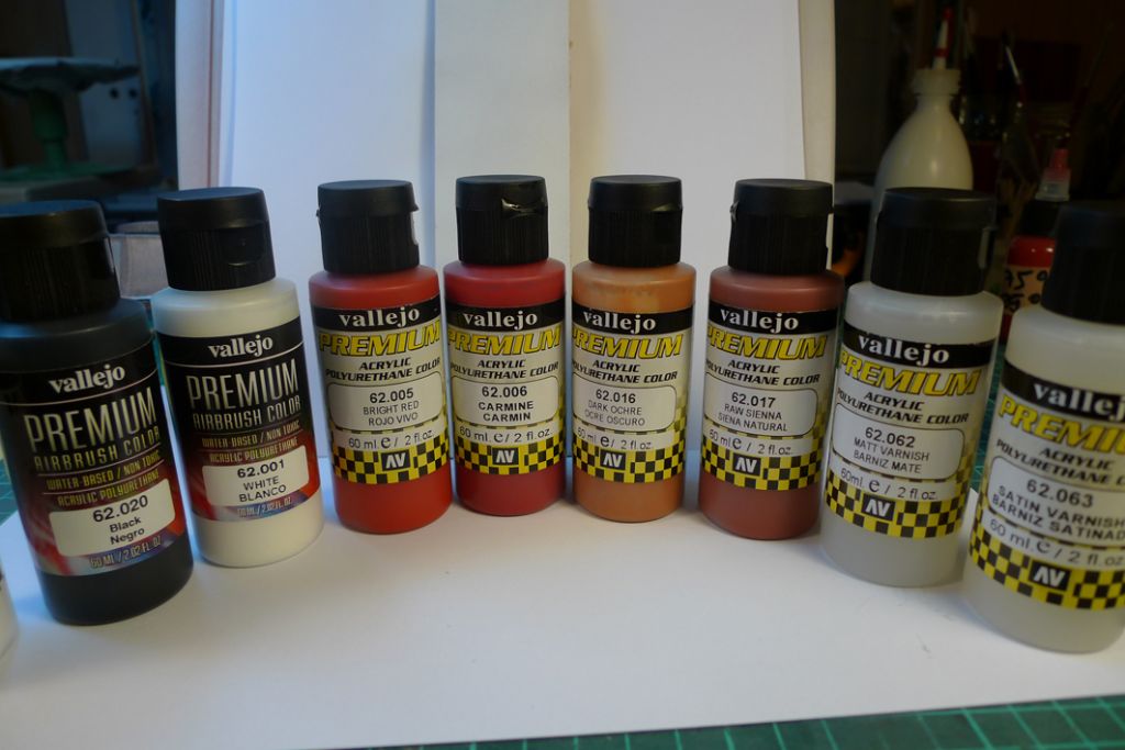
In the end I decided to use the middle sample from the right hand test piece, a 50/50 mix of 62.005 (Bright Red) and 62.017 (Raw Sienna). In comparison, the third colour up on the left hand side is the red car primer from that spray can I'd bought … My mix is a tad redder, but then again I quite like that …

Anyway, before any paint were applied at all, I first cleaned and degreased the hull thoroughly with mildly soapy water and then again with methylated spirits …
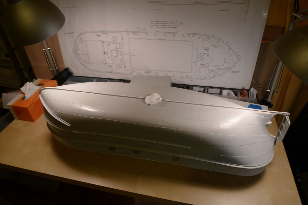
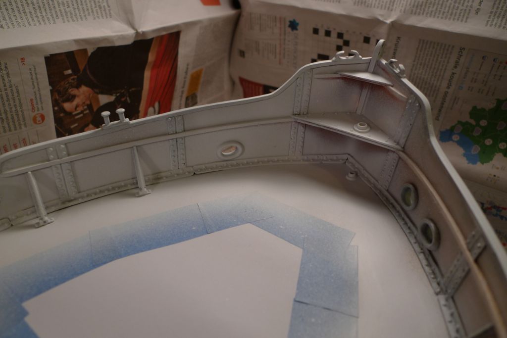
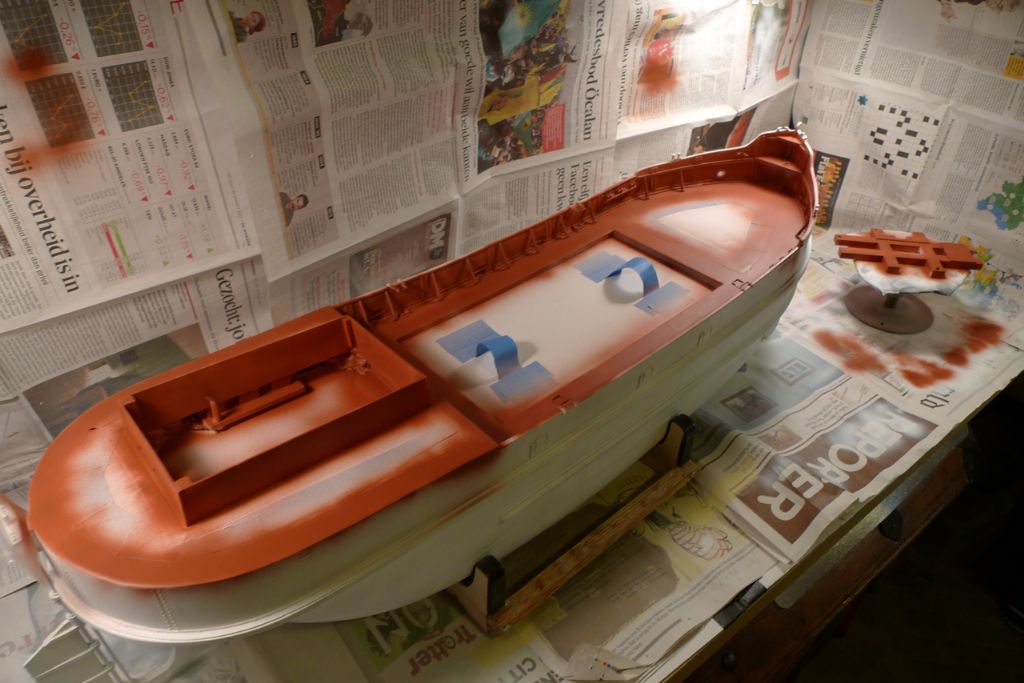
… after which it was time to start putting on the first thin layers of white primer!
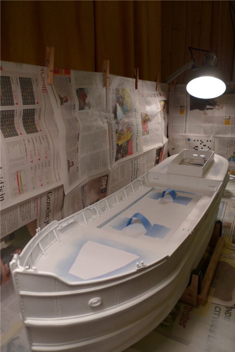
A couple of days and several coats of white primer later, there she were: Moby Dick, the White Puffer!

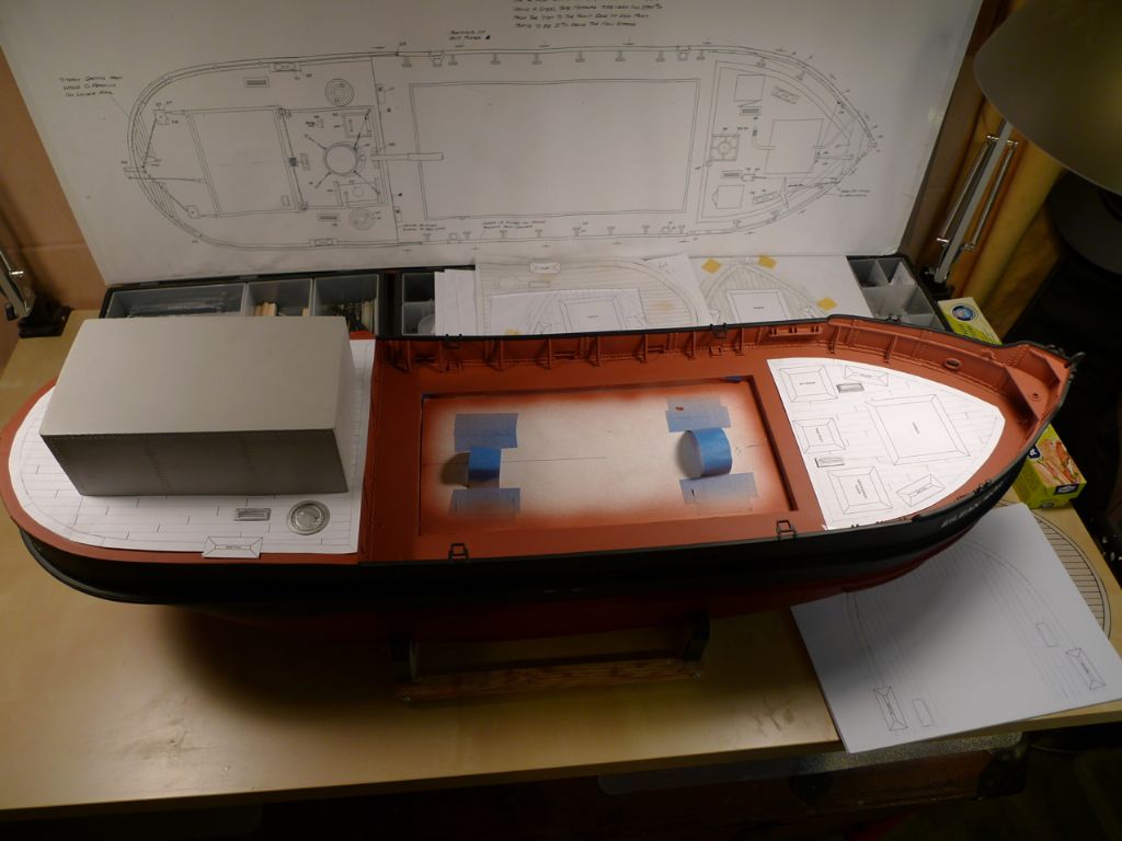
As the photo shows, I had also masked off parts of the fore- and quarterdecks, in order to be able to glue at least most of the planking that were to come directly on to the plywood rather than on to paint.
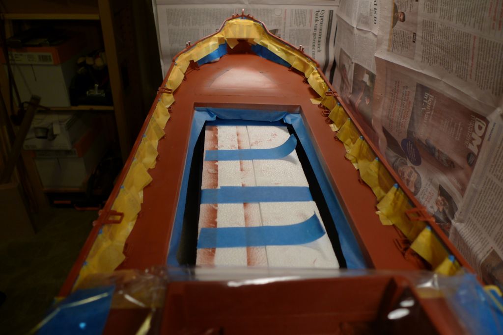
Next up was a medium brown colour for the deck and the inside of the bulwarks, this time a 50/50 mix of 62.016 (Dark Ochre) and 62.017 (Raw Sienna).
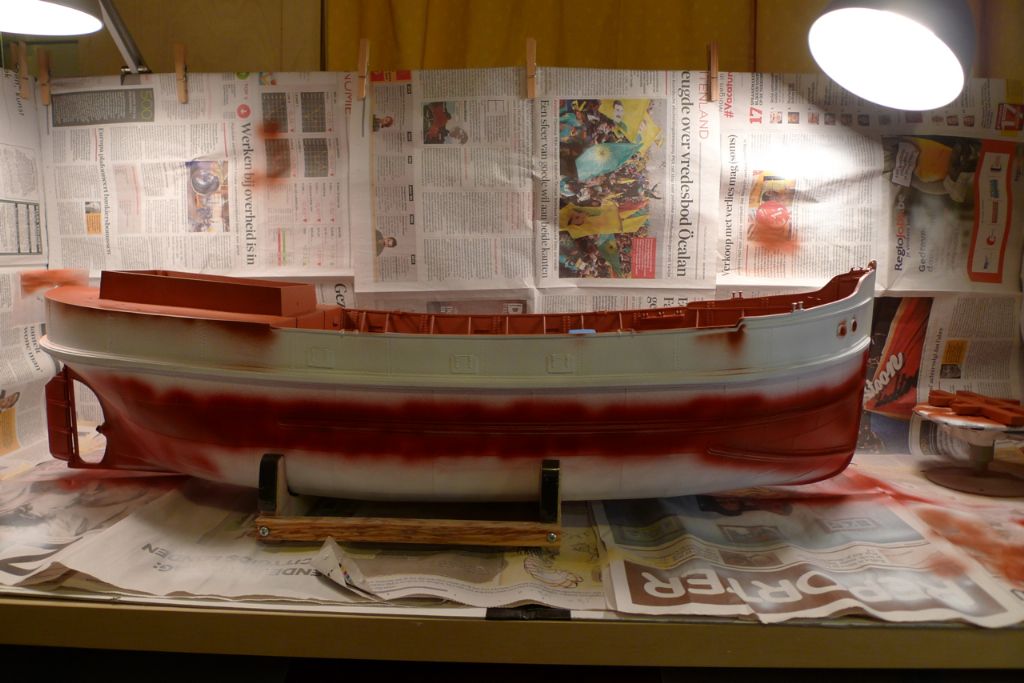
Whence I went on to the bottom paint …
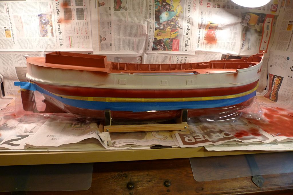
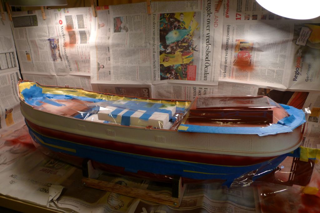
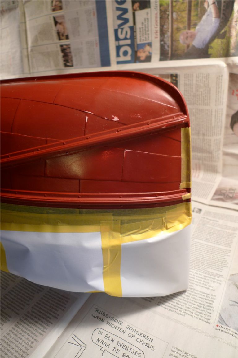
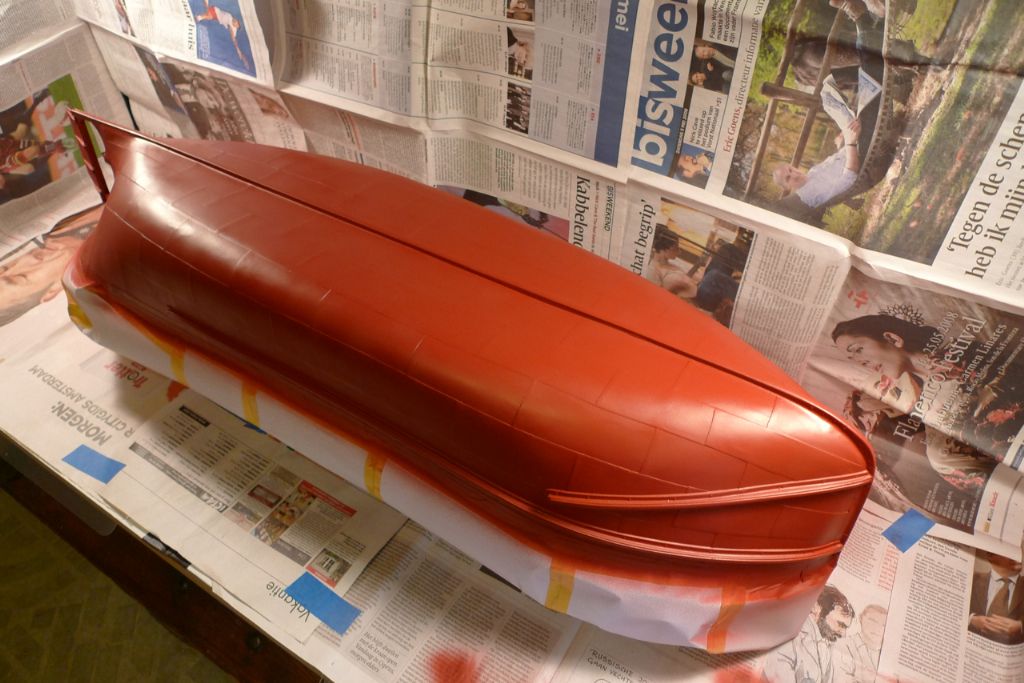
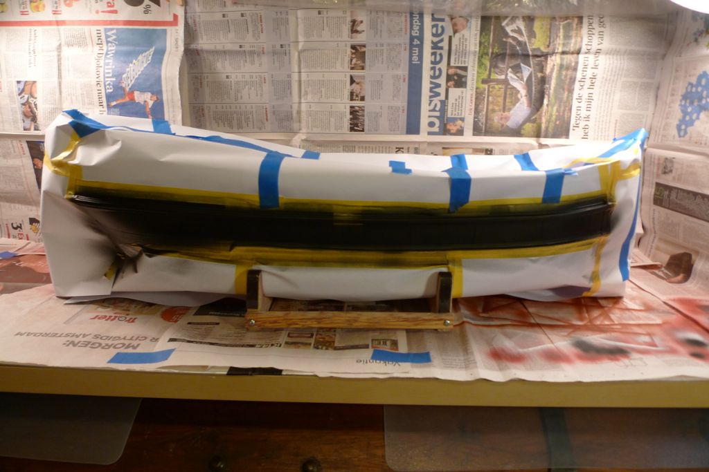
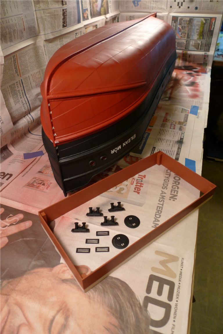
… which, when finished, looked like this, put on go a bit above the waterline, as everything between the waterline and the inside lower edge of the bulwark cappings will be black (i.e. a fairly simple masking job, and also black is handy paint to put on last as it tends to cover very well).
The spray box by the way is a fairly simple job, made up from 3 mm thick cardboard sheets, taped together with strong clothbacked tape in such a way that they can be folded back on each other like a Monopoly board, and thereby more easilly stored. I then just fasten newspaper with clothespins and masking tape, to avoid a build-up of paint on the cardboard. It works well as a general backing to catch overspray and after painting can easilly be covered over by a bit of plastic to keep off the worst of any dust floating around in spite of my pre-painting workshop cleaning session
Edited By
13 November 2014 at 08:45 #53603Banjoman
Participant@banjomanNext up, it was time to decide on and mask the waterline.
Having studied a number of period photos of Clyde Puffers, I would say that many if not most of these ships were not painted to have a classic or conventional (if I may call it that) flotation level waterline, i.e. the sort of waterline that one would mark out on a model by putting it on a table and going round the hull with a fixed height pen.
Instead, many Puffers were given what I would call a mechanical waterline, i.e. one that largely followed a line in the hull construction, usually a rubbing strake. Strictu sensu this is not even really a waterline at all, but just a two colour paint scheme. But then again, it is also evident enough from old photos that these ships would lie differently in the water depending on what cargo they were carrying and how this had been loaded, often being down considerably by the stern and sometimes by the bows. Seemingly, it was not uncommon practice if the weather looked like keeping fine and the cargo was not too large to load more towards one end of the hold, as this facilitated unloading by hand and bucket under the more primitive circumstances Puffers often met in their more remote destinations.
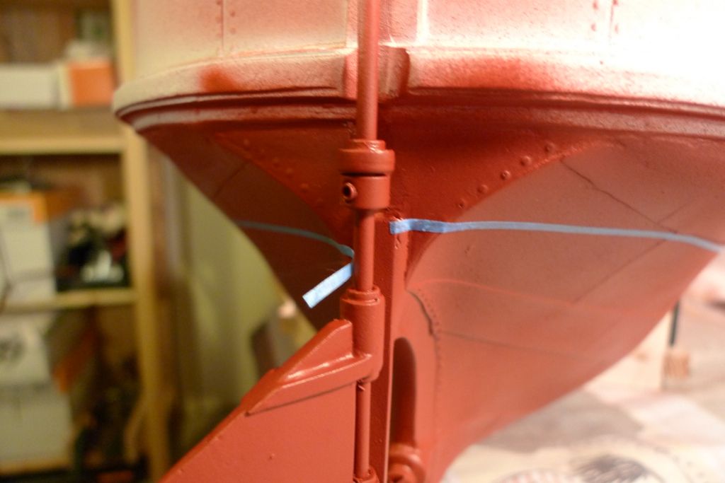
Also, many Puffers even seem to have been painted in their bottom colour all the way up to the upper rubbing strake, with only the gunwhales painted black. This, however, I find a less pleasing look, giving a sort of impression as if the ship had pulled her skirt up to cross a stream or summat … Although common enough, this does not seem to have been ubiquitous, and I therefore felt vindicated in instead painting her black all the way down to just 2 mm above the lower rubbing strake. I marked this out on the hull using a single long strip of 2 mm washi masking tape. This tape is flexible enough to follow the curves perfectly, and by letting it lie just above the top of the rubbing strake for as long as there was one, I automatically got the paint line at the right level for the forward two thirds of the hull. It was then a fairly easy task to adjust the tape under the stern until I was satisfied with the curves, and to let the tape ends finally meet behind the rudder post.
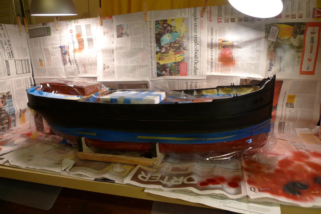
On top of this first strip of masking tape, the rest of the lower hull masking was built up in stages with, in order, Tamiya masking tape, standard painter's masking tape and finally a sheet of book cover plastic.
A similar masking process was followed along the inside of the bulwarks: first 2 or 3 mm washi tape around the tops of the struts and along the under edge of the bulwark cappings, then Tamiya tape and painter's tape …
… and finally another piece of book cover plastic.
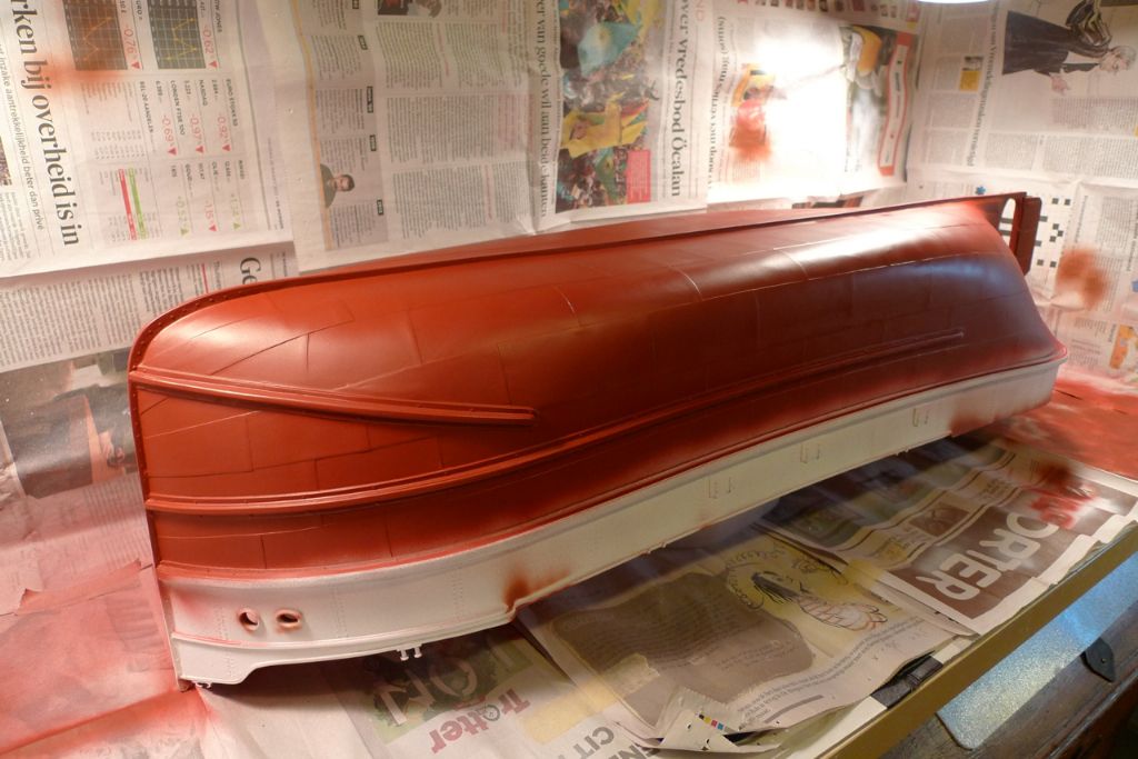
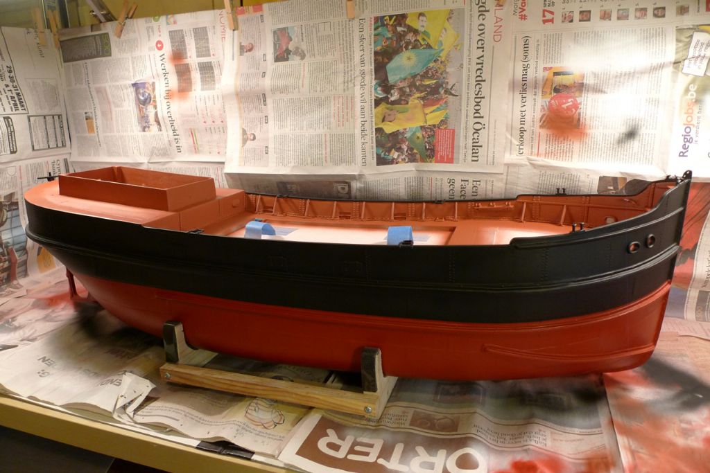
Then it was but to blast away with the black paint …
… whiich, after being left to dry for a couple of days, looked like this when the masking came off. Some minor touch-ups and fixes were still needed, mainly along the inner bulwarks where the difficult masking around the struts had sometimes let a few droplets of black paint through, but on the whole it all worked out allright.
To be continued …
/Mattias
Edited By Banjoman on 13/11/2014 08:48:12
Edited By Banjoman on 13/11/2014 09:09:51
14 November 2014 at 09:34 #53626Banjoman
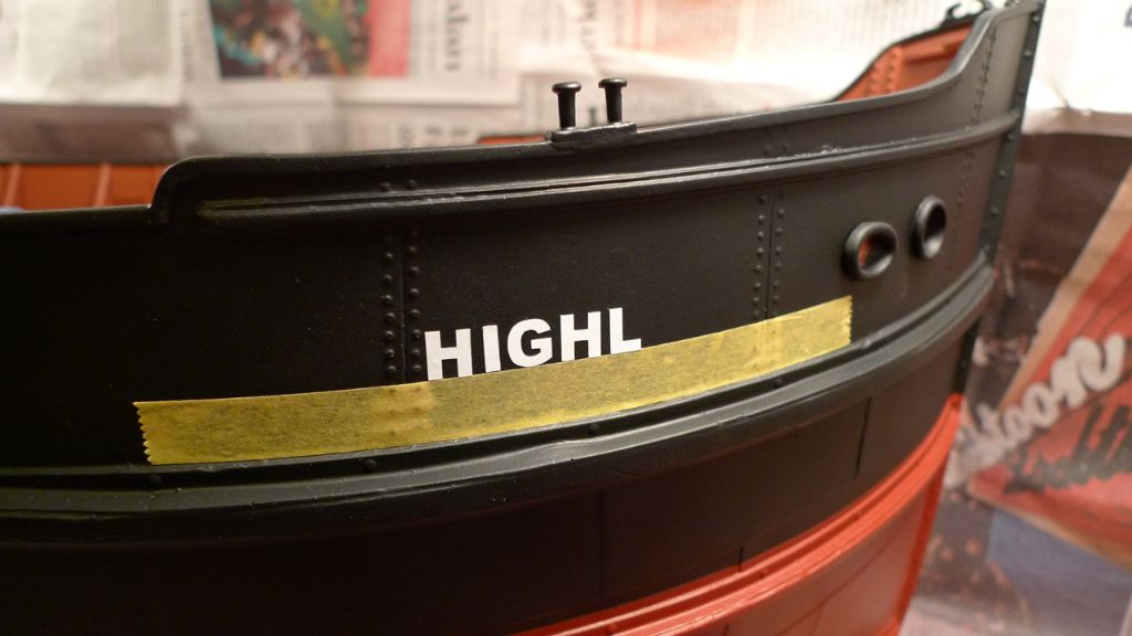
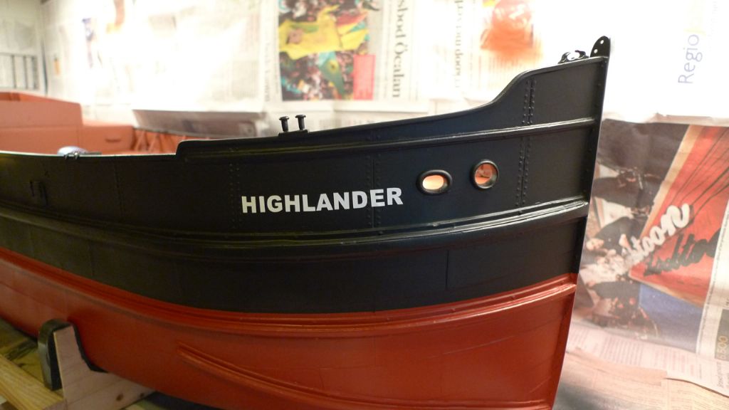
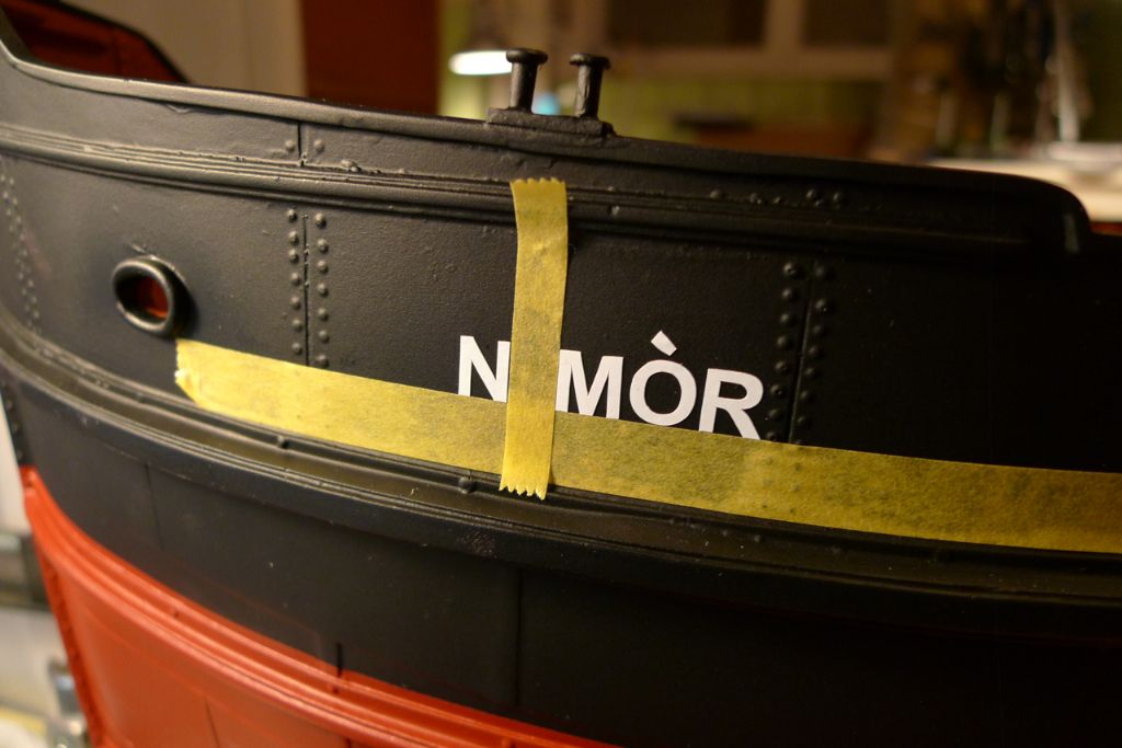
Participant@banjomanWith the hull painted, I got out the lettering that had come with the kit, and which contained the letters needed to make up the kit name (Highlander) on both sides of the bows, and the suggested port of registry (Glasgow) on the stern quarters.
Although I had already been toying with the idea of giving the ship another name (given that there is no specific prototype, this would of course not be problematic in any way), I nevertheless decided to give her a go as "Highlander", and thus began applying the lettering.
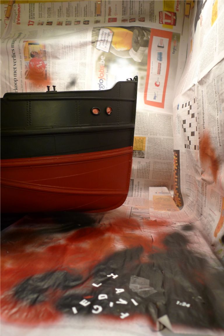
I was not best pleased, though, with the result: in particular the second "H" and the "R" came out a tad too wonky for my taste, and the supplied lettering was not very pleasant to work with either. The adhesive grabbed too much too soon, making repositioning almost impossible, while the letters were quite susceptible to tearing or deformation if not handled very carefully. For example the original "I" was ruined when I first tried to adjust it, and so I had to cut a new one out from the edges of the vinyl sheet. This was doable for the letter "I", which in this font is just a rectangle anyway, but I did not fancy the prospect of trying to make up a new "G" or something of that curved ilk, should I misapply one at some point.
I therefore decided to discard the provided lettering, and sent off for some BECC letter sheets instead.
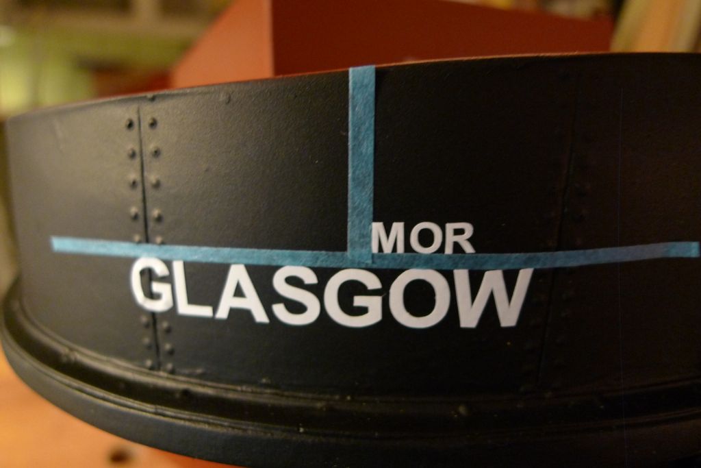
The BECC letters I found to be far superioir in quality! They have a good grab, but can nevertheless be slid that quarter or even tenth of a millimeter which will often make all the difference between OK and awry. With a bit of care they can also be removed and reapplied, and they retain their shape very very well indeed even when handled extensively.
Given that I now had access to the full alphabet, the option of a new name became that much more tempting. Being pretty much a confirmed Islay man when it comes to whiskies, I first considered a couple of my favuorite tipples, namely the Uigedail and Corryvreckan from Ardbeg distilleries. In particular the latter would have looked rather good with the Gaelic spelling of the whirlpool ater which it is named, Coire Bhreacain.
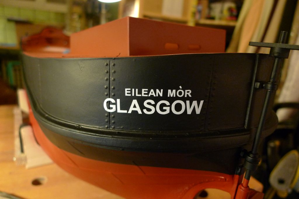
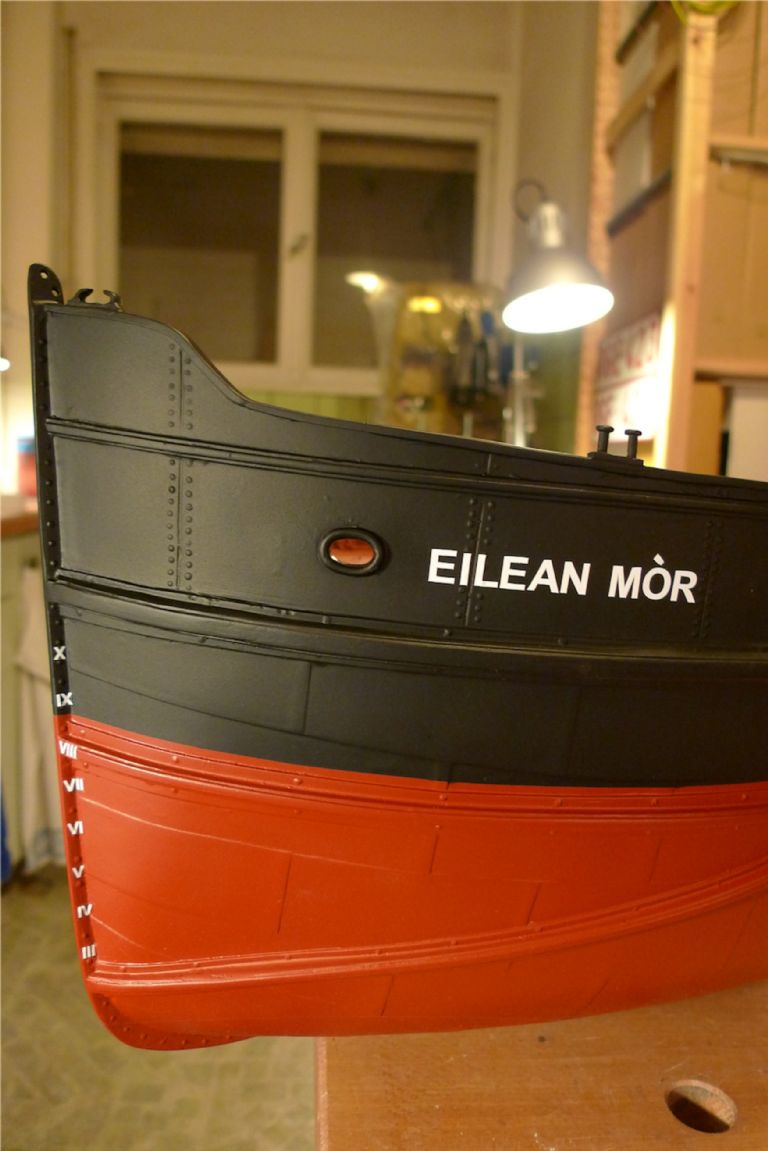
However, some further research threw up the equally Gaelic "Eilean Mòr" which really caught my fancy. It means "large island" or "big isle", and is a common island name (**LINK**) in the West Scotland waters that were home to the Puffer trade. The most famous one is probably the Eilean Mòr in the Flannan Isles, due to the mysterious disappearance from there of three lighthouse keepers in 1900. There has also been at least one real life Puffer with a similar name, the Eilean Eisdail.
I was further attracted to this name by the fact that the idiomatic Swedish translation would be "Storskär" (Big Skerry), which is not only the name of several islands in the Stockholm archipelago, but also the name of a beautiful Stockholm archipelago steam ship (http://sv.wikipedia.org/wiki/S/S_Storsk%C3%A4r), still in regular service after more than a hundred years.
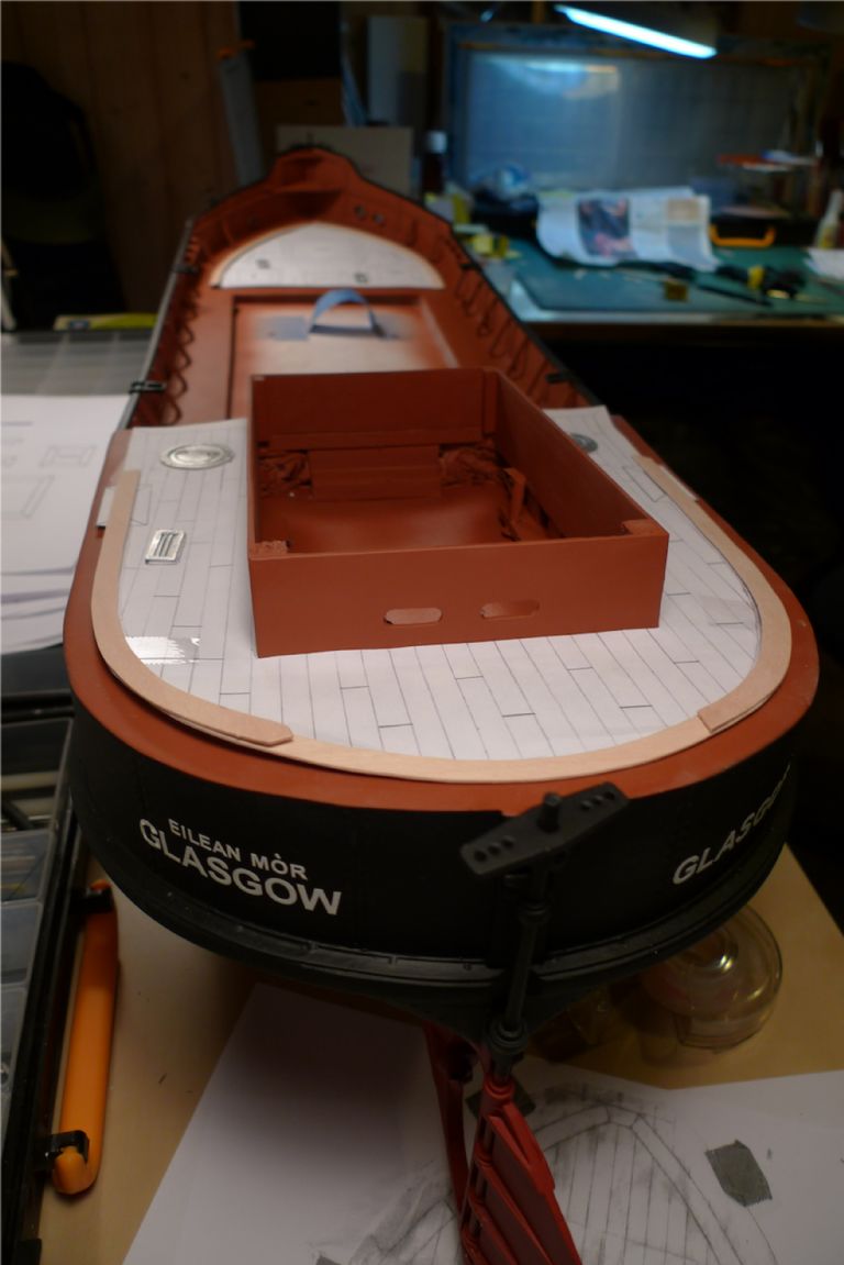
Thus it was decided: Eilean Mòr she would be, and I began lettering anew!
I saw no reason, though, not to stick with Glasgow as a port of registry, so that wasn't changed, altough I of course used BECC lettering here too. Apart from all the other advantages of the BECC letters, they also mould better over e.g. rivet heads than did the kit lettering, something that came in handy several times.
I also added the name of the ship in smaller letters on the port stern quarter, as many Puffer photos show a similar arrangement of some kind to include of the ship's name on the stern.
To be continued …
/Mattias
Edited By Banjoman on 14/11/2014 09:35:38
Edited By Banjoman on 14/11/2014 09:41:39
Edited By Banjoman on 14/11/2014 09:42:47
Edited By Banjoman on 14/11/2014 09:43:51
14 November 2014 at 18:14 #53631IAN_I
Participant@ian_iHi Mattias…
Great work and very detailed build, I hope the Model boat mag takes up your log as an article in the future issues, as not every one looks on line.
Regards,
Ian
16 November 2014 at 10:53 #53654Banjoman
Participant@banjomanThank you very much, Ian, for your comments!
Personally I'm not all that convinced my build is original or special enough, compared with so many others seen here or elsewhere, that it'd merit attention beyond the forum, but it is most kind of you to think and say so!

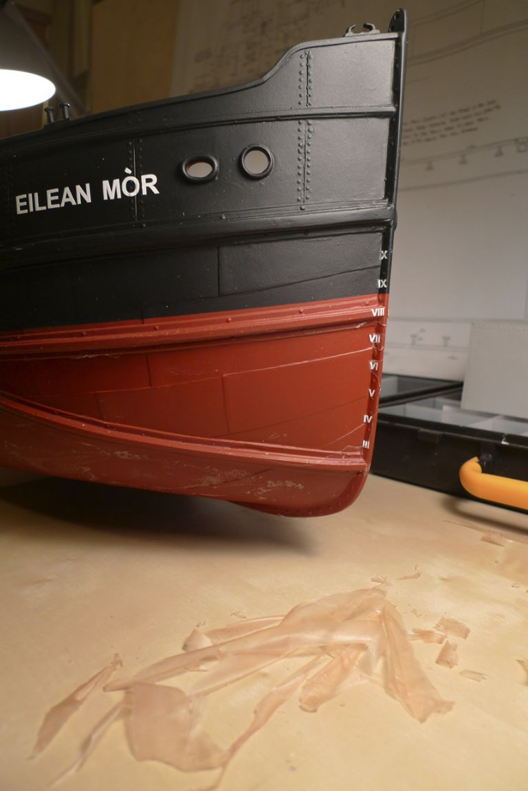
With name and port of registry sorted, I decided to add some depth marking figures on the stem, and also plimsoll and load marks amidships. Although the latter do not always show very clearly or even seem to be there in period photos, most puffers definitely seem to have had depth markings on either the stem or the sternpost, and some photos can be also found of Puffers with load line markings.
I therefore got the 1:24 BECC vinyl sheet of markings, but found that although the distance between markings was to perfect scale (in 1:24 one foot of course becomes half an inch), the numbers themselves looked way too large for such a small ship as a puffer. I think they woud have been spot on on a full size merchant vessel, a tanker or something similar, but on my puiffer they looked disproportionate.
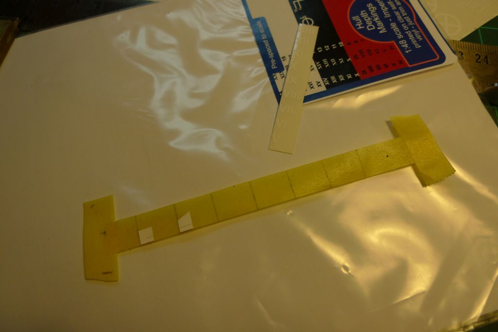
I therefore sent off for the 1:48 sheet as well, where I found the numbers to be just the right size. However, the distance between them would no longer be to scale at 1:24. I would thus not be able to use a continous strip of depth markings, automatically giving the correct spacing, but instead had to space them myself.
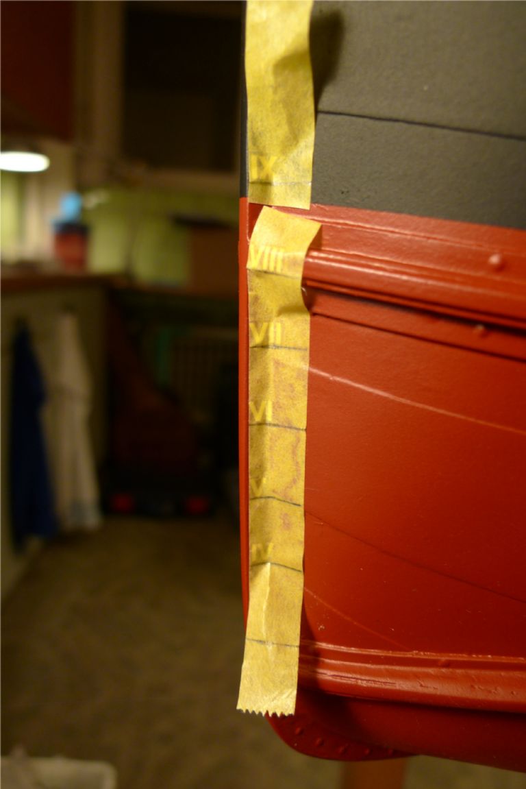
To this end, I rolled out a short length of 18 mm Tamiya masking tape, and marked out in pencil on the non-sticky side the required number of half inch distances. I then turned the tape over, and taped it down, cut out the figures I wanted to use (Roman numerals III through X) and carefully stuck them onto the tape with the vinyl sheet backing still in place.
I then equally carefully removed the backing from the numerals, and offered the whole strip up to the stem. By first pressing down lightly to make the numerals stick to the model, and then very slowly removing the masking tape …
… the depth markings were applied in their correct positions (give or take a few gnats' whiskers; the three foot mark sits more or less an inch and a half, i.e. three feet, above the bottom of the keel but I didn't measure this to the point of exactitude where I could have sworn to the last fractions of an inch) and evenly spaced.
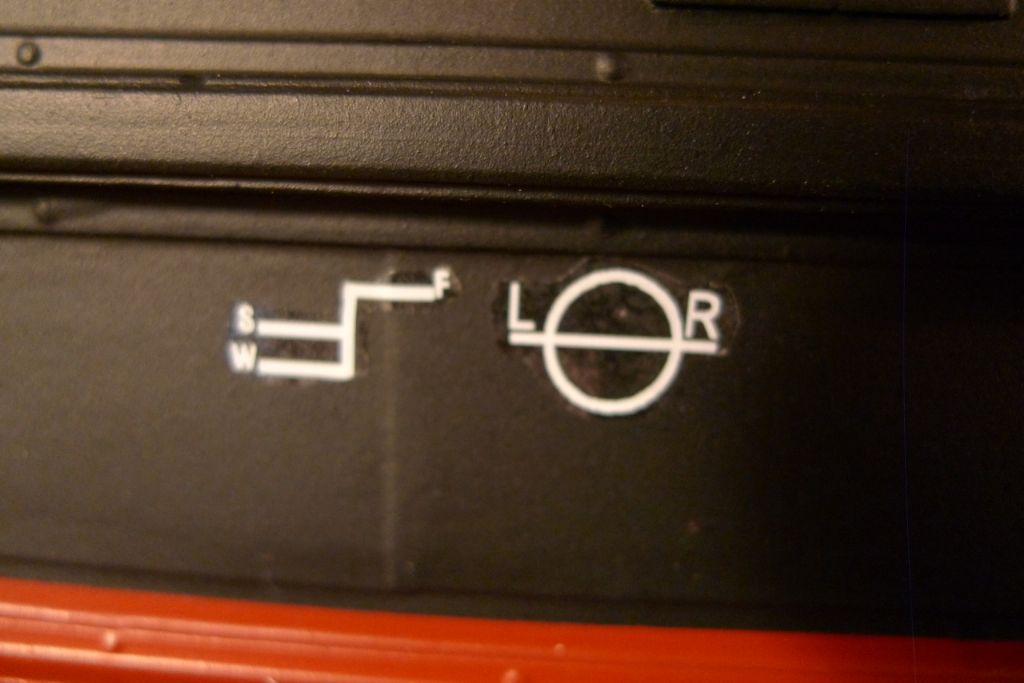
The load marks were of course much easier, and taken from the 1:24 sheet rather than the 1:48 one. The only tricky part of this job was the removal of the unnecessary load lines, as I doubt that even a Puffer that had load marks painted on would have carried those for either the tropics or for the Winter North Atlantic.
I thus decided to keep only the load lines for winter and summer sea water, and for fresh water, and some meticulous trimming of the load line sticker was carried out.
To be continued …
/Mattias
Edited By Banjoman on 16/11/2014 10:53:36
Edited By Banjoman on 16/11/2014 10:53:58
Edited By Banjoman on 16/11/2014 10:55:06
Edited By Banjoman on 16/11/2014 10:58:36
17 November 2014 at 09:38 #53669Banjoman
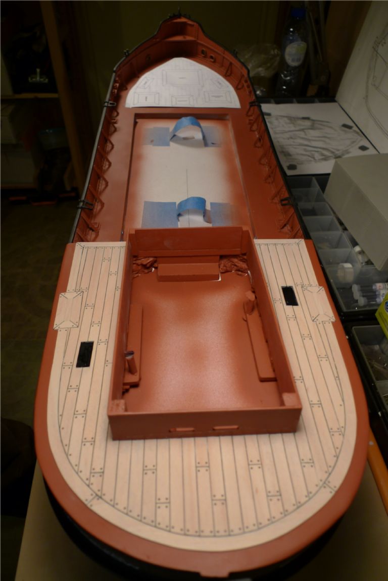
Participant@banjomanAs already mentioned, I decided to replace the printed fore- and quarterdeck overlays with planking. To this end, some forethought and planning was needed.
First up, I needed to ascertain the shape of the foredeck area to be planked. This was not entirely straightforward, as the hull shape was not perfectly symmetrical here.
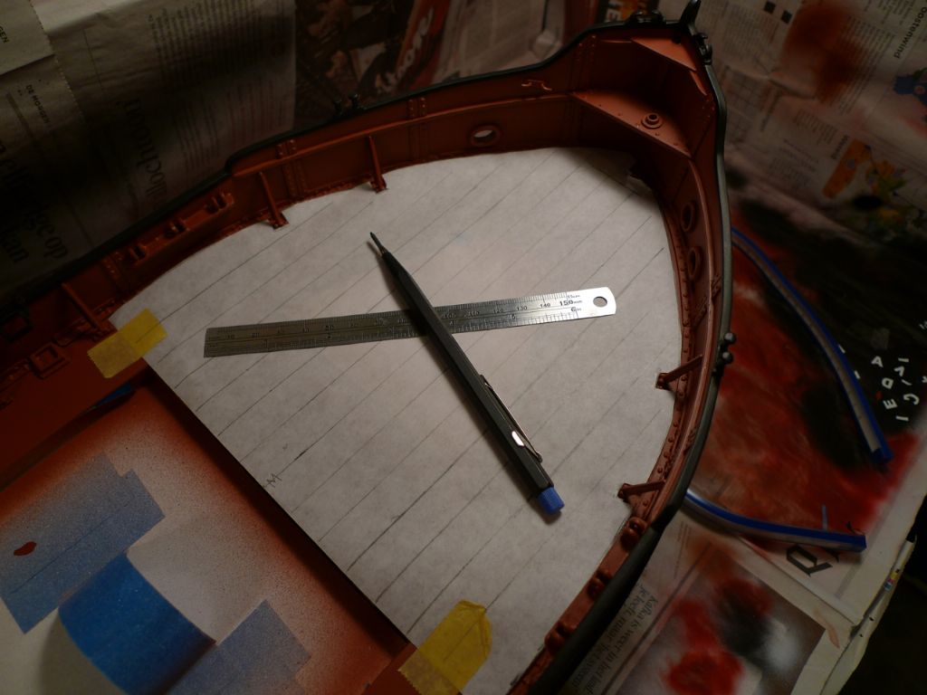
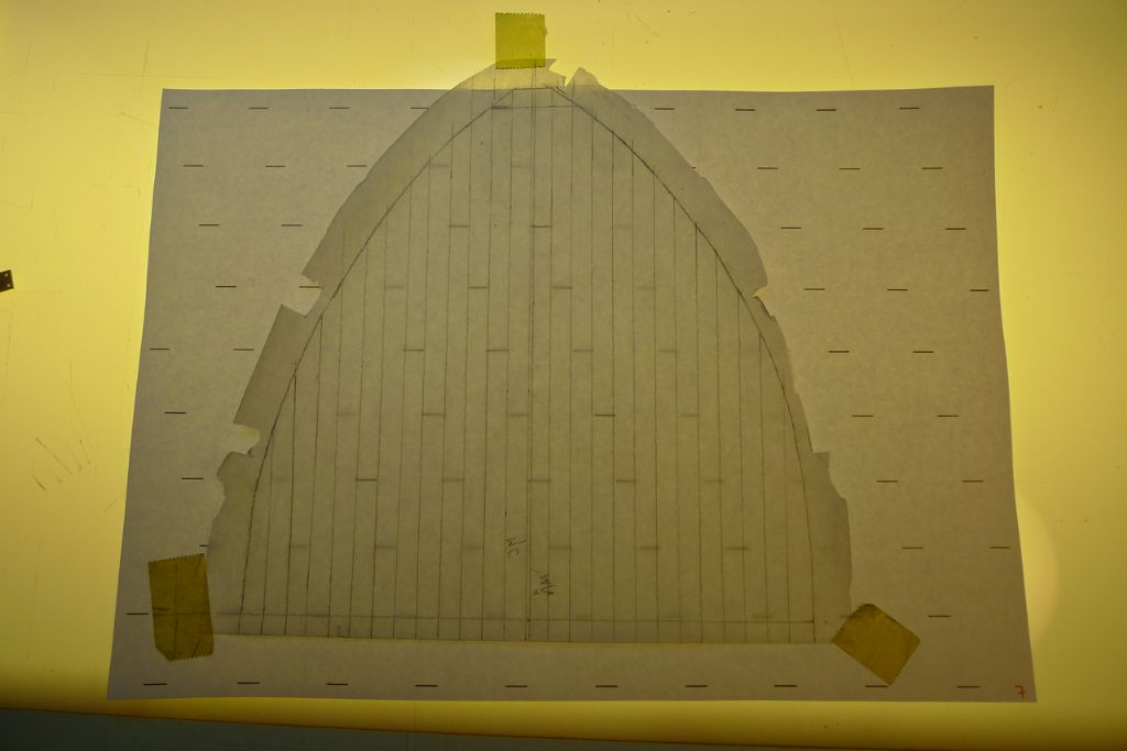
I therefore began by cutting out a piece of greaseproof paper to fit the entire foredeck. As I intended to use 1×7 mm maple strip for the planking, I plotted out fore-and-aft lines 14 mm apart using my short steel ruler that just happens to be 14 mm wide, each line thus representing a two plank width. At scale, 1×7 mm would correspond to planks approximately 1 inch thick and 6 inches wide.
After adding the intermediate fore-and-aft lines, I then carefully measured 12 mm (I think it was) from the inside edge of the bulwarks at a series of points all the way around the foredeck and then joined up the dots. This gave me the general outline of the area to be planked.
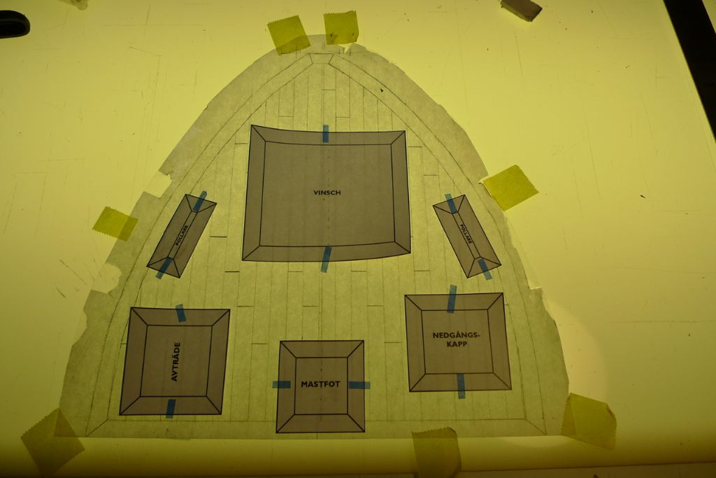
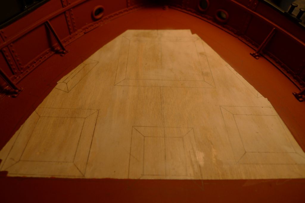
Next, I needed to decide on the butt shift system and pattern, and also on the basic plank length (i.e. the longest length of plank to be used). To help me decide on this, I used the computer to draw up a three shift butt line system for planks corresponding at scale to respetively five, six and seven feet.
My main worktop just happens to be an old drawing table that I managed to lay my hands on for the proverbial song-and-a-dance many years ago, when the Information Office of my then employer went fully digital and threw out all their old stuff. Among other things, this table has a built in light box under the glass table top, and this now came in very handy for seeing how the various butt shift patterns would look …
… in conjunction with the fittings and superstructures on the foredeck.
After shifting the various patterns about (the above photo shows the five foot-plank pattern), I finally plumped for a layout based on a three butt shift and six foot basic plank length. Six feet equals 76,2 mm in 1:24, so by rounding of ever so slightly to 76 mm, this gave me a distance between butts of 19 mm.
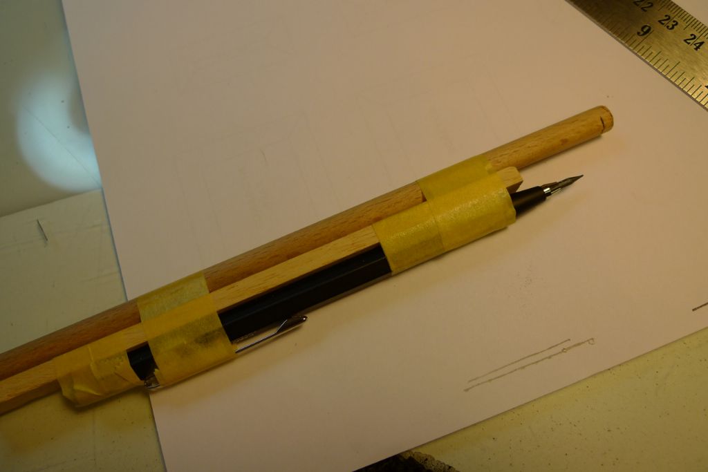
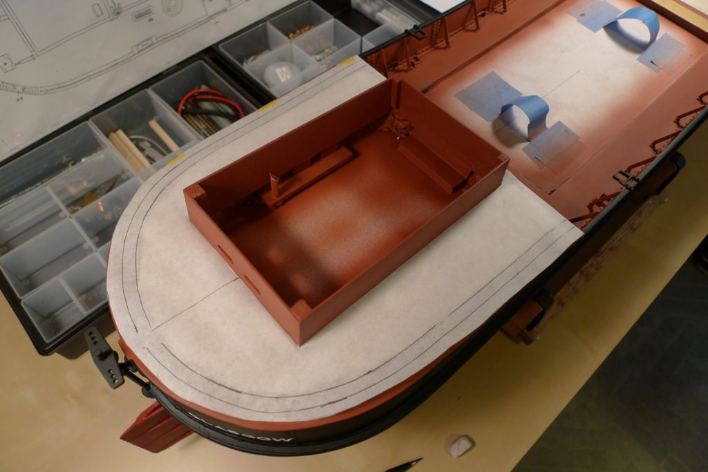
A similar proess was of course applied to the quarterdeck. To get the planking area outline, however, I instead taped a pencil to a length of dowel …
… and simply drew around the quartedeck, with the dowel sliding along the outside of the hull. For the inner line, a piece of 7 mm thick wood was simply added between the pencil and the dowel.
The finished drawings were then photocopied from the greaseproof paper to regular paper, cut out to shape and laid down onto the decks for a final check.
To be continued …
/Mattias
Edited By Banjoman on 17/11/2014 09:42:33
18 November 2014 at 12:21 #53681Banjoman
Participant@banjomanFor no particular reason, I started the planking process on the quarterdeck.
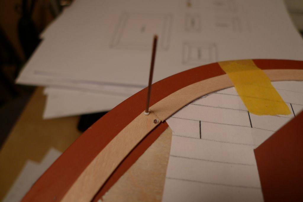
First up, the curved edge planking was made up. The paper pattern was glued to the back of a piece of 1 mm maple sheet, and the rough shapes cut out on the bandsaw …
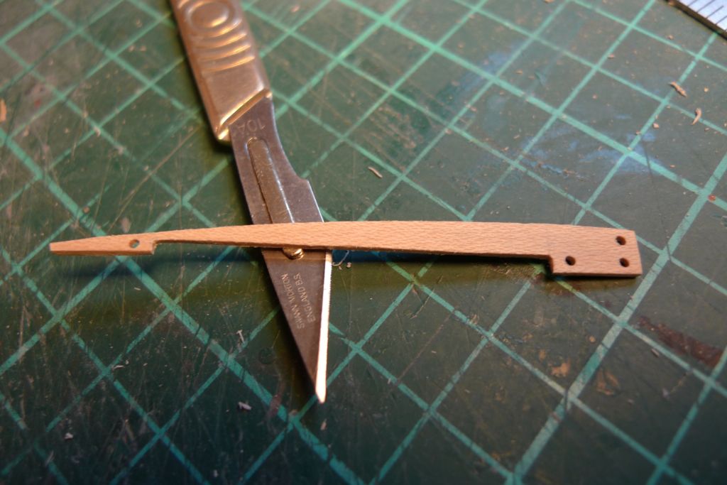
… and then trimmed to fit. The plank ends were marked out for dowel holes using a simple distance jig, 1 mm holes drilled and then filled with the same size walnut dowel.
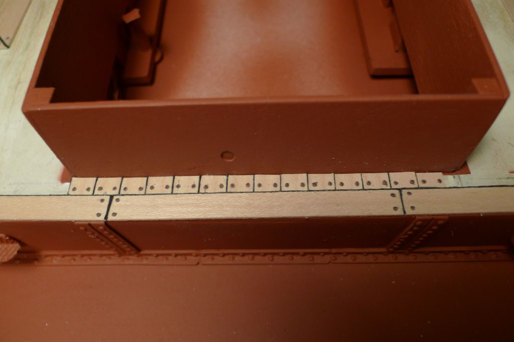
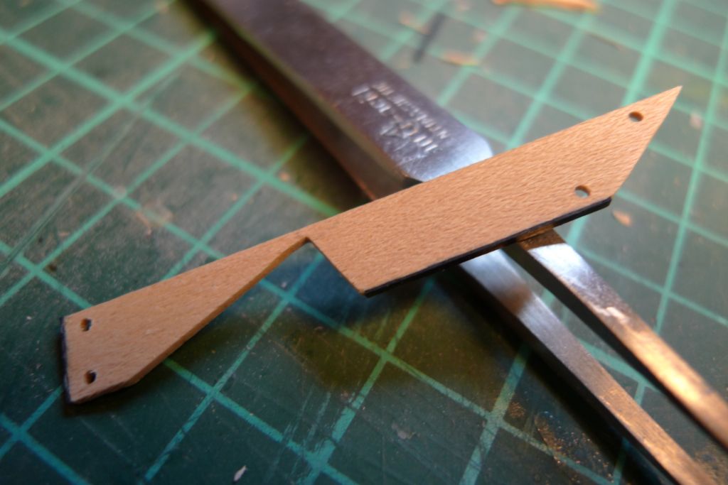
The plank frames to go under the bollards were also glued in place et this stage, as they form part of the edge planking.
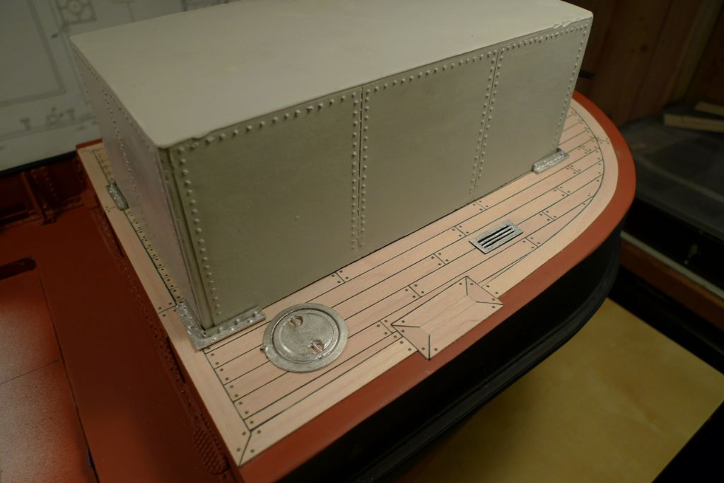
Once the edges were in place, planking proper could begin. For the seams, I decided after some off-model tests to go with black cartridge paper, which I think tends to look better at larger scales like 1:24.
It was fairly slow work cutting each plank to size and shape, drilling it for dowels and glueing it down …
… but after a couple of weeks …
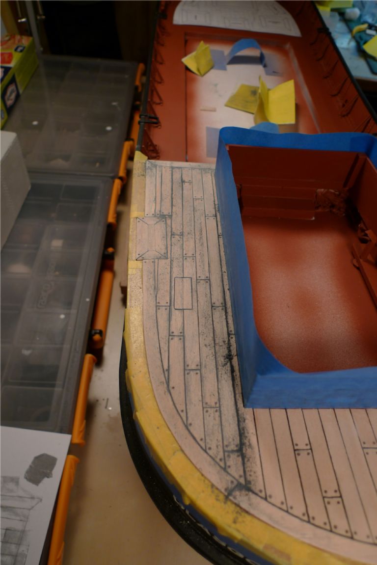
… it was all done, and sanding could begin! This is of course where cartridge paper shows its main drawback: plenty of black dust that at first gets into the wood surface …
… although perseverance with the sanding block soon had that particular issue sorted …
… and some of the white metal quarterdeck fittings could be dryfitted on the finished deck.
To be continued …
/Mattias
Edited By Banjoman on 18/11/2014 12:23:10
19 November 2014 at 08:56 #53694Banjoman
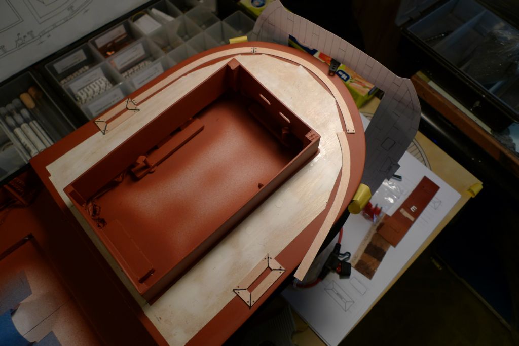
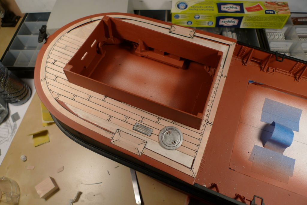
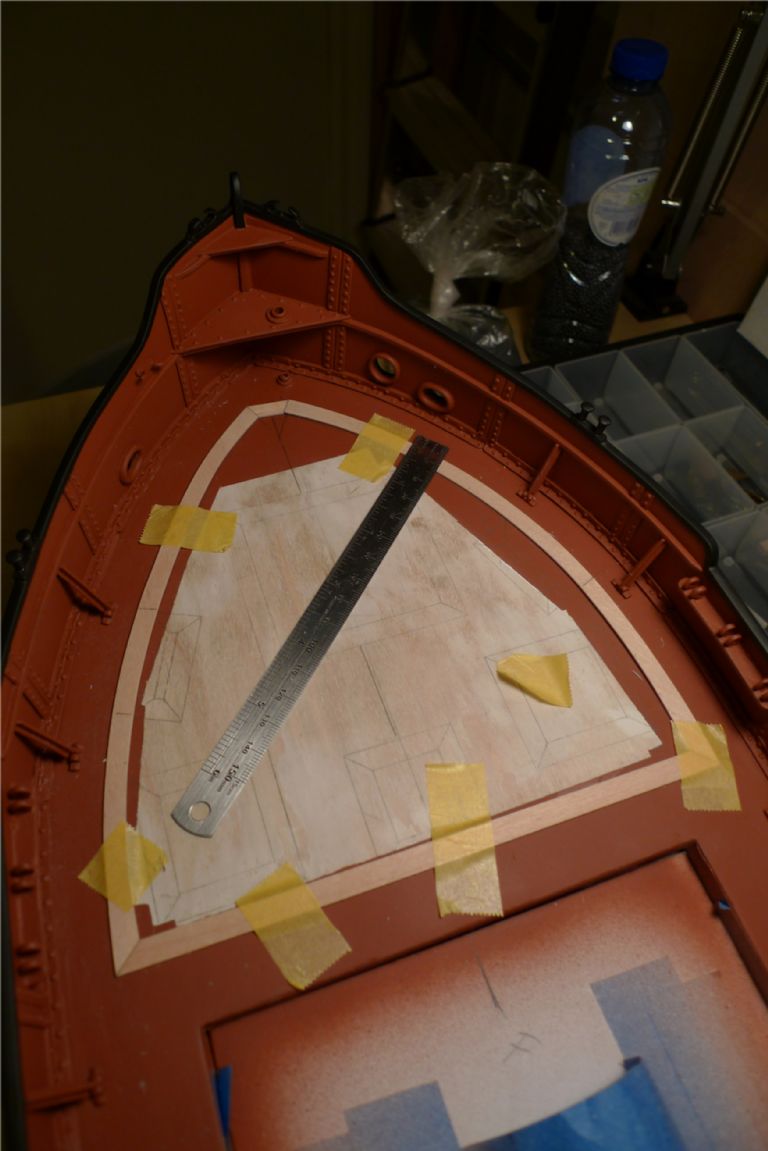
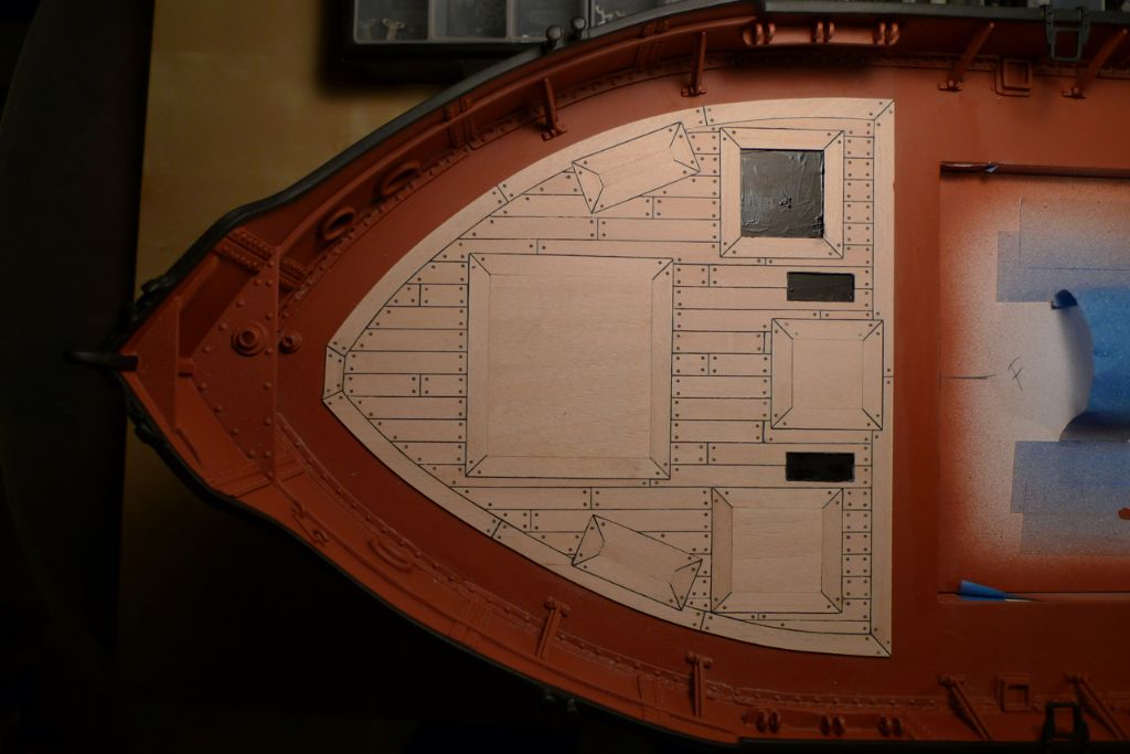
Participant@banjomanWith the quarterdeck planking finished, I moved on to the foredeck, first tracing the general layout onto the deck.
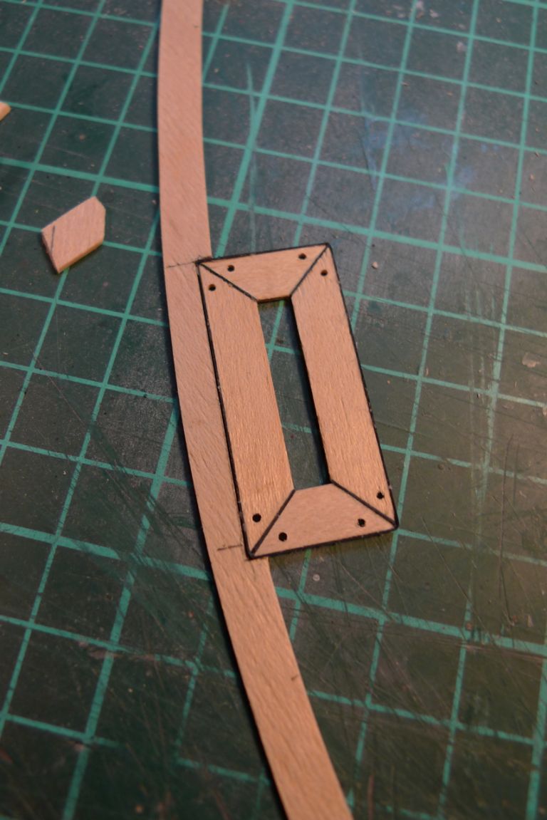
The edge planking was then cut out and trimmed to fit …
… again including the bollard underframings.
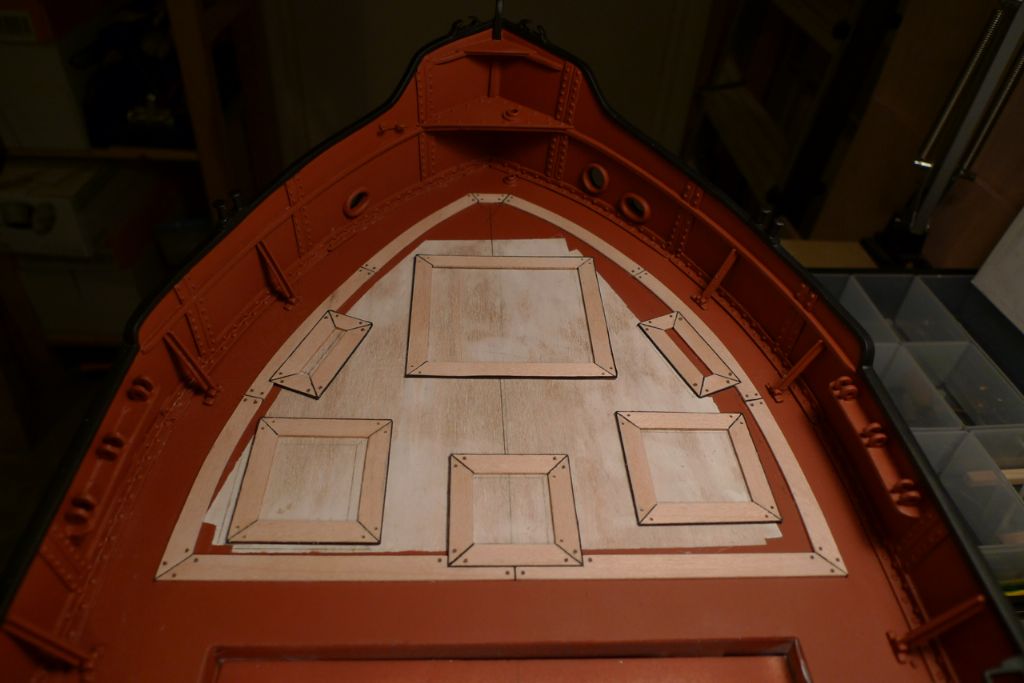
The rest of the underframes were then added where the winch, the lavatory, the mast surround and the companionway shelter were to go …
… although these were only glued down as planking progressed …
… in order that their exact locations could be guided by the positions of adjoining planks.
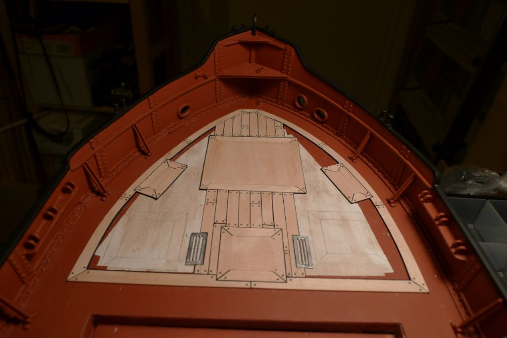
Some of the planks surrounding the underframes required fairly precise shaping …
… within fairly tight tolerances …
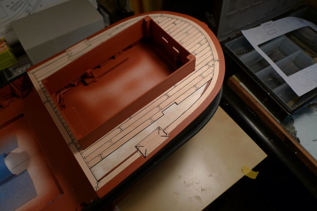
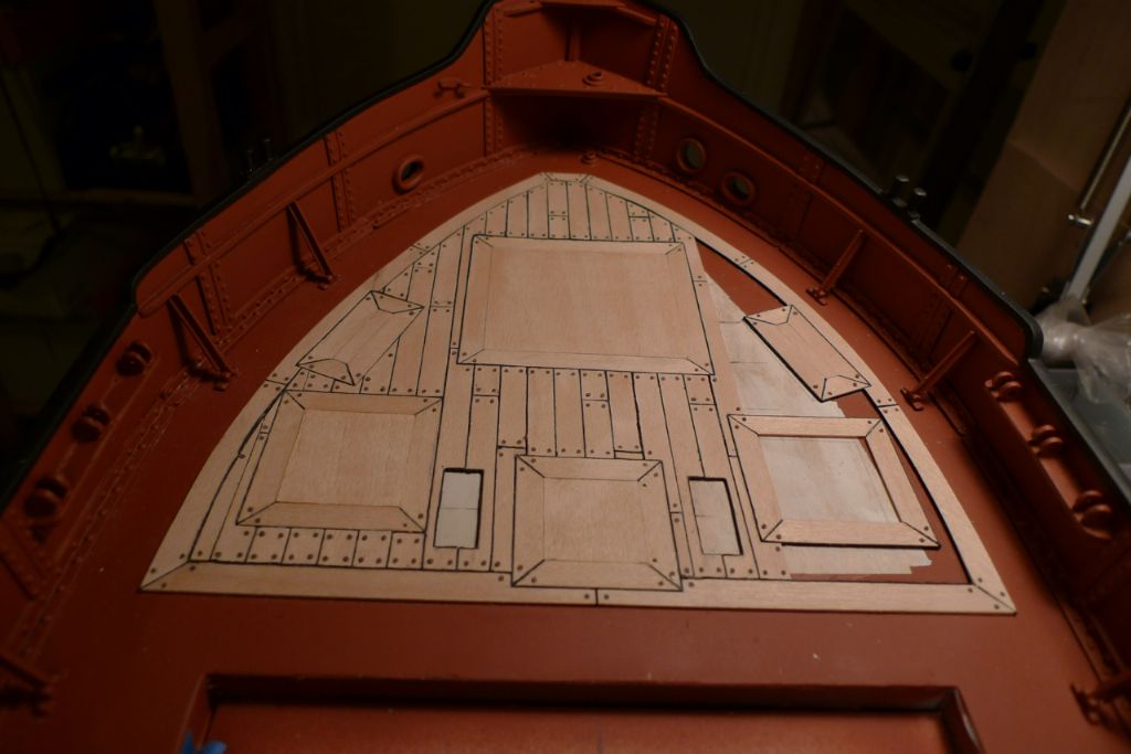
… but in the end I got there. I briefly considered opening up the deck below the companionway shelter, and putting a box underneath, to get a better feeling of depth if the shelter doors were to be opened, but in the end decided against it as being not really necessary while creating a potential problem with water ingress into the box when on the pond. Instead I simply painted the deck black here.
A careful look at the above photo, which is taken directly from above, will make quite clear, I think, what I've meant when I've previously said that the bows and foredeck are not symmetrical between the port and starboard sides.
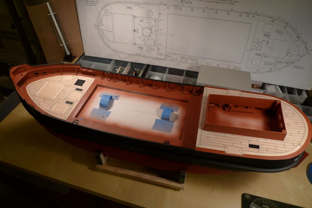
However, when looked at from most other angles, as for example in the photo below, I think I can say that the assymetry is not really something one notices, and that the compromise shapes used to some (and hopefully sufficient) extent camouflages this.
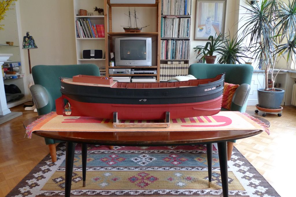
After finishing the deck planking, both the hull and the decks were given several coats of Vallejo Premium PU satin varnish, and the hull brought up into the appartment for some daylight photography.
To be continued …
/Mattias
Edited By Banjoman on 19/11/2014 09:00:43
19 November 2014 at 15:24 #53697 Paul TParticipant@pault84577
Hello Mattias
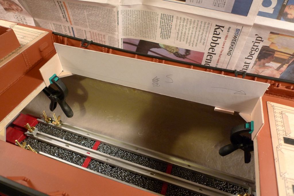
Your build has been an eye opener for me and I have been very impressed with your ballast solution and the ingenious track and clamp system.
The attention to fine detail certainly puts my building to shame and you should be very proud of your skill.
Thank you for sharing this with us
Paul
20 November 2014 at 09:40 #53708Banjoman
Participant@banjomanWarmest thanks, Paul, for your kind words of appreciation! The joy of these kind of fora does, I would say, lay not least in the fact that they allow us all to share thoughts and ideas and, not least, our passion for and enjoyment of the lovely hobby that is model boat building.
Sometimes, however, basic honesty requires that we also share our failures, and I am now getting to precislely such a moment in the Eilean Mòr build, where I was once more defeated by my old arch-nemesis, the evil Dr Impatience!
Having brought the finished hull up into the appartment for some daylight photography, as previously mentioned, I found myself thinking "hmm … it would be nice, wouldn't it, to see how she now sits in tha water", so off I went to fill up the bathtub.
She did indeed sit most nicely in the water, but alack and alas! When I lifted her out again, I was met with this rather horrible sight:
"Oh, bother!", I said. Possibly even "fudge!". Or summat along those lines, anyway. Lumme, did I kick meself, and hard!
I know perfectly well that acrylic paints are devious in the sense that they dry from the outside in, and that they can thus appear quite dry and hard on top but may still be sitting on an inner layer of not yet fully cured paint.
I also knew full well that the particular paits and varnishes that I use will be surface dry within half and hour, tops, usually fairly well cured after three to four days but fully hardened only after a week or two. The varnish I had recently put on was only three days old here, and to make matters worse I had out of habit filled the bath without turning the thermostatic taps to cold only. I had in other words run a hot (i.e. 38º C) bath!
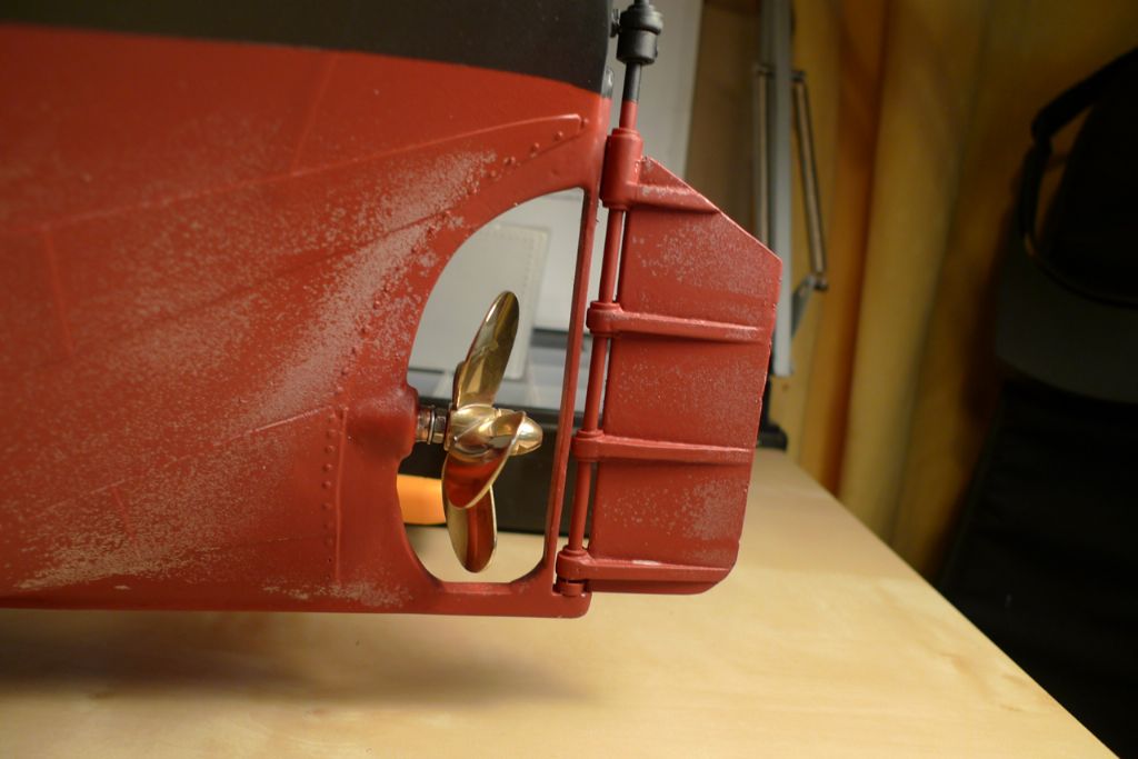
Together, the effect of recent varnish and warm water made the varnish detach from the underlying paint in patches all over the lower half of the hull, and to come off in strips.
The good news, though, was that the actual paint was completely unaffected! This was of course by now over a month old, and thus fully cured. Taking heart from this, I stopped berating myself quite so viciously, and instead settled down to making good the damage.
First, I pulled and rubbed off the varnish weherever it had come loose, using first the adge of a piece of sandpaper to get in under the varnish, and then just my finger tips to rub it loose until it could be pulled off.
Once all the damaged varnish had been removed in this way (and I had built up some lovely blisters on my fingertips, too), I got out the methylated spirits and some cotton buds. Using these very carefully (think "arts restorer on the Antiques Roadshow"
 , I gradually evened out all the edges between any remaining spots of varnish and the underlying paintwork. The methylated spirits dissolves the paint, and thus lets one "melt" together the different layers, removing any differences in level in the process …
… and after masking off the top half, a couple of coats of freash red paint could be applied.
To be continued …
/Mattias
20 November 2014 at 09:41 #53709Banjoman
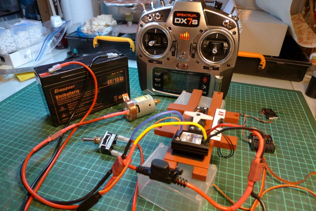
Participant@banjomanWhile the new paint was drying, I kept myself busy by completing the radio installation. With Dave Milbourns excellent article on electronics as a guide, I added a 15A main switch and a 10A fuse in the positive line of the main circuit.
I also measured the fore-and-aft sheer of the deck alongside the main hatch opening by offering up a piece of cardboard to the edges and then drawing along the deck with a short piece of pencil lead …
… and then began constructing the main hatch coamings.
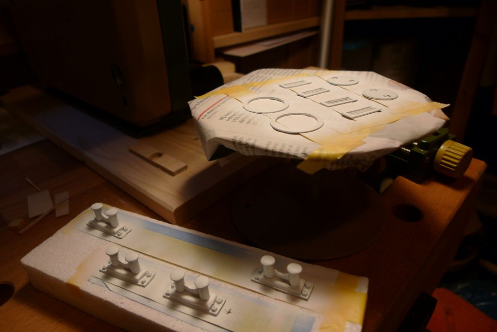
As I had the airbrush out and the paint box set up, I also primed and painted some of the white metal deck fittings …
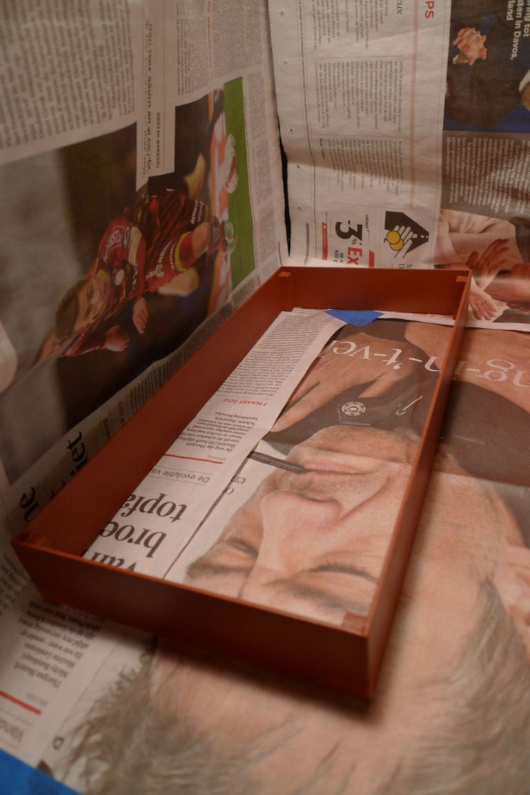
… as well as the coamings …
… then touched up the bits of black paint on the hull that had also been affectd by the varnish disaster …
and finally applied a couple of coats of varnish to the hull. All in all, my own utter and complete stupidity cost me two weeks of redoing the paint job, but at least and at last I was back where I'd been (and I had the hatch coamings ready, too)!

To be continued …
/Mattias
Edited By Banjoman on 20/11/2014 09:43:01
20 November 2014 at 11:15 #53711 Colin BishopModerator@colinbishop34627
Some lovely work there Mattias, the mishap with the varnish must have been a nasty shock though! Glad you managed to retrieve the situation. I have found that acrylic varnishes often seem to just form a film on the underlying surface without properly bonding to it so that if they become abraded they are prone to peel off. I prefer to use solvent based polyurethane varnish myself as this does seem to stick to almost anything without damaging the underlying coat.
Colin
20 November 2014 at 11:55 #53714Banjoman
Participant@banjomanThanks Colin! Indeed, the moment of discovery was not my most joyous expereience ever, but thankfully and to my unending relief it turned out alright in the end!
I also took away some new (and, in the final analysis, not too hard bought) knowledge, namely (and as you say) that acrylic varnishes are not really the feline's nightwear. As the further build will demonstrate, the Vallejo RC Premium clear gloss varnish is very useful on bare or stained wood, so that is a product with which I intend to stick; likewise, the satin variety is usable directly on wood, but not really to be trusted on painted surfaces.
I had been looking at the possibility of using something solvent-based, like for example the Inspire 2K-varnish from Specialist Paints (**LINK**), but in the end did not quite dare to attempt it, mainy because I'm worried about airbrushing or spraying solvent based stuff in my limited space/no mechanical ventilation workshop.
I do of course always wear a proper half mask — a Sundström SR100 (**LINK**) with a P3 filter — even when spraying "only" acrylics, as I do not wish to slowly but surely paint the inside of my lungs together with the outside of my model, and could, I suppose, add an appropriate filter (http://www.srsafety.com/products/filter) against the solvent fumes, but I've still hesitated. Sooner or later, though, I think I shall in any case have to sort out some sort of extraction system, but until then … 'tis hesitant that I am, me!
By the way, which solvent-based PU varnish(es) do you use?
Edited By Banjoman on 20/11/2014 11:57:03
21 November 2014 at 09:42 #53740Banjoman
Participant@banjomanThe main hatch coming was then glued in place …
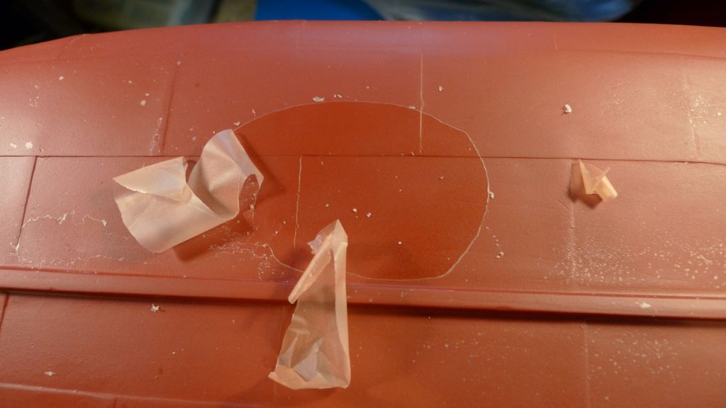
… and I moved on to the matter of opening up holes in the quarterdeck for the coal bunker scuttles.
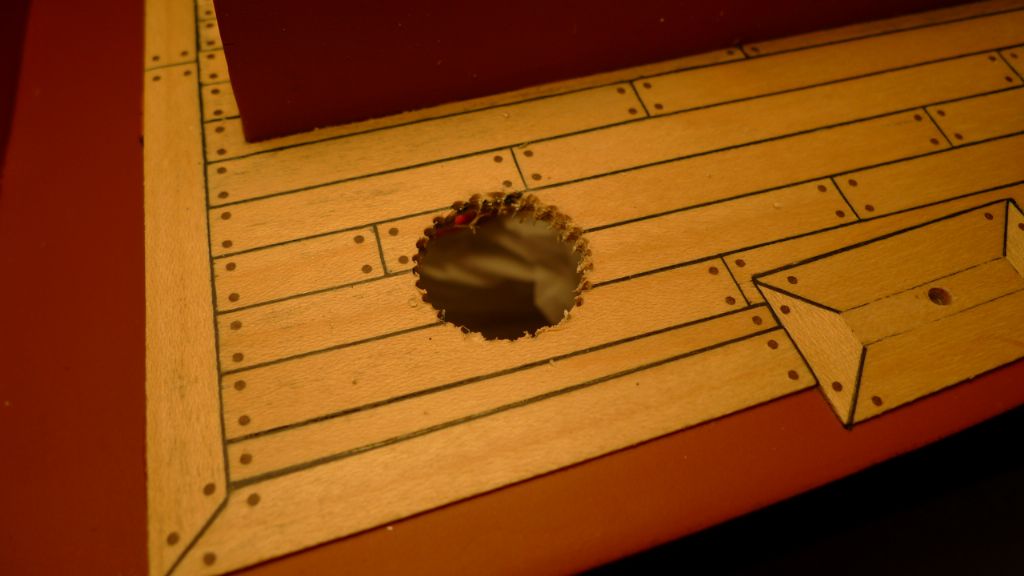
I had made a couple of tests just drilling with an 20 mm spade bit through a similar plywood-and-plankning sandwich made up from some offcasts; however the results in terms of splintering were quite horrendous, and the thought rapidly abandoned.
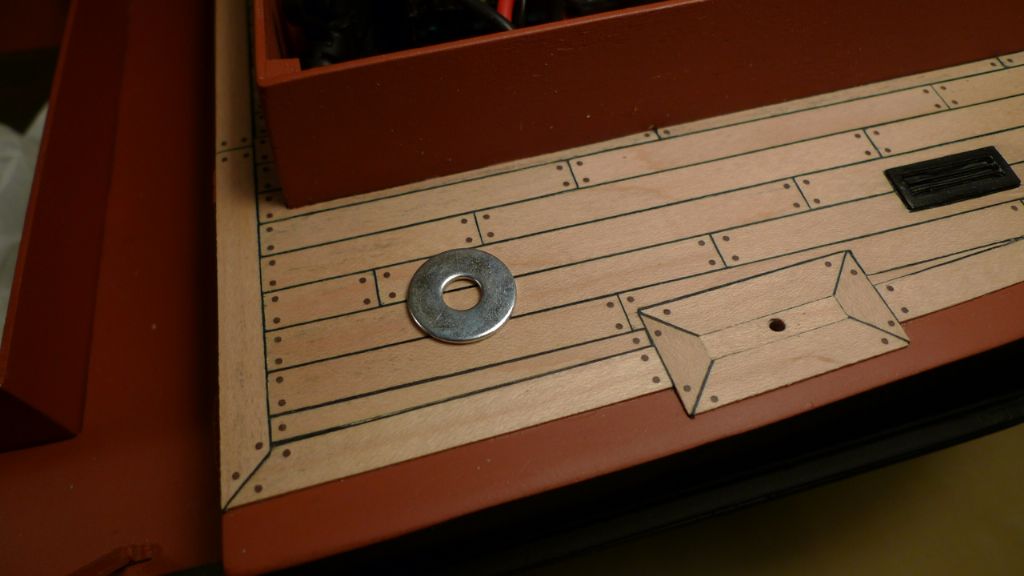
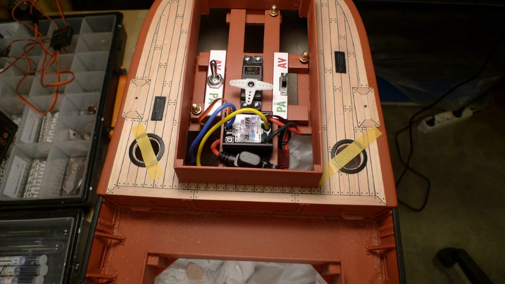
Instead, I hit upon the idea of using a couple of suitable size steel washers. These were carefully positioned on the deck, and some thin CA applied to the inner edge of the washer to be pulled in under it by capillary force.
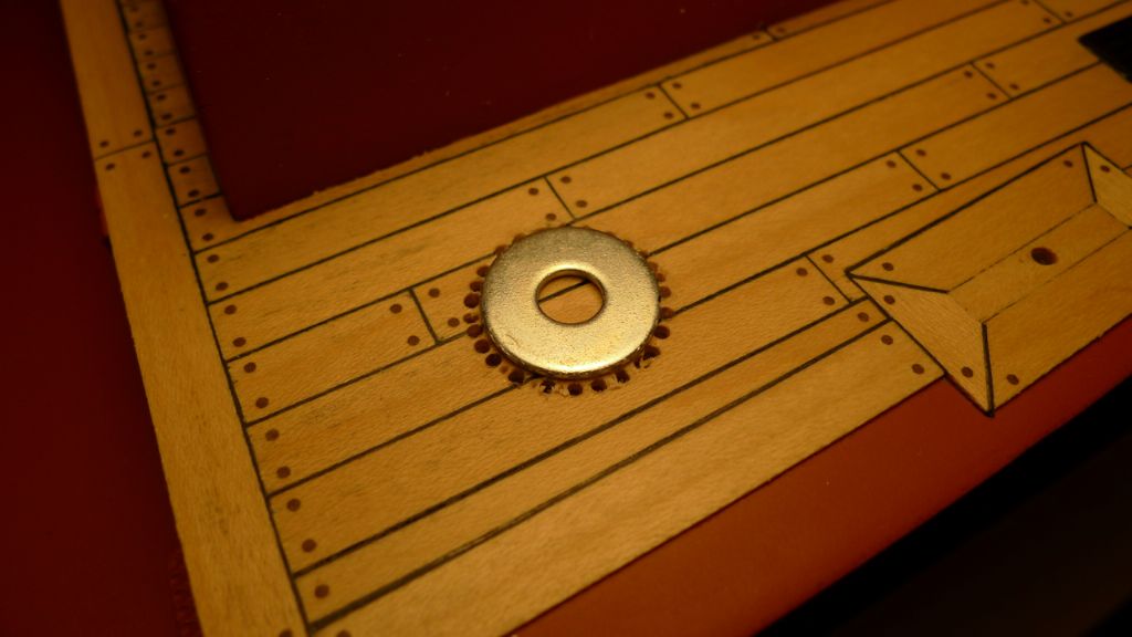
This fixed the washers solidly in place, which let them serve as reliable chain drilling guides.
After chain drilling it was a dodlle to cut through the final strands of wood with a scalpel´, leaving a nice, round hole as result that needed only some minor clean-up with a sanding drum in the Dremel.
The scuttle surrounds were then positioned and glued in place, again with thin CA and capillary force …
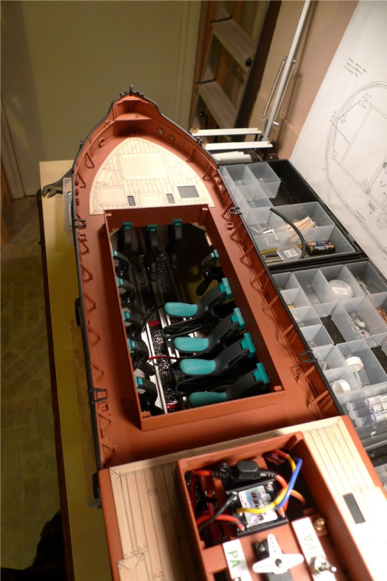
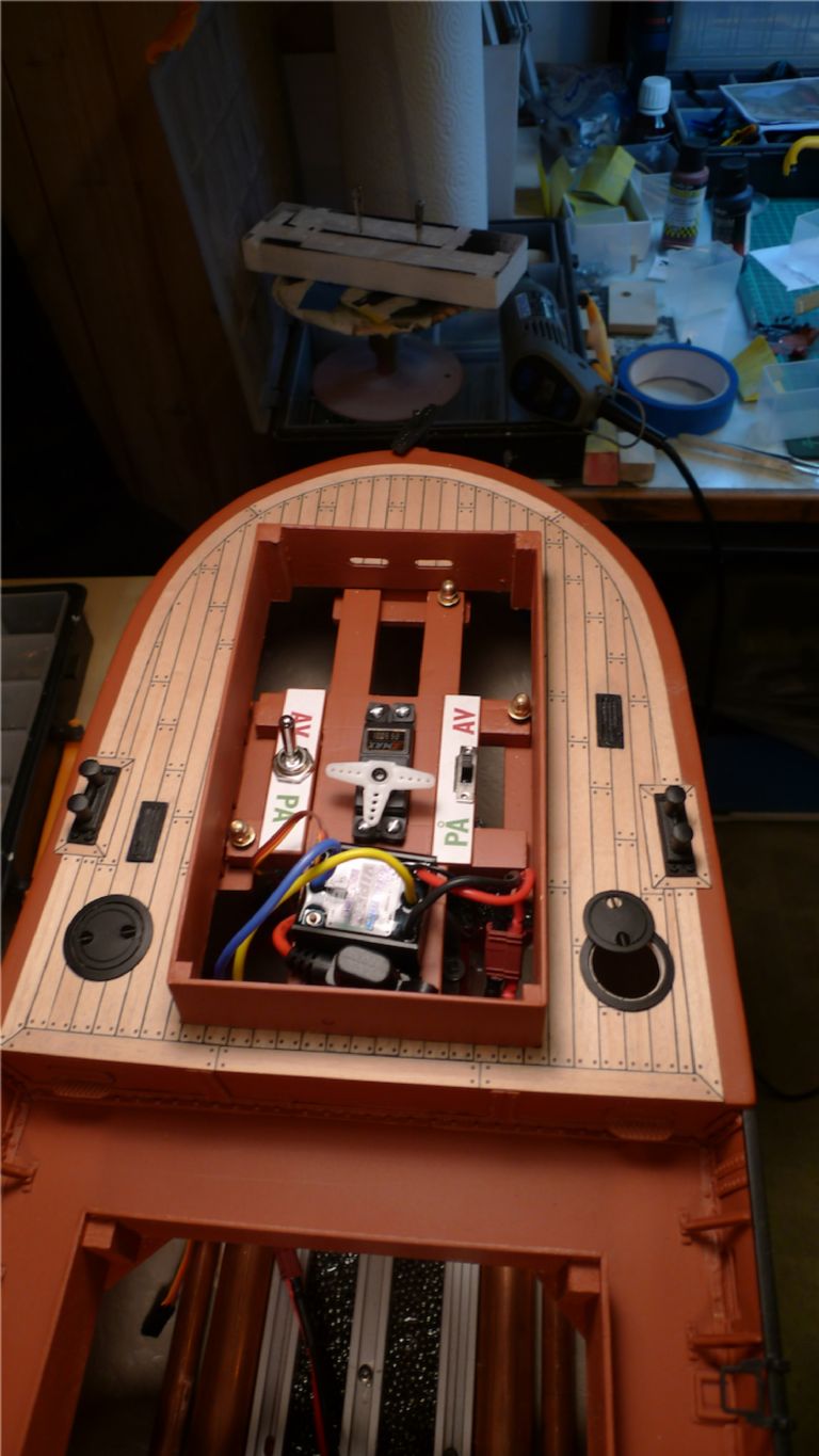
… after which the Dremel sanding drum was once more brought into play until just enough of an edge was left within the scuttle surrounds to rest the covers on. This phoot, by the way, also shows the final positioning of the rudder servo, ESC, fuse holder and on/off switches for the driveline and r/x.
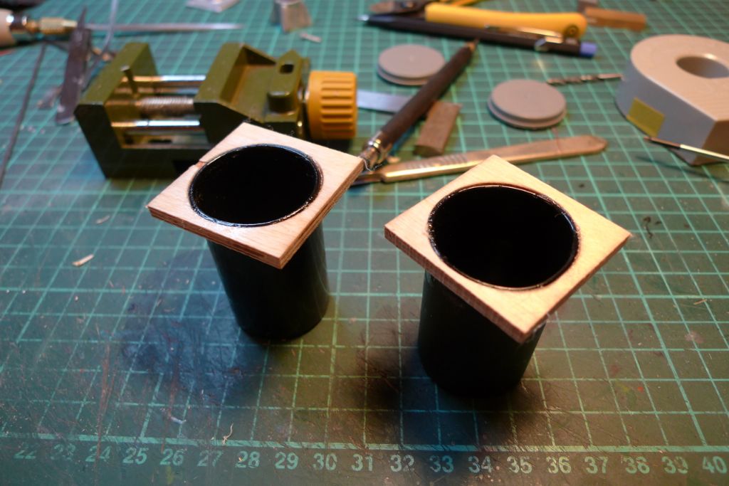
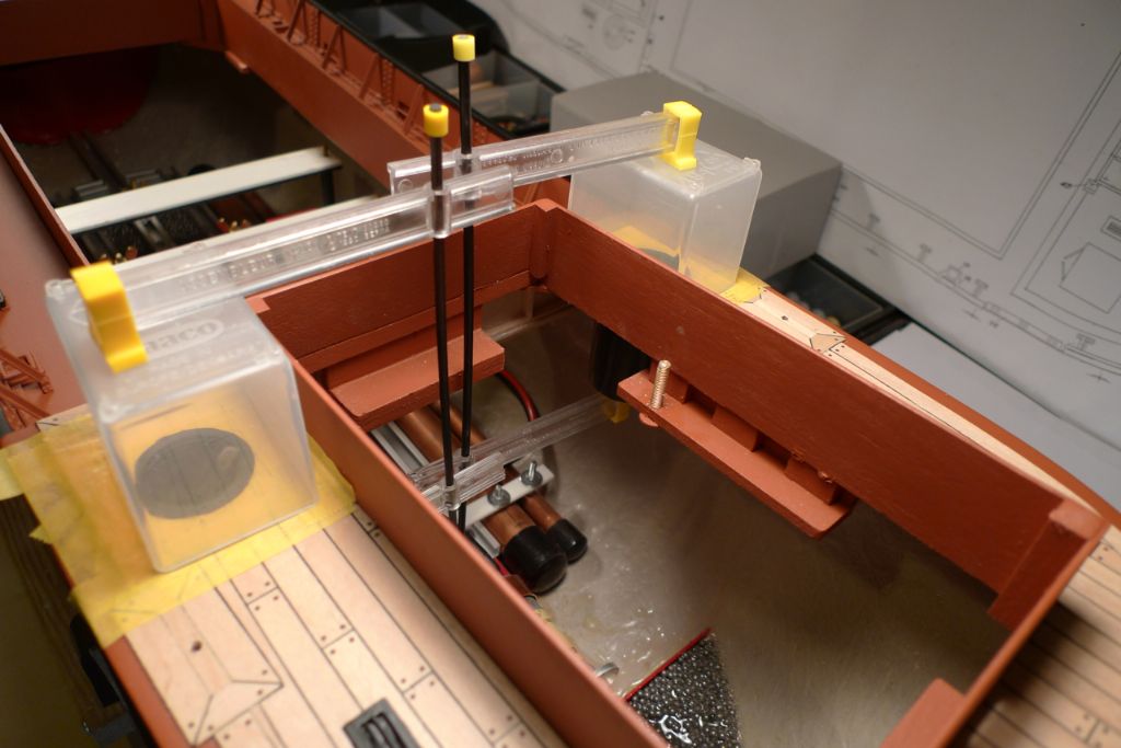
Plywood collars where then epoxied to a couple of old film cans …
… which were then glued in place under the bunker scuttles.
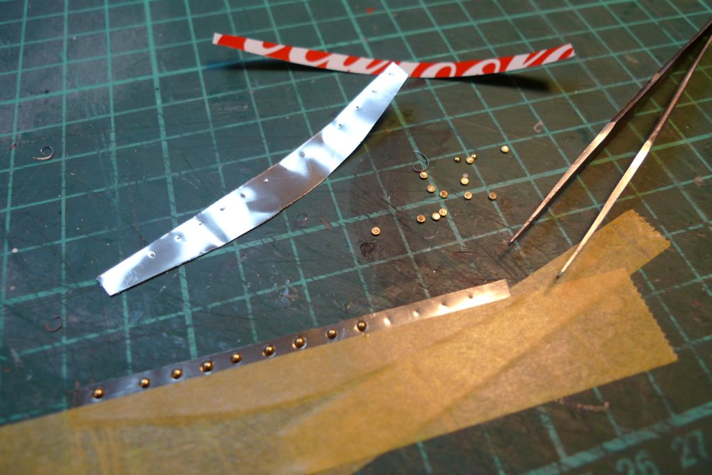
To finish off the scuttle openings, I cut off two strips of aluminium from a soft drinks can, lightly indented the upper edge and glued on some round brass nail heads to simulate rivets.
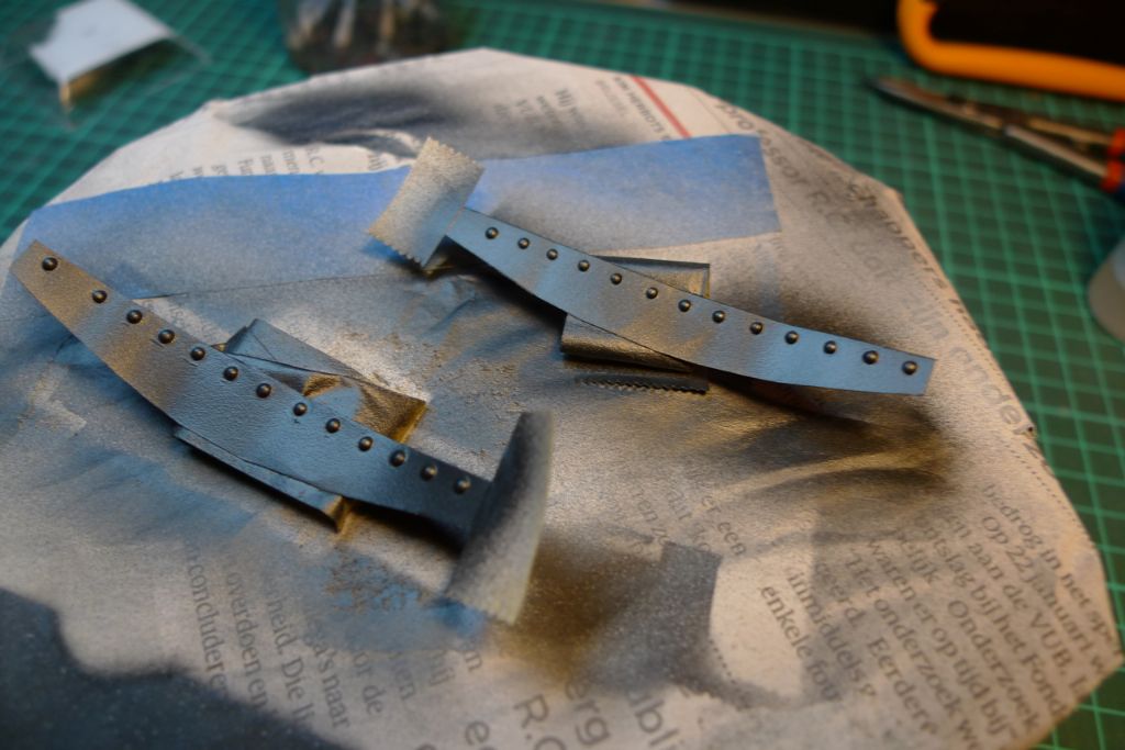
These strips were then painted metallic black …
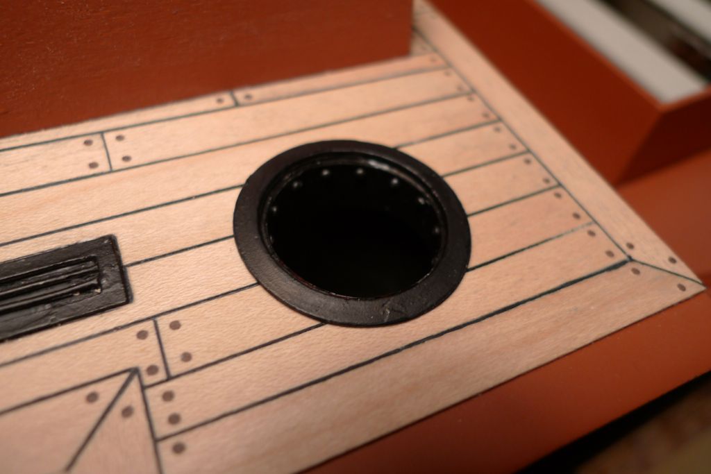
… and glued in place on the inside edges of the scuttle holes, to form a sort of short funnel into the (supposed) coal bunkers. I have no idea how true to real life this last bit of additional detail is, but I rather like it because it (a) hides the plywood-and-planking edge of the deck material (which I think would look both too thick and too woody), and (b) makes the scuttle openings look "engineered" or "made to a purpose" and also just simply that little bit more detailed.
To be continued …
/Mattias
21 November 2014 at 10:21 #53742Dave Milbourn
Participant@davemilbourn48782Matthias
I'm curious to know how you managed to get the black caulking effect between the planks. I've used soft pencil before now, but it seems to disappear as soon as you unfold a piece of abrasive paper anywhere near it. Do tell!
Dave M
21 November 2014 at 10:44 #53743 Colin BishopModerator@colinbishop34627
Ronseal PU varnishes are good:
Also Rustins do similar products:
Although intended for interior use that is only because they do not contain UV filters. they are fine for model boats and can be thinned to any desired extent for spraying.
It's best not to use the exterior PU varnishes as the UV filters give them a slightly yellowish tint which shows up over light colours.
Colin
21 November 2014 at 10:53 #53744Banjoman
Participant@banjomanHello Dave,
The caulking was made using black cartridge paper, approximately 0.225 mm thick, which was cut into thin strips and glued onto the plank edges using the same water resistant PVA glue with which the planking was glued down.
The advantages of the paper method at larger scales are several. At 1:24 for example, a thickness of 0.225 mm equals 5.4 mm at full size, which I think is quite reasonable and even more realistic than the thinner seams one gets by simply colouring the plank edges. Likewise, the paper almost functions like a real caulking. Not in the "making watertight" sense, obviously (duh!), but by evening out and filling in any minor roughnessess along the plank edges, thus creating prettier caulking lines. And because the strip covers the whole plank edge, one can sand away to one's hearts content, and as long as there is still a thickness of plank left there will also be caulking showing up!
There are two (minor, but still) disadvantages, too: it takes longer to do, because each strip of paper needs to be cut, trimmed to size and glued in place, and when sanding down, one intially gets a lot of black paper dust that will find its way into the grain of the wood, which then will need a bit more sanding than would otherwise have been the case. However, I quite like the method!
The only really tricky bit for me was getting hold of good quality black cartridge paper! I eventually found some in an artist's supply shop on King's Road in London during a visit there last year. The thing to look for is a carton that is both hard and thin enough — I had made some tests using regular 280 gr/m2 heavy black paper, and found this too soft to sand well. Cartridge paper and similar paper qualities tend to be more heavilly glued and pressed, which gives a stronger edge to the paper and it therefore sands better.
21 November 2014 at 11:41 #53747Banjoman
Participant@banjomanThank you very much indeed, Colin! If (when) I dare go down the solvent-based route, I will remember these tips! I'm not sure the exact brands will be available this side of the Channel, but similar products will, I'm sure, exist.
Oh, and about the cartridge paper method for caulking, I quite forgot to mention that I picked up the idea from an article in Model Boats a few years ago. I can't quite recall neither when nor what the build was, but I do know that on reading it I said to myself "when found, make a note of!" …
/Mattias
21 November 2014 at 12:14 #53749Dave Milbourn
Participant@davemilbourn48782Many thanks, Matthias. It's my custom to use thin veneer to simulate planking so sticking cartridge paper to the edge of that (0.8mm) might be a bit interesting!
Dave M21 November 2014 at 12:38 #53750Banjoman
Participant@banjomanYou're welcome, Dave! I used 1.0 mm thick (or thin
 ) maple strip wood for this planking job, so I quite understand what you mean by "interesting" …
It was a tad fiddly, but not really that hard to do. I first cut just over 1 mm wide strips of cartridge paper (I happen to have a Rotatrim rotary trimmer [**LINK**] from another context that came in rather handy for this job, but a steel-ruler-and-scalpel set up will work perfectly well, too). The butt ends had the paper glued on before the planks went on the boat, but for the longer runs I first glued down a complete planking row before adding a single, long strip of paper along the entire side of the row. The next row of planks could then be glued down, well pushed up against the paper caulking of the previous row.
Where the shapes became more complicated, around the underframings and suchlike, the approach varied, and paper was applied on or off the ship to suit the circumstances of each location.
As I said, a tad fiddly, and I don't know that I'd use this technique in any of the smaller scales, but here it worked quite well.
Of course the paper strips can be a bit wider than the planking material anyway, and the excess simply trimmed away before sanding down to an even and smooth finish.
/Mattias
24 November 2014 at 10:24 #53805Banjoman
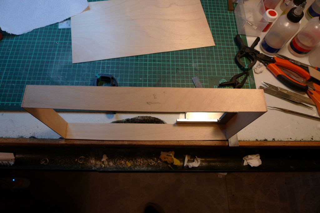
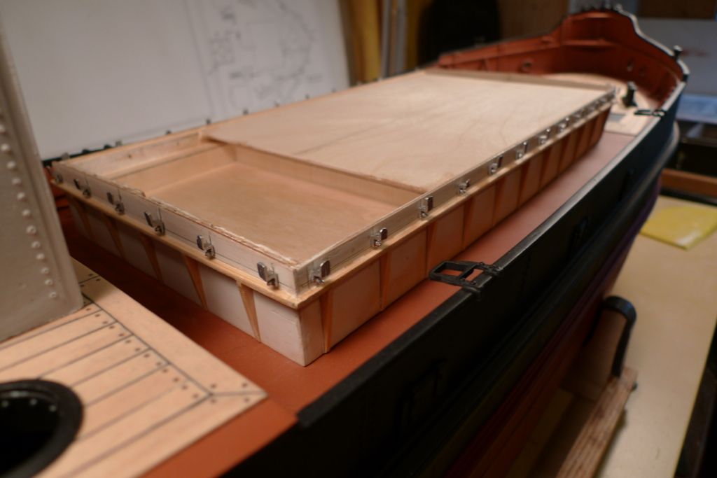
Participant@banjomanWith the main hatch coaming in place, I turned my attention to the hatch box. The deck sheer that I had previously plotted onto cardboard was traced onto the plywood sides …
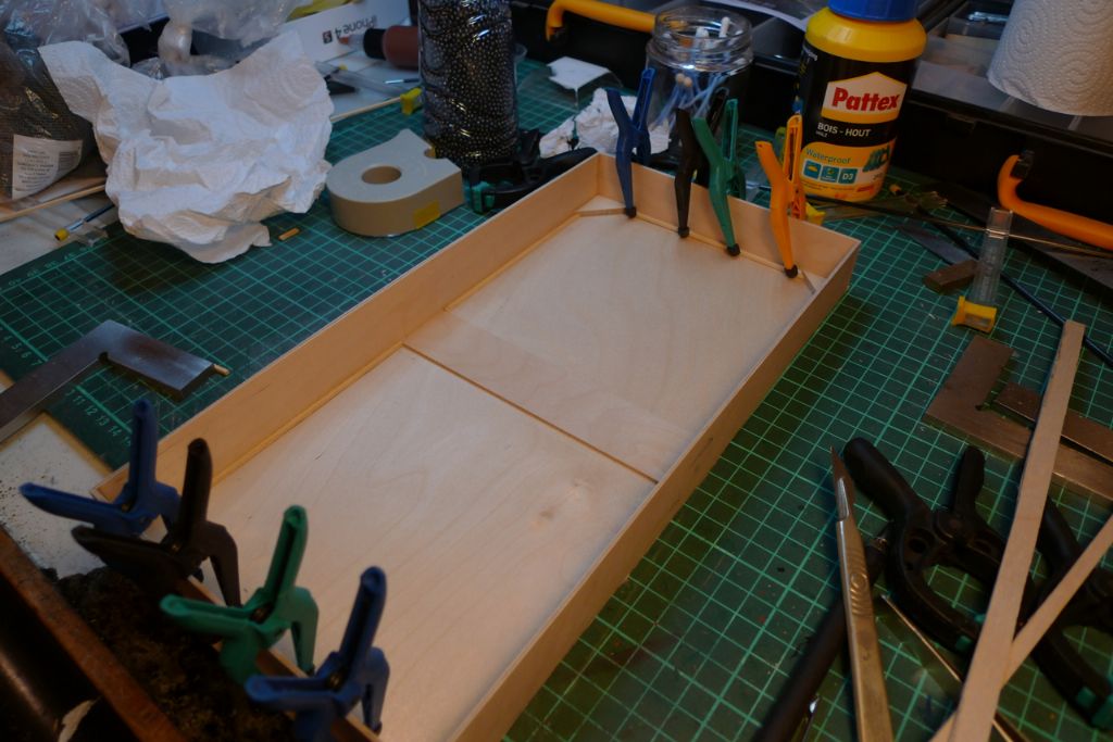
… the box lid was glued on, and reinforced on the underside …
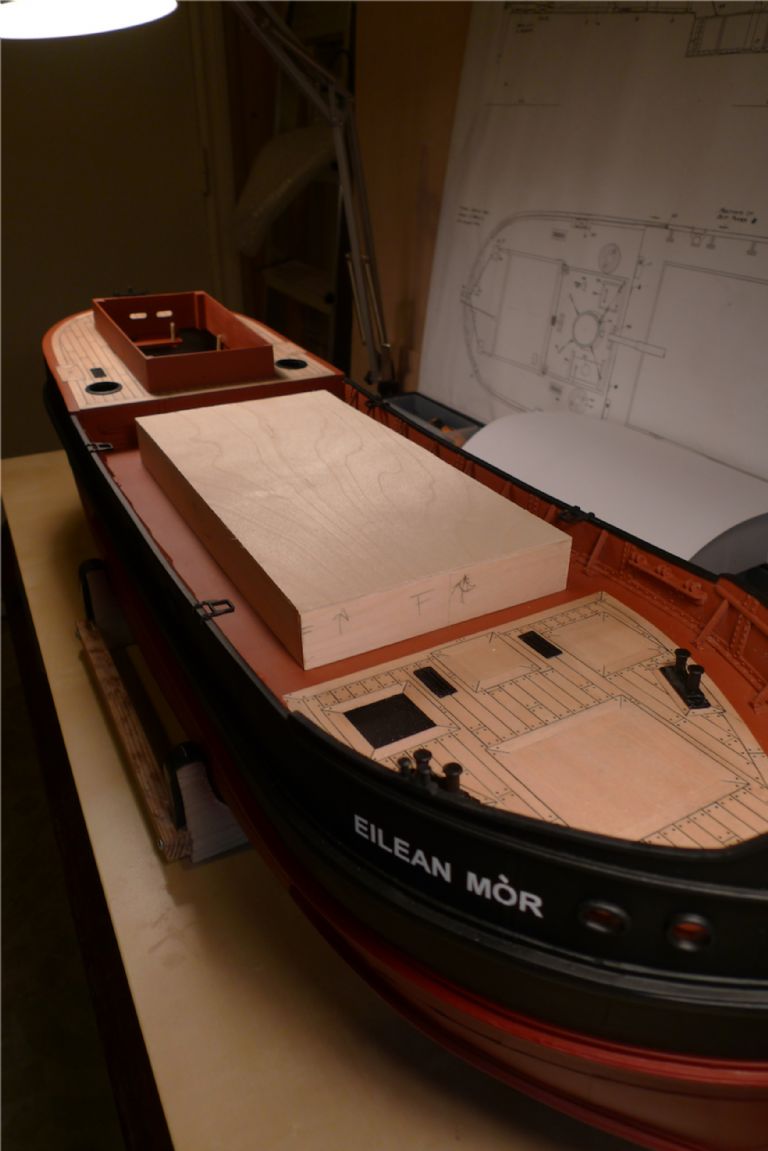
and the lower edges of the box carefully trimmed and sanded until there was a nice, tight fit between the box and the deck all the way around.
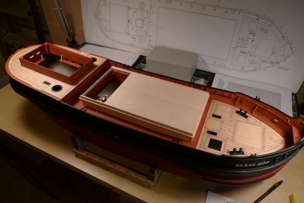
As I intended to go with the suggestion in the instructions to leave a part of the hatch "open" with some of the (supposed) cargo showing (from what I've seen of similar builds, this approach seems pretty much de rigeur for model Puffers, and who am I to question tradition?!
 ) the aftermost part of the box lid was then cut away.
A collar was then made up from plywood, to sit atop the coaming in such a way that the recess for the fake cargo could be made a bit deeper than would otherwise have been possible.
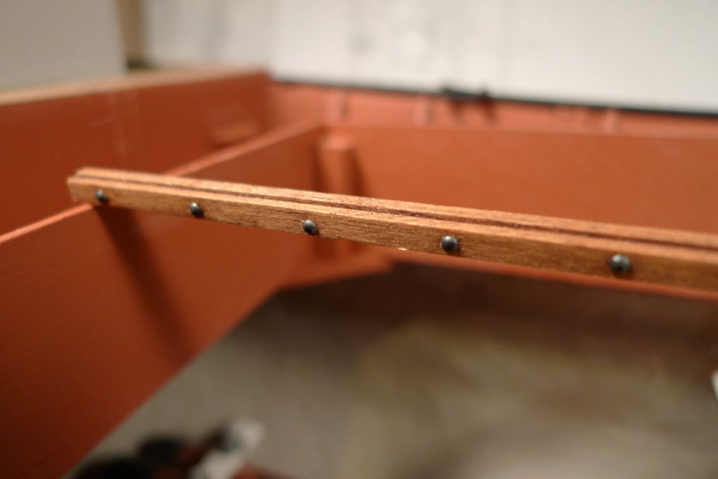
At this stage I also made up the strongback beam to sit fore-and-aft across the center of the hatch. To make it look a bit more "made", but also in order to create a ridge against which the hatch cover boards could rest, it was constructed from three pieces of strip wood, and a series of round nail heads added at regular intervals to simulate reinforcements.
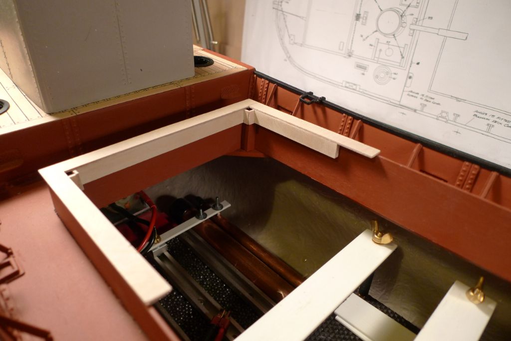
I then added a crossbeam at the end of the hatch opening, and two more longitudinal beams for the hachboards to rest upon.
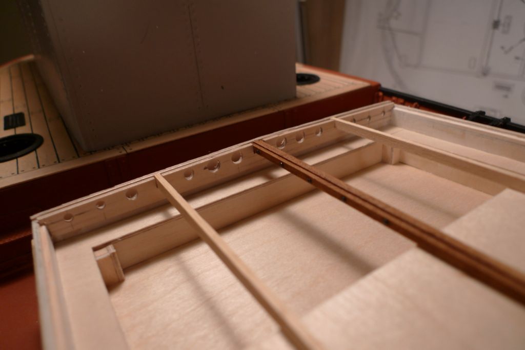
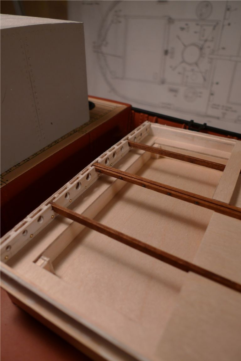
The end crossbeam was further detailed by drilling a series of lightening holes through it, had some round nail head riveting added, and was given cutouts for the longitudinal beams to rest in.
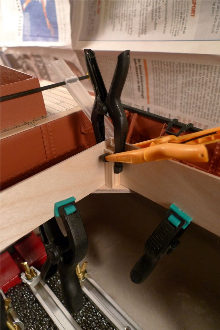
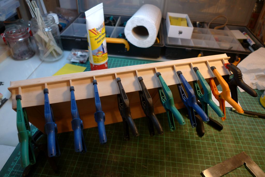
The entire outside of the box was given a couple of very thin coats of standard filler, which was sanded down before horizontal and vertical reinforcements were glued onto the outside.
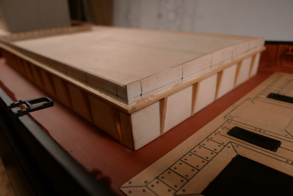
The verticals where then planed down to a triangular shape, and the whole works given a few coats of sanding filler, after which the upper sides were measured and drilled to take the wedge cleats.
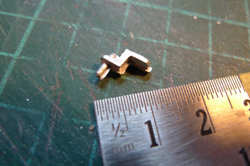
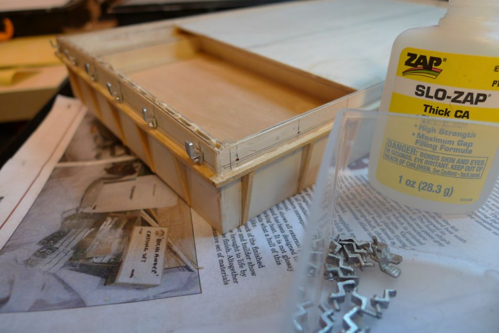
These wedge cleats, alas!, were among the less well cast parts of the kit — clearly the two halves of the casting form had been misaligned — and thus required some serious trimming and clean up; a bit of a chore given that 36 were needed …
However, in the end I got them to where they would do, and they were duly glued on …
… after which the finished hatch box, prior to painting, looked like this
To be continued …
/Mattias
Edited By Banjoman on 24/11/2014 10:29:21
24 November 2014 at 10:56 #53806IAN_I
Participant@ian_iGood Day…Mattias..
I am still enjoying the Build review, it is looking great.
You must be very pleased.
Best regards,
Ian
25 November 2014 at 07:50 #53816Banjoman
Participant@banjomanThank you very much, Ian! Yes, I will freely admit to being not too unhappy with the final results of this build …

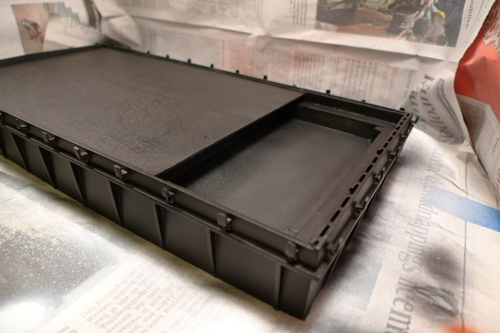
Anyway, the finished hatch box was painted black …
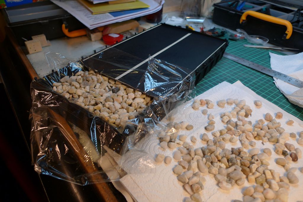
… and a cargo of coal was prepared. The kit came with a few lumps of real coal; however, as I suspected that the amount included would not be quite enough, I decided to first put in a bottom layer of painted gravel. I thus grabbed a couple of handfuls out of the bag of gravel that we use for putting on top of flower pots, washed and dried it and measured out a suitable amount to cover the bottom of the cargo tray in the hatch.
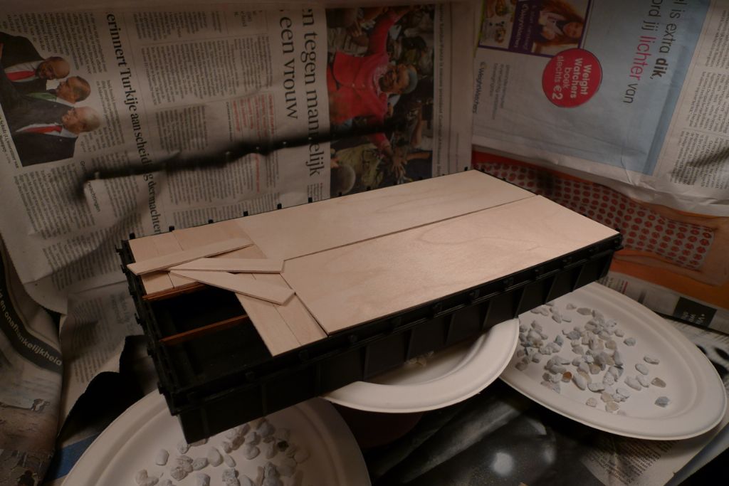
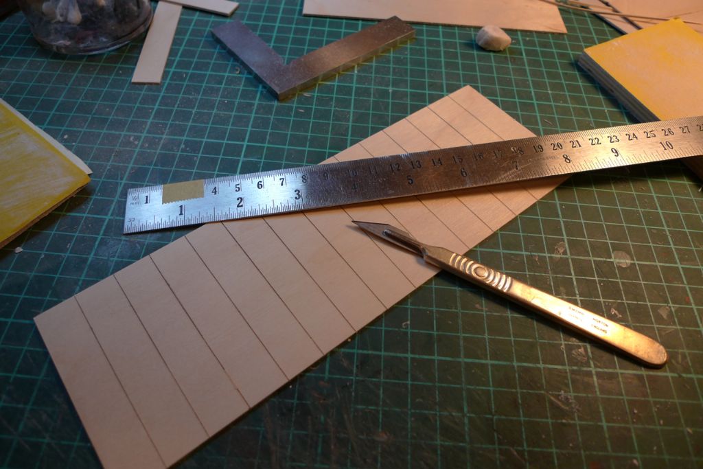
I also began preparing the hatch covers. As the main part of the hatch would also be covered by a tarpaulin, I chose not to cut out separate boards to go all the way …
… but instead just scored longer pieces of plywood.
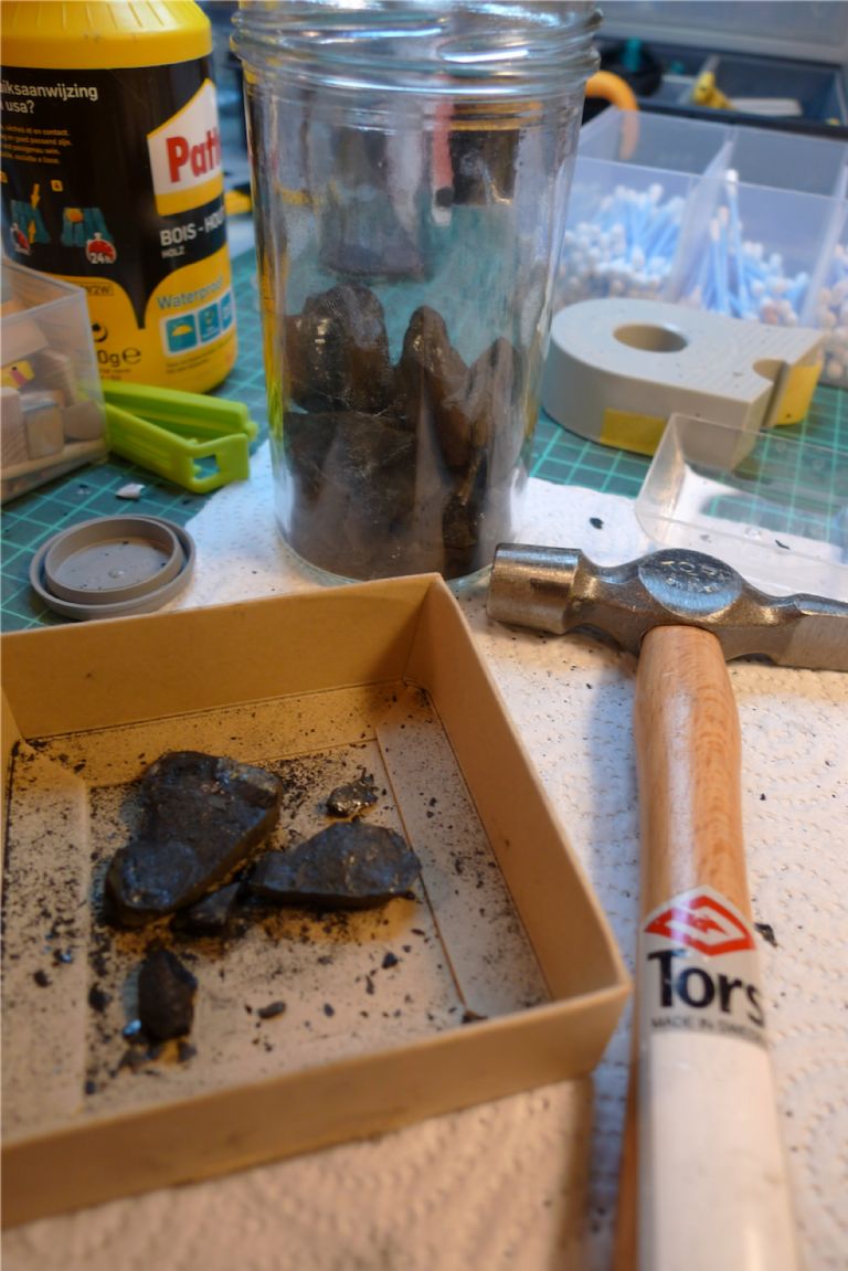
I then applied a hammer to the lumps of coal in order to break them down into suitable smaller pieces …
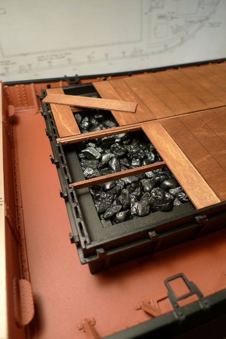
… painted the gravel in black, metallic black and gun metal grey and glued it it place with thick CA glue, while the hatch cover boards were stained light oak and given several coats of satin varnish.
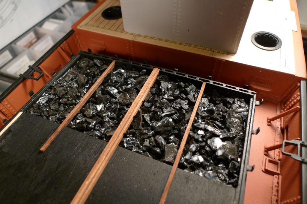
A top layer of real coal was then added and secured with generous amounts of watered-down PVA glue (some white splotches can still be seen in the photo below, which of course turned completely invisible once they were fully dried) and the strongback and side beams were glued in place.
To be continued,
/Mattias
25 November 2014 at 08:32 #53817Banjoman
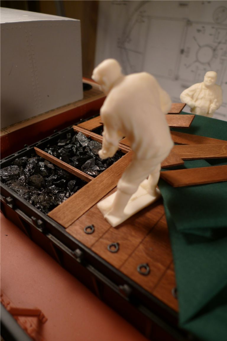
Participant@banjomanAs one of the crew members that came with the kit holds a suitable position, I decided to show him busy pinching some coal from the main cargo to top up the ship's own stores; from what I've read about Puffers, this "fringe benefit" approach to the cargo apparently was not that uncommon. I've even seen references to such ships with a secret hatch in the hold aft bulkhead through which the cargo could be gotten at straight from the boiler room …
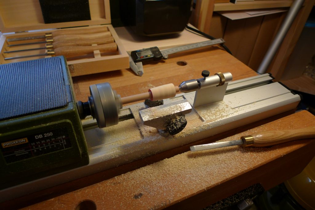
… although for the small-scale pilfering that I had in mind here, I thought a bucket would be more appropriate, and so I decided to try to make one. I first glued an old wooden sewing thread reel to a short length of dowel, set this up in the micro lathe and turned the reel to the right size and shape to serve as a former for a bucket.
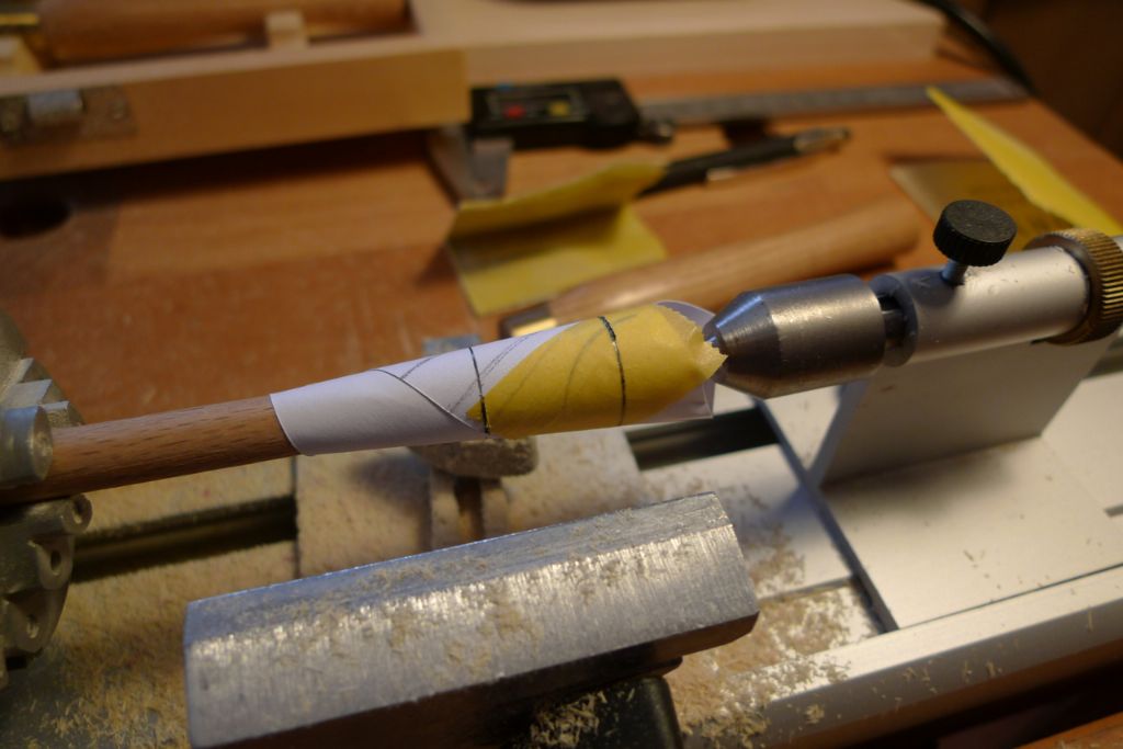
I then put some paper around this former and held a pencil up to the suitable top and bottom marks of the bucket while the lathe was turning. I then removed the paper and carefully cut out the paper along the pencil lines, which when the paper was laid flat became curved and thus gave me the necessary shape of the bucket blank.
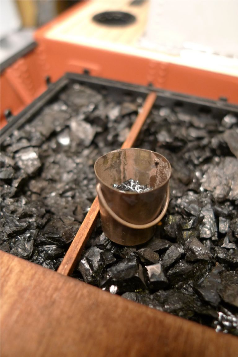
The blank shape was transferred to some brass shim, cut out, drilled for the handles, tarnished with Blacken-it and then glued into a bucket shape on the wooden former. A handle was easilly made from some thin brass wire, also blackened, and the finished bucket measures about 17 mm diameter at the top by some 19 mm high.
To be continued,
/Mattias
Edited By Banjoman on 25/11/2014 08:33:01
Edited By Banjoman on 25/11/2014 08:33:42
-
AuthorPosts
- Please log in to reply to this topic. Registering is free and easy using the links on the menu at the top of this page.
Code of conduct | Forum Help/FAQs
Latest Replies
Home › Forums › Building Kits › Topics
-
- Topic
- Voices
- Posts
- Last Post
-
-
Aeronaut Mahogany Sheet issue
Started by:
floatmeboat2025 in: Beginners
- 4
- 9
-
2 hours, 11 minutes ago
 Colin Bishop
-
TID steam tug 42″ – PN Thomas drawing enlarged
1
2
Started by:
 Ray Wood 3
in: Scratch build
- 8
- 35
-
5 hours, 1 minute ago
 Richard Simpson
-
Lead Zinc boat parts Clean up, and Type of Glue to attach them
Started by:
bruce dixon in: Building Kits
- 3
- 5
-
17 hours, 6 minutes ago
bruce dixon
-
Vic Smeed’s Silver Mist
1
2
…
33
34
Started by:
Bob Abell 2 in: Scratch build
- 5
- 833
-
17 hours, 29 minutes ago
 Ray Wood 3
-
Antique model lifeboat
Started by:
douglarse in: Gallery
- 3
- 8
-
1 day, 2 hours ago
 Richard Simpson
-
Antique lifeboat in auction
Started by:
douglarse in: Buy/Sell or Trade
- 1
- 1
-
1 day, 14 hours ago
douglarse
-
Melton & District Model Club 60th Anniversary Model Show
Started by:
Michael Campbell 2 in: Shows and Events
- 1
- 1
-
2 days, 21 hours ago
Michael Campbell 2
-
Fairey Huntsman 28
1
2
…
7
8
Started by:
 Chris Fellows
in: Build Blogs
- 2
- 197
-
3 days, 20 hours ago
 Colin Bishop
-
Building a hull.
Started by:
 mick east
in: Scratch build
- 7
- 16
-
5 days, 4 hours ago
 mick east
-
Fairey Faun
1
2
3
Started by:
 Chris Fellows
in: Build Blogs
- 7
- 60
-
5 days, 21 hours ago
 Ray Wood 3
-
superglue allergy
Started by:
 Alasdair Allan
in: All things floating
- 5
- 12
-
6 days, 21 hours ago
Tim Cooper
-
Model Yacht Racing – The future ??
Started by:
 Ray Wood 3
in: Sailing Models
- 4
- 4
-
1 week ago
 Richard Simpson
-
Vic Smeed’s Legacy
Started by:
 Colin Bishop
in: All things floating
- 6
- 15
-
1 week ago
 Colin Bishop
-
Eezebilt RAF Fire Boat
Started by:
Tim Cooper in: Build Blogs
- 4
- 9
-
1 week ago
 Colin Bishop
-
Feathered Friends
Started by:
 Chris Fellows
in: Soapbox
- 3
- 9
-
1 week, 1 day ago
 Richard Simpson
-
4D Modelshop
Started by:
Keith Long in: Scratch build
- 6
- 9
-
1 week, 2 days ago
 Colin Bishop
-
Fairey Huntsman 31
1
2
…
5
6
Started by:
 Chris Fellows
in: Build Blogs
- 14
- 139
-
1 week, 3 days ago
 Chris Fellows
-
John Cobb’s Crusader
1
2
…
7
8
Started by:
 Paul T
in: Scratch build
- 1
- 192
-
1 week, 4 days ago
 John W E
-
Complex Automata
Started by:
 Colin Bishop
in: Soapbox
- 1
- 1
-
1 week, 6 days ago
 Colin Bishop
-
RAF Fireboat ID
Started by:
 Dave Reed
in: Collectors’ corner
- 8
- 24
-
2 weeks ago
Tim Cooper
-
Lady of Skye (puffer)
1
2
Started by:
 mick east
in: Build Blogs
- 9
- 43
-
2 weeks, 1 day ago
 Richard Simpson
-
Todays Boating
1
2
…
210
211
Started by:
 ashley needham
in: All things floating
- 84
- 5,252
-
2 weeks, 3 days ago
 Colin Bishop
-
Sea Rover Restoration
Started by:
harry smith 1 in: Collectors’ corner
- 4
- 10
-
2 weeks, 3 days ago
 Richard Simpson
-
WORKSHOP LIGHTING
Started by:
 John W E
in: All things floating
- 9
- 18
-
2 weeks, 4 days ago
 Colin Bishop
-
Mayhem Website Down
Started by:
 Colin Bishop
in: All things floating
- 4
- 10
-
3 weeks, 1 day ago
 Colin Bishop
-
Aeronaut Mahogany Sheet issue
-
Latest Issue
Newsletter Sign-up
Latest Replies
- Aeronaut Mahogany Sheet issue
- TID steam tug 42″ – PN Thomas drawing enlarged
- Lead Zinc boat parts Clean up, and Type of Glue to attach them
- Vic Smeed’s Silver Mist
- Antique model lifeboat
- Antique lifeboat in auction
- Melton & District Model Club 60th Anniversary Model Show
- Fairey Huntsman 28
- Building a hull.
- Fairey Faun


