Tin Plate Clyde Puffer

Advert

Tin Plate Clyde Puffer

Home Forums Scratch build Tin Plate Clyde Puffer

  • This topic has 222 replies, 13 voices, and was last updated 1 week, 3 days ago by James Hill 5.
Viewing 25 posts - 1 through 25 (of 223 total)
  • Author
    Posts
  • #105774
    Len Morris 2
    Participant
      @lenmorris2

      Hi Everybody,

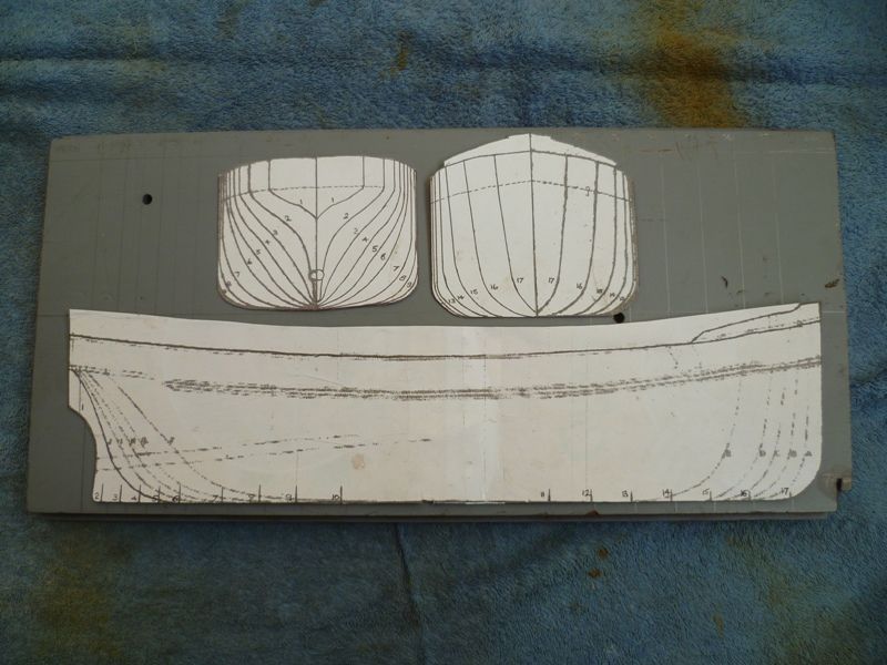
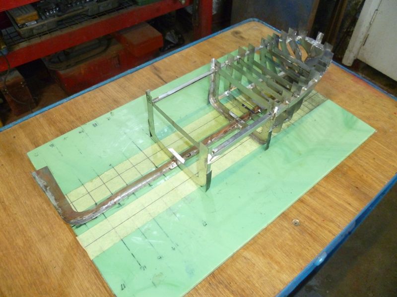
      For a long time I've been considering a steam boat with a tin plate hull. The Clyde Puffer seamed ideal with a good beam for a short length. The hull on the stocks is 18.25 inches long and 5 inches wide. The hull lines were found on the web and enlarged on my printer (several times) to give a workable kitchen table size. They were glued to card to give the starting point.

      p1050075 (1).jpg

      This model was not going to be made from folded sheet, nor was it going to be laid up on a wooden former. I have done both in the past. Sheet is fine for simple forms and hard chine hulls. Wooden formers are good but it's a bit like making the hull twice. This hull is being built ship yard fashion by laying up the keel first.

      p1050077 (1).jpg

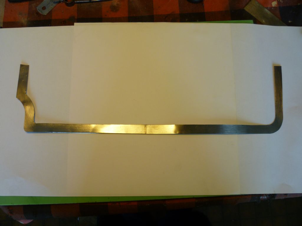
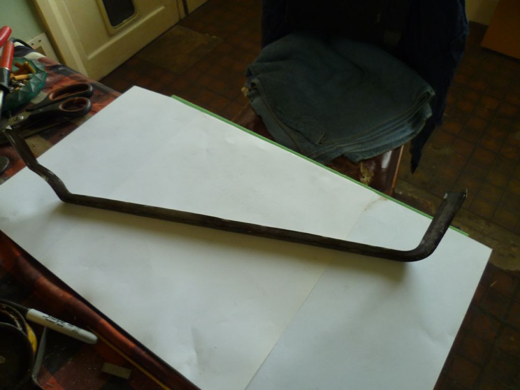
      The picture shows the spine of the keel as a simple piece of flat tin. There is a lap joint in the middle as I didn't have a piece of sheet large enough. The next step was to get it straight and rigid by making it into a 'T' section.

      p1050087 (1).jpg

      Advert
      #7245
      Len Morris 2
      Participant
        @lenmorris2

        Small steam boat made from tin plate.

        #105775
        Len Morris 2
        Participant
          @lenmorris2

          And now to continue! Couldn't get below the last picture to continue typing.

          It shows the keel soldered up as a T section and free standing on the layout board. The next step was to cut the bulk heads.p1050092 (1).jpg

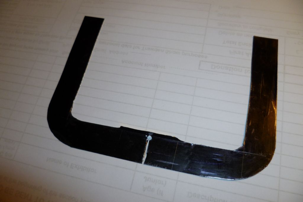
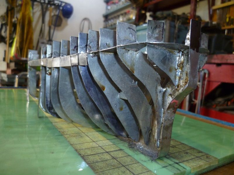
          The picture shows one of the mid sections. It slot allows it to slide over the keel and the small flange in the middle stops it falling in half until soldered in position. The result so far is the stern erected.

          p1050102.jpg

          Of note in the picture are the temporary shoring strips and my work table which is just a large ceramic tile that's very flat. The keel was stuck to this with contact adhesive to stop it slipping during assembly. Here's a better view of the stern.

          p1050099.jpg

          I was tackled first because it was obviously going to be the most challenging. It was nice to feel the whole structure becoming very stiff as the work progressed. The job now is to fit the front frames and the propeller shaft. Hope to get back soon.

          Best Regards,

          Len

          #105776
          Chris Fellows
          Participant
            @chrisfellows72943

            Interesting Len. Certainly different to our usual builds!

            Chris

            #105777
            neil hp
            Participant
              @neilhp

              Len, for anyone not used to soldering such large areas, could you please explain how you have soldered all of these peaces together withour others close to the heat from falling apart.

              What soldering iron or heat sourse do you use?.

              what temperatures do you solder at ?

              what solder you use?,

              and what flux do you use?

              and where do you find a supply of virgin tin plate?

              All of these questions when answered would be of great help to others wishing to follow a similar build project.

              thank you.

              #105778
              James Hill 5
              Participant
                @jameshill5

                Hi Len,

                This is going to be an interesting build to follow, It`s going back to the days when a lot of models were built this way and the skills have been somewhat lost.

                Looking good so far,

                Jim.

                #105779
                Len Morris 2
                Participant
                  @lenmorris2

                  Hi Neil,

                  There's nothing special about the kit I use and no black art about stopping it fall apart when soldering bits close together.

                  None of my material – tin plate – is 'virgin'. It's just old tin cans that are cut up. Gallon cans are good because they provide large areas of ten thou plate. Smaller cans tend to be thinner and are good for 5 to 8 thou material. Some beer cans are steel and give 3 thou material. It's all a matter of the application. The sheet bits are flattened by bending and using an old rolling pin. External paint is removed with paint stripper if necessary but often I leave it in place if it's not seen or going to be soldered. Food tins used to be a good source until they started corrugating the sides. Virgin plate can be found on the web but it's a needless expense.

                  The flux I use is the standard grease like compound I use for domestic plumbing. The current tin is 'Telux', but 'Fluxite' is just the same. A tin will last years. I apply it with a small paint brush along the joint line.

                  The solder is a bobbin of 'AutoSol' 1.5mm wire. It's not cored with flux and is the standard 60/40 composition of lead and tin. Again, a large bobbin will last years. I've never tried any of the newer 'lead' free solders so can't comment.

                  Most of the soldering is done with a standard 'Weller' 40w iron. For larger thicker areas I use an old 'Henley Solon' 100w iron. I found the Weller tips burnt out relatively quickly and replacements hard to find or quite expensive (they are coated with a plated finish). I now make my own from a piece of 1/4 inch copper bar. They work just as well and can be easily shaped for the tip profile needed. Normally that's just a chisel end. None of the irons are temperature controlled. When solder will melt easily on the tip they are hot enough and are turned off after the job to stop oxidation.

                  Where the set up is delicate and touching with an iron is likely to disturb the pieces, I use a small chef's butane torch or a standard plumbers gas torch. All the bits are shown below.
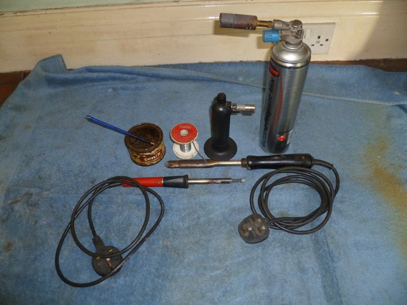
                  p1050103.jpg

                  The neighbouring parts will not fall apart if the golden rules of soldering are followed. The parts should be very clean along the joint line (fine emery paper or scotch bright). The joint line should be well fluxed and close fitting. The iron should be up to temperature and well tinned. Feed solder can be added from the roll (on to the tip, not the part) or cut into small strips and laid along the joint line. If the latter is done touch the solder with the iron not the part. Heat is transferred to the part through the molten solder far quicker than hard contact between the iron and the part. Done well the solder will flash quickly into the joint long before any neighbouring joints even become warm.

                  Hope all this helps. It's simply my experience and might not be the best advice.

                  Best Regards,

                  Len

                  #105780
                  neil hp
                  Participant
                    @neilhp

                    has helped greatly Len, and much helpfull information to take in.

                    i used to soft solder small parts but could never get decent results, but your info is very helpful. cheers.

                    #105782
                    Richard Simpson
                    Participant
                      @richardsimpson88330

                      That's quite a structure, and certainly a very interesting process to watch. Thanks for taking the time to share.

                      #105841
                      Len Morris 2
                      Participant
                        @lenmorris2

                        Hi Everybody,

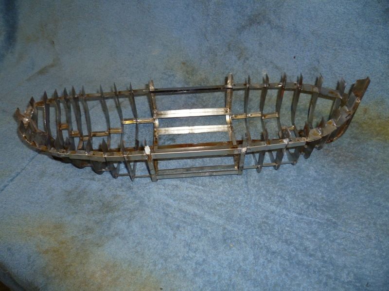
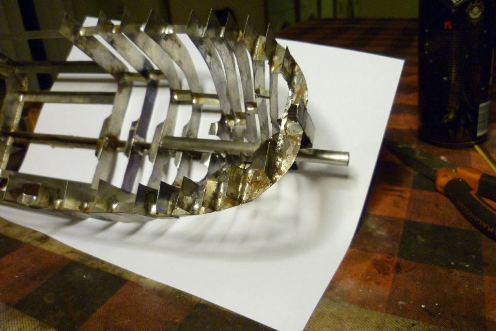
                        The frame is now finished and almost ready for plating. Here it is released from the construction plate with most of the temporary shoring removed.

                        p1050131.jpg

                        #105842
                        Len Morris 2
                        Participant
                          @lenmorris2

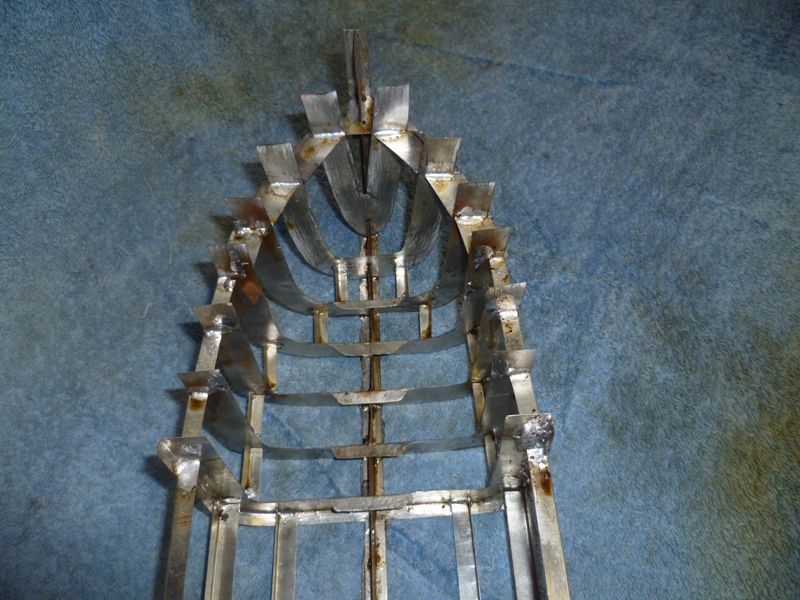
                          And here's a view of the the front frames, the last to be added.

                          p1050132.jpg

                          #105843
                          Len Morris 2
                          Participant
                            @lenmorris2

                            The next step is the prop shaft but I need to find one first. I want it short and parallel with the keel meaning the inside end will be below the water level and hence the shaft needs to be sealed.

                            I have the scars on my back from my model submarines using grease, packing, O rings etc and for my more expensive models used to buy the German Raboesch water proof shafts. They used to be relatively inexpensive and are brilliant for performance but a recent search showed them to be anywhere between 30 and 40 pounds which is not on for a model costing so far 50p. I have found a source for very small lip seals so will probably end up making one.

                            Anyway, all for now,

                            Len.

                            #105844
                            ashley needham
                            Participant
                              @ashleyneedham69188

                              Len. Its not a tiny model. A standard propshaft with nylon washers either end adjusted for absolute minimum play is as watertight as you need. Even if you get a tablespoon or so of water on board after a few hours sailing…what does it matter???

                              A lot of people seem to go to extraordinary efforts to waterproof propshafts, and if I had a lathe I would simply make some extra long nylon bearings for a shaft and that would be that with a smear of waterproof grease.

                              Ashley

                              #105845
                              Len Morris 2
                              Participant
                                @lenmorris2

                                Hi Ashley,

                                Totally agree, particularly for a surface boat but for some perfidious reason I've had shafts that act like water pumps into a hull. I think it's all to do with the black art of hydrodynamics, shaft speed etc.

                                The boat is going to be steam powered and I don't think I'll have a lot of power to start with, so I would like absolute minimum friction which long bearings and grease tend not to give. I do have a lathe and knocking up a 'Raboesch' copy would be quite easy but I'm trying to keep things simple.

                                Thanks for your comments which are well received and food for thought.

                                Len

                                #105847
                                James Hill 5
                                Participant
                                  @jameshill5

                                  So interesting seeing what I would call old style model making, especially when you consider what it`s being made from.

                                  Your progress is much quicker than my wooden effort. Watching with interest.

                                  Jim.

                                  #105850
                                  Len Morris 2
                                  Participant
                                    @lenmorris2

                                    Hi Jim,

                                    I've been following your build as well. It looks excellent and I suspect it will be much better than mine when its finished. Looks like the ponds are going to be full of puffers next year.

                                    I also have the problem of dopes on my boat. In my case it's me!

                                    Len

                                    #105859
                                    ashley needham
                                    Participant
                                      @ashleyneedham69188

                                      Len. When I said grease, I meant a smear only,mainly for initial running. TheSilicone stuff I am currently using is very un-sticky and would cause no drag. I can’t imagine a long nylon bearing on the outer end would have almost any friction being water lubricated. One drip of ‘light machine oil’ on the inner one before a sailing should be all that’s needed.

                                      Possibly….You-could have a lightly steam pressurised shaft…that would keep out the water, a loose fit bearing at the outer end would keep the pressure down and aid propulsion…and the resulting bubbles would help mask the acoustic signature of your prop against any lurking submarines?

                                      Ashley. (Some Comments not to be taken seriously….)

                                      #105866
                                      Len Morris 2
                                      Participant
                                        @lenmorris2

                                        Hi Ashley,

                                        The 'problem' is that when the shaft is soldered in place and the plating done it would be a little bit difficult to ever get it out again and that's a polite way of putting it!

                                        Decided on a compromise that should keep us both happy. I'm going to fit a shaft tunnel first and the prop shaft will telescope into that. Will allow it to go in and out easily and so I can try no end of variants starting with your own simple ideas.

                                        Not worried about subs as my unusual antenna array should make them wary. However it does need to puff (it's a puffer) and I recon it's about 5 beats a second. Not sure yet how I'm going to get that.

                                        Len

                                        #105909
                                        Len Morris 2
                                        Participant
                                          @lenmorris2

                                          Hi Everybody,

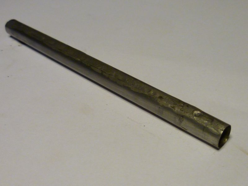
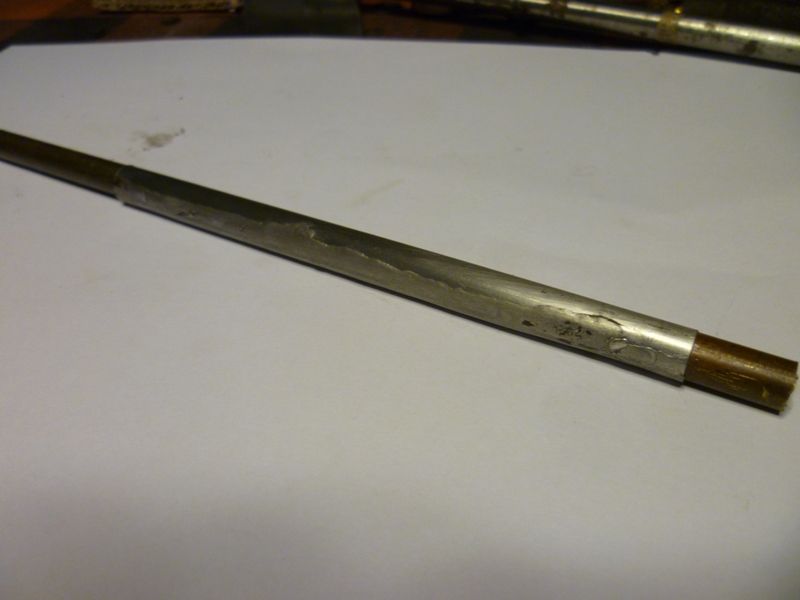
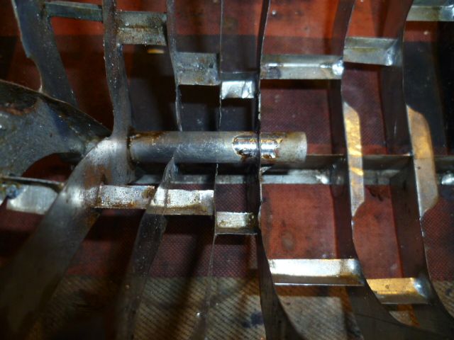
                                          Things are progressing after much thought about fitting the propshaft. The conversation with Ashley helped enormously. The tube soldered into the frame is a propshaft tunnel. There are 3 advantages to this. Being made of tinplate it will solder in very easily. A brass propshaft tube would need a lot more heat and probably need the careful use of a blowlamp. With the tunnel in the frame I can get on with the plating and sort the propshaft out later. And once I have a shaft I'm happy with it will be easy to telescope in and out.

                                          The pics below show the tunnel on its own and slipped over a bit of 8mm diameter (1mm wall) copper tube that will eventually be the shaft. It came out of the scrap bin and I think was the thermostat probe from my old hot water heater.

                                          p1050146.jpgp1050147.jpg

                                          #105959
                                          Len Morris 2
                                          Participant
                                            @lenmorris2

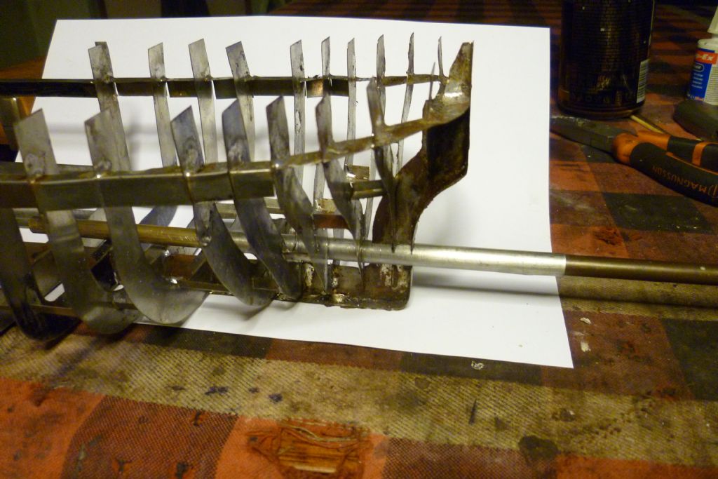
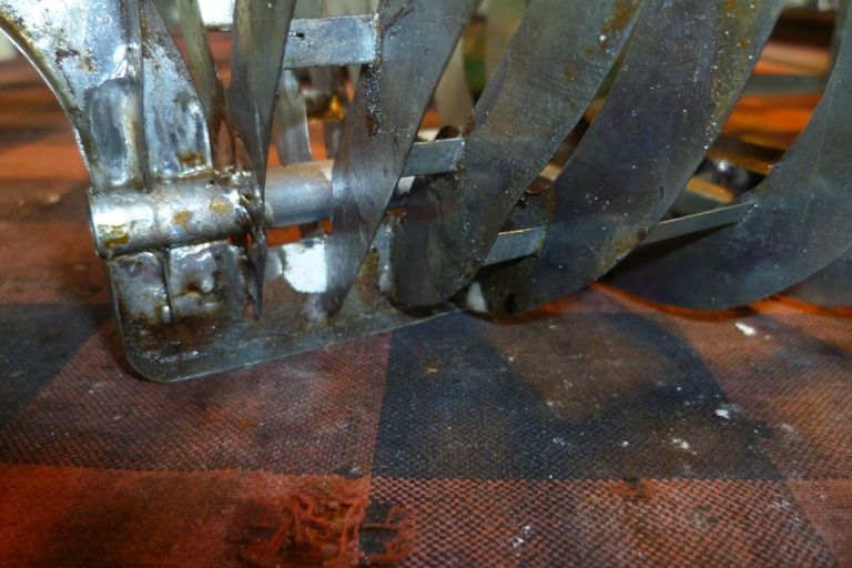
                                            Just a couple of pictures on progress. Here's the shaft tunnel fitted

                                            p1050150.jpg

                                            and here's the propshaft slid inside. Both are over length as I have to think about where the engine is going.

                                            Len

                                            p1050151.jpg

                                            #105975
                                            ashley needham
                                            Participant
                                              @ashleyneedham69188

                                              Len. In awe of your craftsmanship (or is it persistence?).

                                              Great idea the tube, top notch. Very easy to experiment with. Great.

                                              Ashley

                                              #105980
                                              Len Morris 2
                                              Participant
                                                @lenmorris2

                                                Hi Ashley, It's persistence. Working with tin plate is easy and I would argue all day long about it being easier than balsa, fibreglass, etc. However, the problem with 'scratch building' is that you get so far and then realise you've boxed your self into a corner. You 'scratch' your head about how to get out (hence the name for the topic I'm sure!) and it's persistence that will eventually get you out of it. Plus good perceptive comments from nice chaps like yourself.

                                                Len

                                                #106028
                                                Len Morris 2
                                                Participant
                                                  @lenmorris2

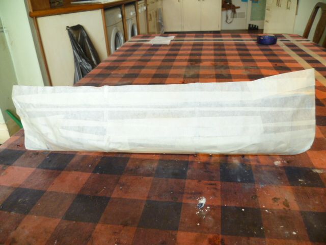
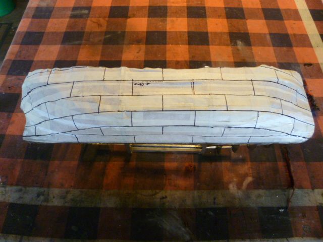
                                                  Things progress. Here are a couple of pictures of the shaft tunnel soldered in place so the propshaft itself can wait for a bit. The last picture shows the frames covered with masking tape. I can now use a felt tip to mark of something like a plating plan and then start making them. I'm not too bothered about following any specific boat. Looking at all the pictures available they all seem a bit different and Len's shipyard was notorious for slapping on any plate that fitted!

                                                  Len.p1050169.jpgp1050170.jpg p1050171.jpg

                                                  #106065
                                                  Len Morris 2
                                                  Participant
                                                    @lenmorris2

                                                    Here's a picture of mi plating plan. It's an artistic interpretation of all the other hulls I've seen so if anybody thinks it it's not right do feel free to comment.

                                                    The number is just my rivet count and I now need to sort out a star wheel to impress the plates (I know people call them pounce wheels but haven't a clue how that's pronounced). The important thing for tinplate is that the indentations will shrink that side of the plate and cause it to bow, just something to be aware of.

                                                    Len

                                                    p1050173.jpg

                                                    #106077
                                                    Len Morris 2
                                                    Participant
                                                      @lenmorris2

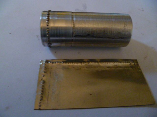
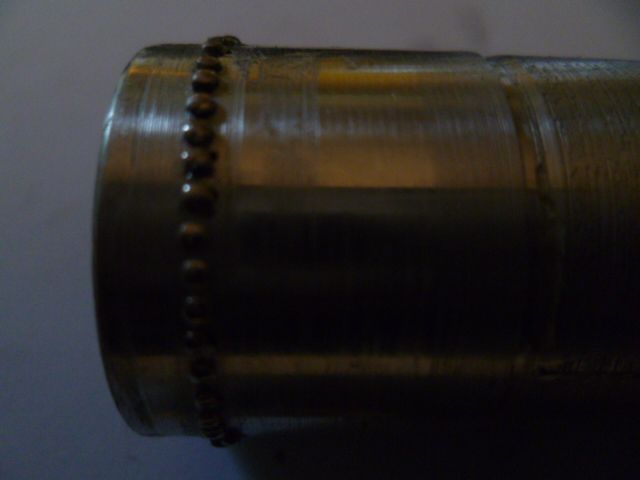
                                                      Here's a picture of my rivet forming tool. It's just a piece of aluminium bar drilled to allow normal pins (pinched out of mi wife's sowing basket) to be pressed in. And also a picture of the results when it's put in the lathe against a hard rubber wheel and a piece of tin plate squeezed between them. Done at 30 rpm as I have some 80 plates to make.

                                                      Len (pictures wrong way round, sorry)p1050174.jpg

                                                      p1050176.jpg p1050175.jpg

                                                    Viewing 25 posts - 1 through 25 (of 223 total)
                                                    • Please log in to reply to this topic. Registering is free and easy using the links on the menu at the top of this page.

                                                    Code of conduct | Forum Help/FAQs

                                                    Advert

                                                    Latest Replies

                                                    Home Forums Scratch build Topics

                                                    Viewing 25 topics - 1 through 25 (of 25 total)
                                                    Viewing 25 topics - 1 through 25 (of 25 total)

                                                    View full reply list.

                                                    Advert