Tin Plate Clyde Puffer

Advert

Tin Plate Clyde Puffer

Home Forums Scratch build Tin Plate Clyde Puffer

  • This topic has 168 replies, 12 voices, and was last updated 1 week, 4 days ago by Len Morris 2.
Viewing 19 posts - 151 through 169 (of 169 total)
  • Author
    Posts
  • #119256
    Len Morris 2
    Participant
      @lenmorris2

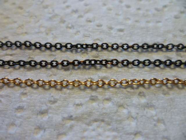
      Just a quick picture of mi rudder chains after getting rid of the brass finish.  The treatment used was ‘Black-it’.  Needs 4 dips in different liquids but only takes about 15 minutes.  It does the job and the nice thing is that it keeps the chains free flowing.

      Len

      P1050427

      Advert
      #119335
      Len Morris 2
      Participant
        @lenmorris2

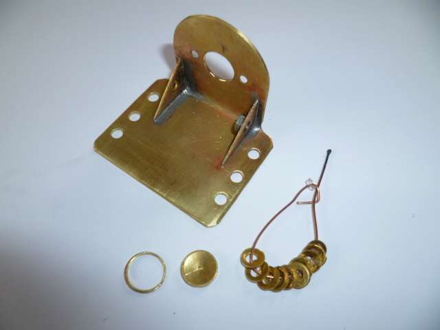
        With mi rudder sorted it’s time to get the motor in.  Here’s some pics of mi mount construction.  It was made from 1mm brass sheet.

        P1050437

        The nut is for an earth connection as the mount will go on rubber.  All the holes were punched.  The bits at the bottom just show how the scrap can be used for making washers etc.  The big one is a 9mm punch through a 10mm blank.

        Here it is sat in the hull.

        P1050440

        Just need to work out how to fix it!

        Len.


        #119338
        James Hill 5
        Participant
          @jameshill5

          Nice work Len. You can’t beat a bit of metalwork now and again…..in your case, all of the time!

          Great stuff…….Jim.

          #119362
          Len Morris 2
          Participant
            @lenmorris2

            Jim, mi decking and wheelhouse are made out of dead trees.

            Len. 🙂

            #119367
            Len Morris 2
            Participant
              @lenmorris2

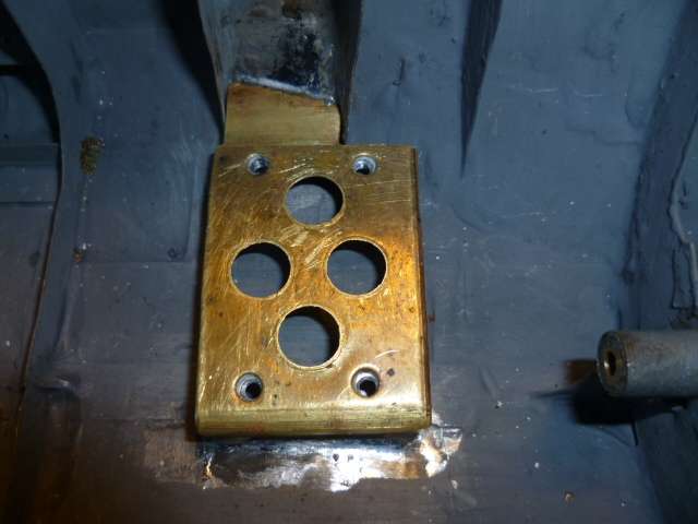
              Just a pic of the base plate for the motor mount soldered into the hull.  Bit of fiddle to get it to fit the hull and be in the right position but got there in the end.

              P1050441

              Len.

              #119381
              Fred Ellis 1
              Participant
                @fredellis1

                Hi Len

                This is looking good, would you be using captive nuts for the fixing of the motor?

                Fred

                #119393
                Len Morris 2
                Participant
                  @lenmorris2

                  Hi Fred,

                  The answer is yes and I should have mentioned it.  If you look closely at mi last pic you can just see the M3 nuts soldered to the underside of the plate.

                  Len

                  #119407
                  Fred Ellis 1
                  Participant
                    @fredellis1

                    Hi Len

                    I did think that you would use captive nuts, seeing as how you had soldered the mounting bracket to the hull, just needed to set my mind at rest.

                    Does the hull act as a sound board when you run the motor? as when I have used a vac formed hull, it acts as a sound board making a lot of noise, so now when I use a vac formed hull I fix the motor down with bath sealant, as that seems to help cut down on the noise.


                    Fred

                    #119418
                    Len Morris 2
                    Participant
                      @lenmorris2

                      Hi Fred,

                      You’re quite right about noise, particularly in a tin hull.  That’s why mi motor has a 2mm rubber sheet between the engine mount and the base plate, rubber washers under the screw heads and the bolts themselves clearance in the engine mount.  In theory the motor’s isolated from the hull mechanically but also electrically.  The nut on the motor mount is for an earth connection to the hull.  Not sure it’s necessary but it might help the suppression capacitors.

                      When I tried an initial run up I was happy with the degree of noise but found that to get the gear alignment set for max speed and minimum amps (only at three volts), I had to leave two of the mounting screws out.  So much for the strive of engineering excellence!  It all came out again and the mount holes were slotted to get the alignment with four screws in place.  Then I realised I hadn’t cut holes in the front plate of the engine mount for the air flow from the fan to exhaust.  All out again and that’s where it lies at the moment.  I’ll post some pics when it’s finally in.

                      Len.

                      #119438
                      Len Morris 2
                      Participant
                        @lenmorris2

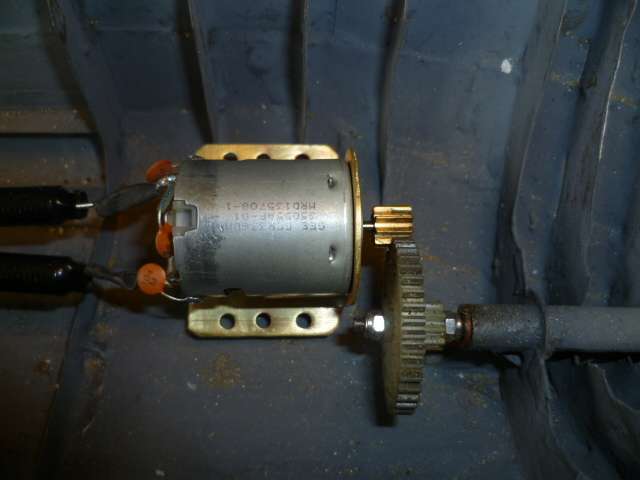
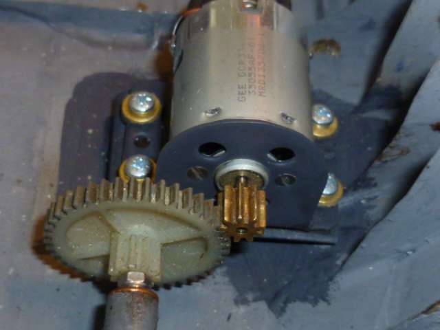
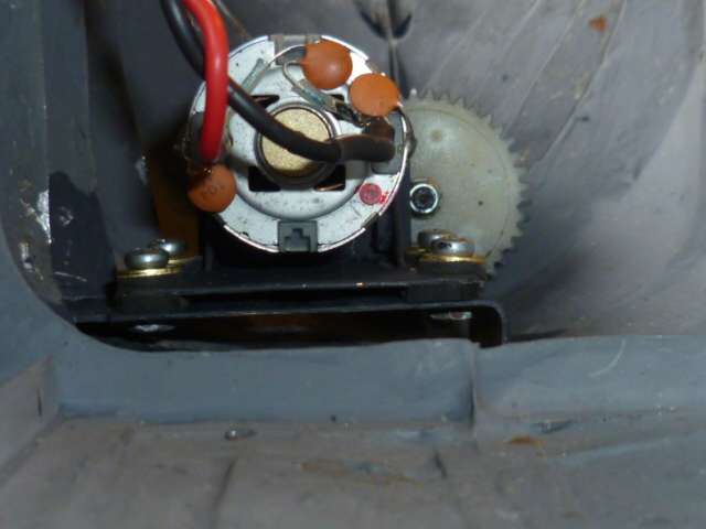
                        Here’s a couple of pictures of mi motor finally fitted.

                        P1050444

                        You can see the air outlet holes in the front plate that I forgot first time round.  Probably not necessary but I suppose it’s good practice.

                        P1050448

                        This just shows the mount sat on it’s rubber sandwich.  The motor noise was quite acceptable and I think that with the decks on, the gears greased and in the water it won’t be an issue.

                        With mi motor and rudder sorted I think it’s now time for another play in the bath to see if she works.

                        Len.


                        #119495
                        Len Morris 2
                        Participant
                          @lenmorris2

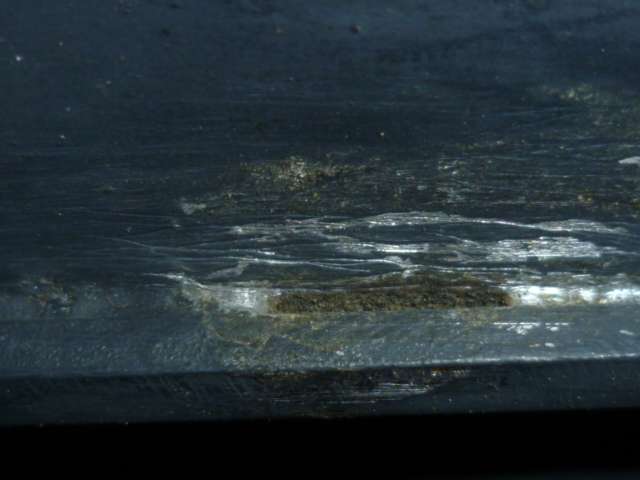
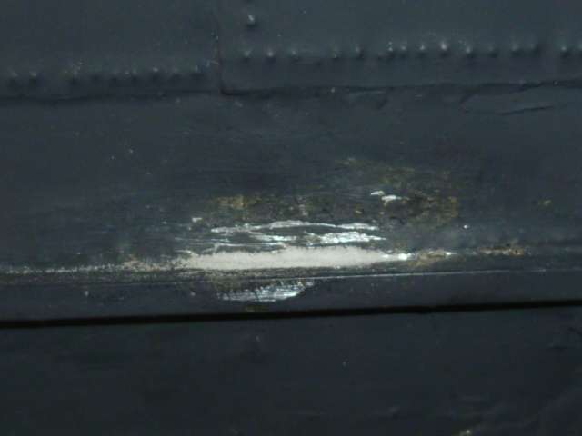
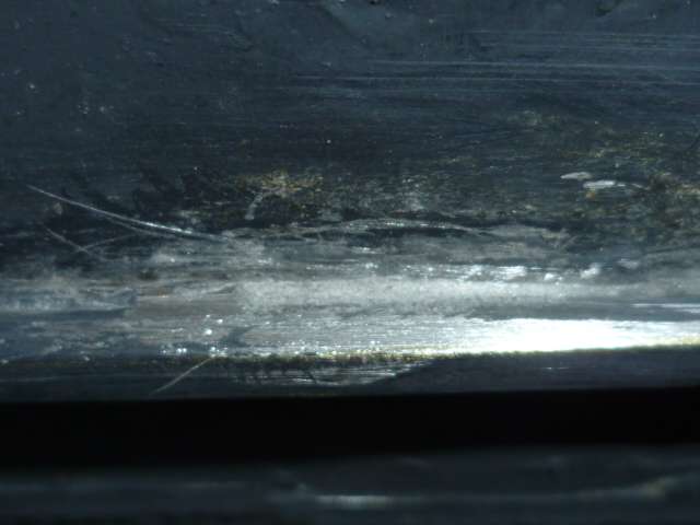
                          She leaked!  Right under the motor baseplate.  Everything had to be taken out again for a close look.  Found the bad seam joint between the keel and the plating about 10mm long.  Lingered too long with the blowlamp fitting the baseplate.  Lesson learned, don’t try tricky jobs late at night after a glass of wine!  Here’s a picture.

                          P1050456

                          Even with all the muck cleaned out of the hole, re-soldering it properly would have needed some serious surgery and jigging to avoid any more collateral damage, so at this stage in the build I just decided to fill it.

                          There are no end of fillers available but I thought I’d try something a bit different using baking soda and super glue.  The main reason was that the powder can be packed down hard into the hole avoiding any trapped air and there’s no rush to get the powder in place.  Here’s a pick of the powder compressed into the hole with the excess brushed off.

                          P1050461

                          And here’s a picture of the repair after a dose of glue.

                          P1050465

                          It set surprising quickly, was nice and hard and proved quite workable with a needle file.  It actually needed very little finishing as it just set where the powder was put.  Not a filler for most boats.  There is an interesting chat about it in ‘All things Floating’.

                          Anyway it fixed mi leak so it’s assembly time again back to the bath.

                          Len.


                          #119501
                          James Hill 5
                          Participant
                            @jameshill5

                            Well done on the repair Len. That’s a method others have tried , as you say, on another posting. In a situation like yours it was an ideal method. Hopefully it’s been sucessfull.

                            My Puffer is in slow mode at the moment as I’m building the engine house and cabin and then planking round both , so things don’t move very quickly. I want to get that area sorted , then move forward to the deck and hatch cover before tackling the mast etc. When there’s enough to show ,I’ll take some pictures.

                            Jim.

                            #119583
                            Len Morris 2
                            Participant
                              @lenmorris2

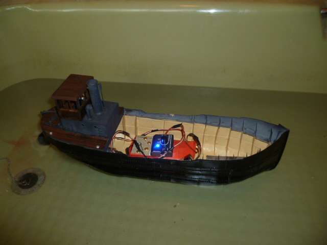
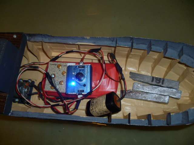
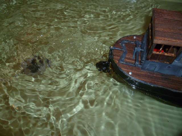
                              She’s now leak free and here’s a pic of her in mi bath.P1050469

                              She’s had a bit of paint for a tidy up and the internal wiring etc is just a lash up to test things.  Here’s a better pic for what it’s worth.

                              P1050470


                              it’s a servo controller for the rudder and 4 U2 dry cells for the motor.  The brass studs just allowed me to pick up the voltage in 1.5 volt increments.  The lead weights were just over half a kilo to get her level and close to the water line.

                              It was a good learning experience.  The rudder worked well enough even with only 45 degrees each way.  She turned through 90 degrees across the width of the bath.  On 1.5 volts she had a pleasant turn of speed (about 5 seconds to get down the length of the bath).  On 6 volts she was like a speed boat with far to much turbulence from the prop.

                              P1050473

                              Hope fully mi Mtroniks speed controller will help or it might be a case of changes to the prop or motor gearing.  The eagle eyed might have also noted the rudder chain missing.  The retaining pin on the rudder arm broke so a bit of a re-design is needed there.  Also the hatch cover, the fore deck and all the other deck fittings need to be made.  Meanwhile, the clocks have gone forward, I can hear mi garden growing and mi lawnmower whispering remember me!

                              Might be a while before mi next post. 🙂

                              Len.

                              #119586
                              James Hill 5
                              Participant
                                @jameshill5

                                The first Puffer in the water and running.

                                Well done Len, it’s progressing well, far quicker than me.

                                I expect a lot of us are like you where the garden is concerned, I know I am. Everything has to be alloted it’s time.

                                Jim.

                                #119592
                                Fred Ellis 1
                                Participant
                                  @fredellis1

                                  Good for you Len the first on the water,

                                  I have just received my new battery from Howes Models, so back to the build.

                                  Fred

                                  #119596
                                  Fred Ellis 1
                                  Participant
                                    @fredellis1

                                    Hi Len

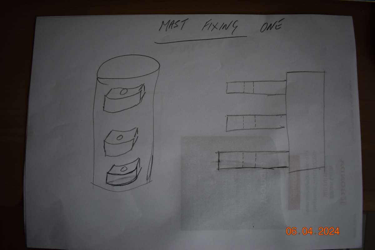
                                    First I am no good at drawing so sorry about this.

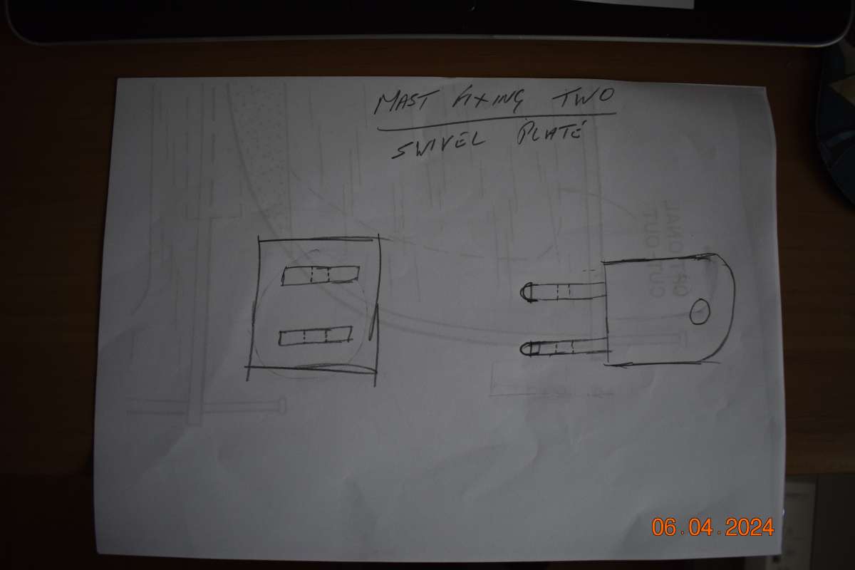
                                    Mast fixing; I used some brass tubing that fitted the mast, to this I soldered some brass plate, before doing this you need to drill a hole in the plates for a fixing pin, the gap between the plates needs to be the same as the plate used in the Swivel plate, the ends of the plates need to be rounded.

                                    Swivel plate; I used some brass square, to this I soldered two plates again a hole has to be drilled in line with the holes in the mast fixing, also a hole needs to be drilled at right angles to the plates in the square part of the swivel plate, so that a fixing pin can fix the boom to the swivel plate, all ends to be rounded.

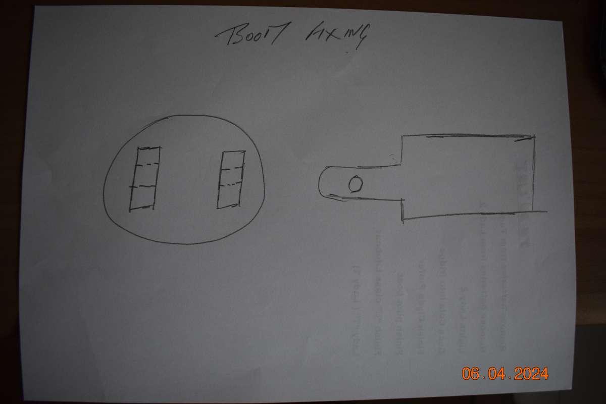
                                    Boom fixing; Again I used brass tubing, I soldered an end cap to one end so that I could fix two plates, these plate need to be able to fix on the outside of the swivel plate, a hole to be drilled for a fixing pin, all ends to be rounded.

                                    The swivel plate goes between the the plates of the mast fixing and fixed by the pin, the swivel plate must be able to move side ways, the boom plates to go on the outside of the square section of the swivel plate and fixed by a pin, this also must allow the boom to move up and down.

                                    I do so hope that this as clear as water.

                                    Fred
                                    _DSC4524_DSC4525_DSC4526

                                    #119600
                                    Ray Wood 3
                                    Participant
                                      @raywood3

                                      Hi Fred,

                                      On a sailing boat we would call that a Gooseneck 🙂 but maybe not on a derrick ?

                                      She coming on well !!

                                      Regards Ray

                                      #119604
                                      Len Morris 2
                                      Participant
                                        @lenmorris2

                                        Hi Chaps,

                                        Very kind comments but I’m not sure paddling about in the bath amounts to a launch!

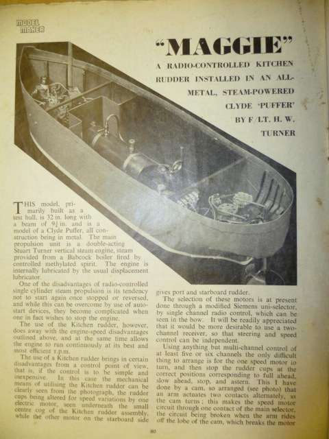
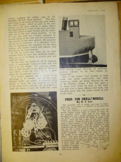
                                        Anyway, found this in mi 1958 copy of Model Maker.

                                        P1050476

                                        P1050477

                                        I just wonder if I read it as a lad and it just stuck in one of my last remaining brain cells.  I also registered on the Model Boat Mayhem site.  It’s very active.  A search for Clyde Puffers came up with no end of entries.  A clever chap on there built an excellent model during the Covid crisis and named his Puffer ‘Loch Doon’.  Just brilliant!

                                        Len. 🙂

                                        #119775
                                        Len Morris 2
                                        Participant
                                          @lenmorris2

                                          Hi All,  I think there is something going on with ‘Latest Replies’.  I check it everyday and there’s not been a lot in the last week.  Then today Fred’s and Ray’s postings suddenly appear from a week ago!

                                          Fred, I think I understand what you intend for your mast and it sounds good to me.  Do post some pics as you make the bits.

                                          Thanks to storm Kathleen and our great British summer I managed to ignore the garden and get a bit more done.

                                          P1050483

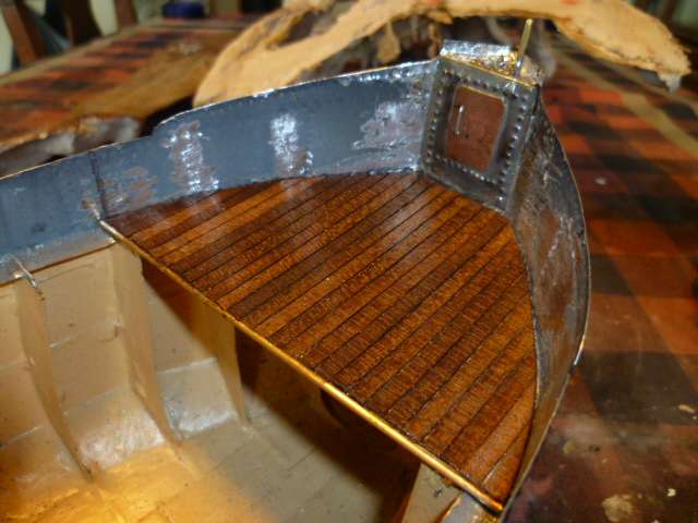
                                          The plate at the prow is soldered to the hull and the vertical pin is for the anchor winch.  There’s also a a small eye that’s just visible for the mast rigging.  The tin foredeck is clad with veneer planking and free at the moment.  It’ll probably end up being screwed down so I can keep the hull clear.

                                          Len


                                        Viewing 19 posts - 151 through 169 (of 169 total)
                                        • Please log in to reply to this topic. Registering is free and easy using the links on the menu at the top of this page.

                                        Code of conduct | Forum Help/FAQs

                                        Advert

                                        Latest Replies

                                        Home Forums Scratch build Topics

                                        Viewing 25 topics - 1 through 25 (of 25 total)
                                        Viewing 25 topics - 1 through 25 (of 25 total)

                                        View full reply list.

                                        Advert