The world's leading magazine for all model boating interests
Galileo – A resurrection
Galileo – A resurrection
Home › Forums › Sailing Models › Galileo – A resurrection
- This topic is empty.
-
AuthorPosts
-
13 January 2019 at 14:19 #80654
Tim Rowe
Participant@timrowe83142Hello Ray
The carbon rudder stock is straight grained ie the fibres run the length of the tube and it is quite thick walled. The rudder trunk is also a carbon tube but is spiral wound and with a thin wall. I am hoping the two will be compatible as they are a close sliding fit. I have a slight concern that the there is any moisture penetration into the fibres, especially in the trunk, it might swell and lock up. I have a couple of offcuts that I can leave in a cup of water to see what happens.
If you are thinking of building a boat, roughly speaking the hull will be a third of the total cost so that 32' Cat would be quite a lot of money.
Tim R
13 January 2019 at 16:02 #80655 Ray Wood 3Participant@raywood3
Hi Tim,
I enjoyed building a couple of wooden boats, but that's when it gets expensive finding somewhere to keep them 😮 this was my 1988 challenge, bought the wreck of this Jaguar 21 lifting keel trailer sailer, after the 87 gale she had been rammed on her mooring on the tidal Medway and sunk! My dad told me it was a waste of time, so the gauntlet was thrown down, needless to say 6 months later we were sailing her again 😀 happy with models these days.
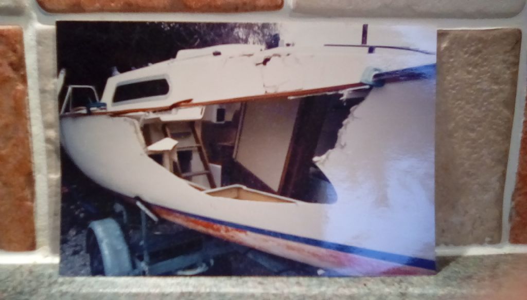
I expect you have surveyed worse?
Regards Ray
A testament to West epoxy resin 😇
Edited By Ray Wood 2 on 13/01/2019 16:17:06
13 January 2019 at 16:50 #80656Tim Rowe
Participant@timrowe83142Hats off to you Ray.
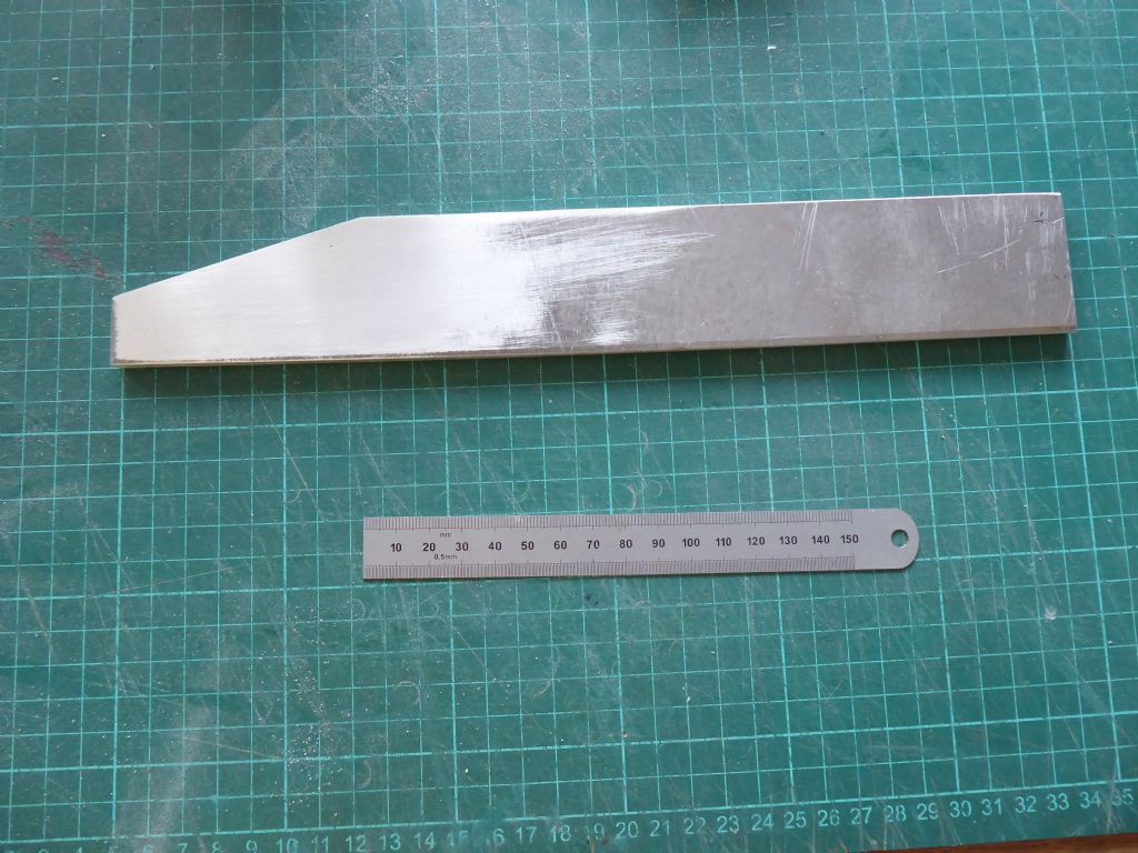
Galileo needs a keel. I had some marine grade aluminium sheet at 6mm thick which seemed to fit the bill. A local engineering company guillotined the blanks for me from a drawing I produced.
Here is the fin keel blank with the top to the left. There was enough material for two more fins for my other projects. The guillotine bent the material a bit so some hefty whacks with a large nylon hammer was needed.
A deep keel is inconvenient when storing and working on the boat so I wanted to make it detachable. On the other hand I wanted it to be very secure when in place and to line up perfectly every time. This is the reason for the taper which fits inside a matching housing. The IOM method was followed in principle.
A taper of 7 degrees (14 degrees included angle) or less is locking taper. This was not what wanted and so the taper was made at 16 degrees included. This means that it will register the keel very accurately but will need a fastening to hold it in place. This is easy to do and I will come back to this later.The aluminum fin is probably right on the lower limits of area given the planned sail area and I don't want to have the keel constantly on the point of stalling. The boat will be mainly sailed in a harbor where relatively speaking, it might be quite rough. A shall probably add a bit on the leading and trailing edges to increase the area and this could also be helpful in establishing a decent aerofoil section. Otherwise there will be a lot of filing to do

Tim R
13 January 2019 at 18:49 #80657 Colin BishopModerator@colinbishop34627
I had a Jaguar 21 for a while. Sailed well but it was a bad buy with various leaks and delaminations. Fixed it up and sold it as too expensive to park a boat on the South Coast that isn't regularly used.
Colin
13 January 2019 at 19:10 #80658 Ray Wood 3Participant@raywood3
Hi Colin,
The Jaguar was ideal in the Medway when we put the fin keel in the mud, you could nip below and wind it up a bit and get going again, kept it for 3 years & sold it to chap in Essex, went back to dinghy racing a Fireball after that, you can't beat having your bum over the side on a screaming broad reach 😆
Regards Ray
13 January 2019 at 19:42 #80659 Chris FellowsParticipant@chrisfellows72943
To echo Ray, I'm impressed with the taping for the fillets! And I thought I was a bit of a perfectionist! Impressed with the laminated beams as well, actually I'm impressed with all your workmanship and attention to detail. Should look great when it's finished.
Interested to see how the keel progresses; I've been doing some more on the drawings for the Fairey Fisherman 27 but still haven't finally decided on that aspect.
Chris
13 January 2019 at 22:35 #80660Tim Rowe
Participant@timrowe83142The idea behind the keel is to tie the big loads into it so there is provision for the mast step (in this case a compression post as the mast will be deck stepped). There is also the shrouds which support the rig laterally and somewhere there has to be a mount for the sheet winch that can generate considerable force and needs to be firmly anchored.
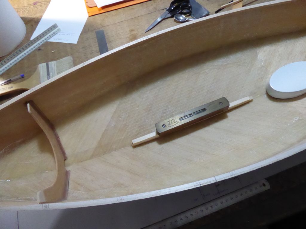
First job was to make a template to conform to the rocker of the hull. I need the top of the keel box to be parallel to the waterline so the hull is back on the building board and levelled up. The template was adjusted until the top was dead level fore and aft and this gives me a datum to work from. The position of the template as penciled into the hull for future location.
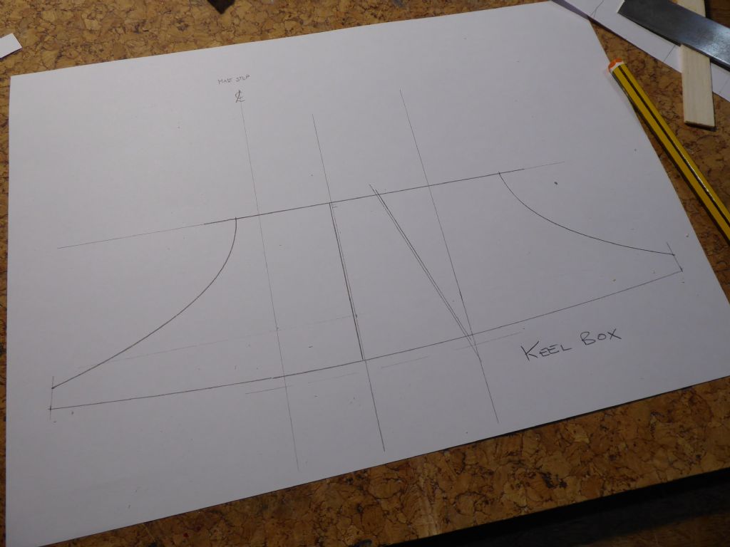
The next stage was to make a drawing. The template was traced around to give the bottom profile and the top of the case drawn a few millimetres above the taper on the fin. This extra distance is important. The case is shown with the bow to the left and the position of the mast step drawn on. The taper was matched to the alloy fin and then it was ready to go.
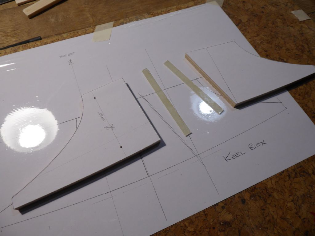
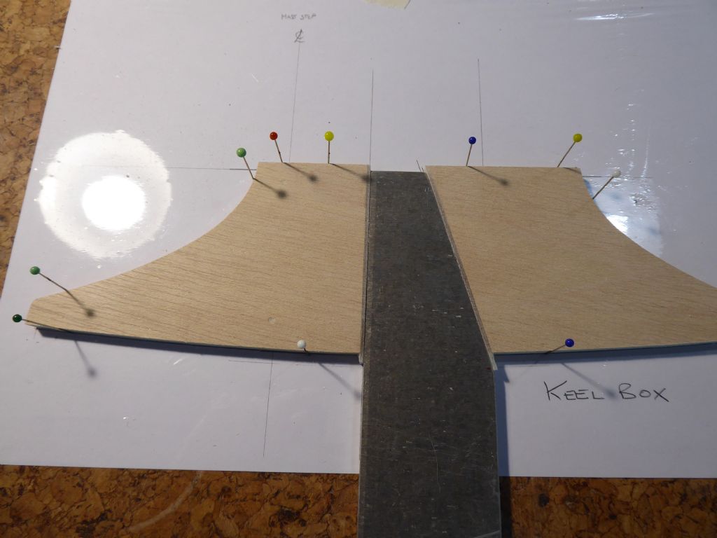
The plan was then copied and the fore and aft section of the cut out and pasted to laminations of 3mm Liteply. A note here is that Liteply often comes warped. If the two pieces are cut so that the bow in the material is opposite and leaves a gap in the middle, the bow cancels out when the two pieces are glued together and clamped flat. This is better than having the bowed pieces touching in the middle and trying to get the edges closed.
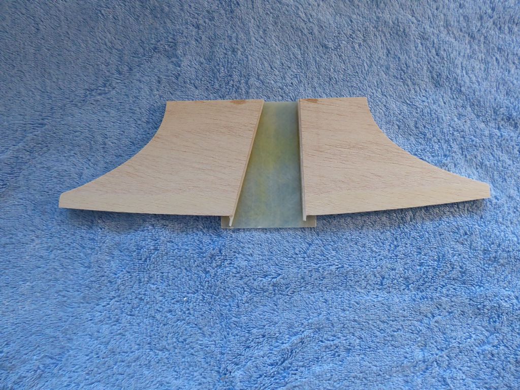
The two thin strip are epoxy laminates. I felt that having a plywood box would not be hard enough and putting the keel on and off would wear it out and if the keel got knocked either when sailing or in storage, the ply would get bruised. Another consideration was then any paint inside to box would soon get worn off and water would soak into the play. The keel box is therefore lined with epoxy.
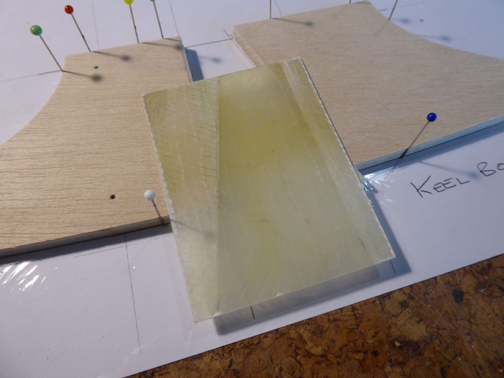
The epoxy laminate material was made by laying up material on a sheet of glass. This gives a flat and smooth surface one side to work from. I used one layer of 45/45 bi-axial at 600 grams per metre squared (gsm) and a top layer of chopped strand mat at 300 gsm. This gave me a nice strong flat sheet of 1.2mm to cut parts from.
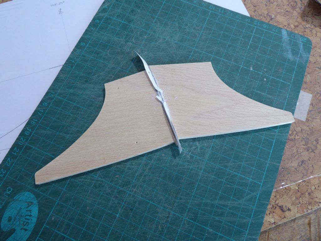
The strips were epoxied to the fore and aft ends of the keel box and here they are simply back to back to hold them in place while the glue sets. The paper was a precaution in case the two pieces stuck together. The paper did its job.
The two pieces of the keel box were relocated on the plate and some more epoxy sheet was cut to form the side of the box. The dull areas are where the sheet was sanded to get a good key for the glue and to protect the non sanded areas masking tape was used.
Continued.
13 January 2019 at 22:51 #80661Tim Rowe
Participant@timrowe83142Keel box continued
This shows the alloy fin in place. It is important that the taper of the fin and the casing are well matched.
Here is the box with one side in place. The ends and the sides project beyond the line of the hull because when the box is fitted I want to extend right through the hull to protect the opening in the hull. Any excess can be trimmed off later.
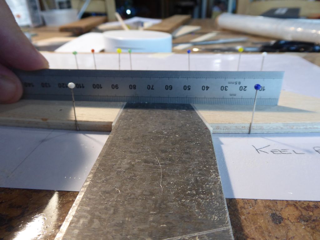
Here I am checking that the box will end up the right width. I hand to sand a fraction off the Liteply core to get the exact width of the alloy. No light showing under the rule so we are ready for the other side.
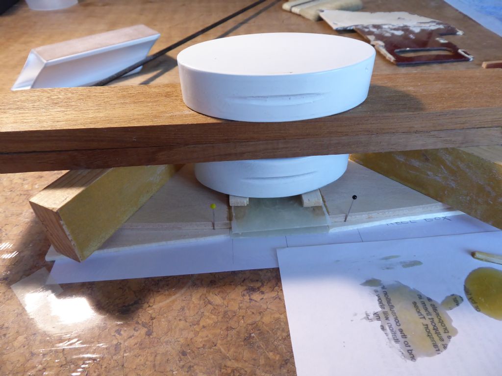
A combination of weights was used for the final assembly. The box was raised off the board with two pieces of balsa slightly thicker than the side piece. This meant the case could sit flat. The bottom weight is bridged across the glue areas as I don't want any weight trying to close the box. The top weigh bridges the whole assembly to make sure it stays perfectly flat.
I always keep the remnants of the mixed epoxy adjacent to the work as this give me an indication when the glue has set sufficiently before handling. Sometimes it is helpful to trim edges when the epoxy is still a little green.
In this case the assembly was left alone for a day to ensure a good cure before removing the weights. This part has to be strong and true.
Tim R
14 January 2019 at 22:41 #80668Tim Rowe
Participant@timrowe83142While waiting for the keel box to thoroughly cure, including two days on the radiator it was time to get on with the rudder trunk. Not working from drawings I had to use the references that were available so back on the building board and leveled up on the waterline in both directions.
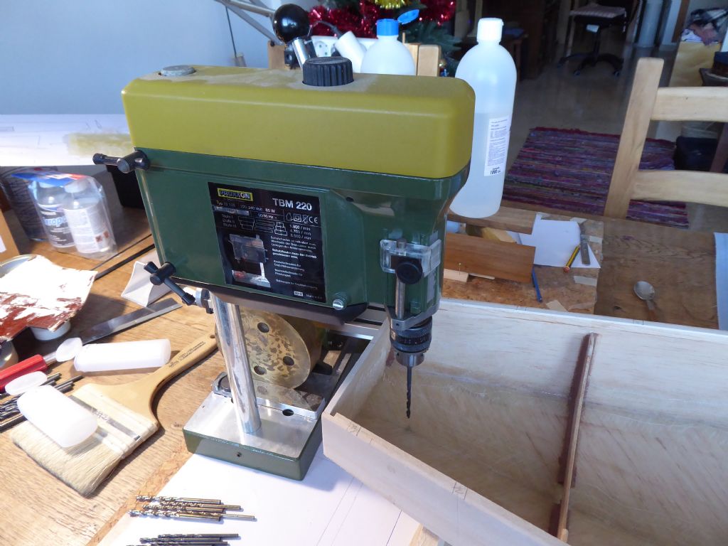
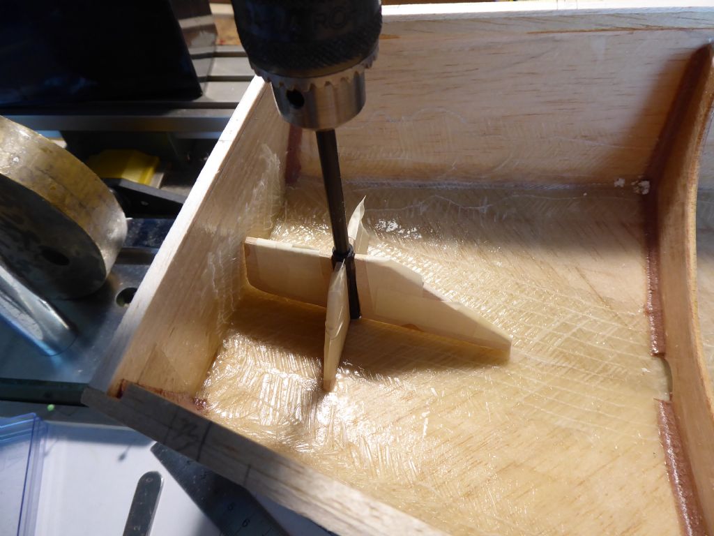
I am a bit of a Proxxon fan and here I am using one of my most used tools. The drilling spindle reaches into the hull and is counterbalanced by some weights on the base. I this way I was able to control the drilling very easily. The hole itself was not too critical as it is only going through 4mm of hull.
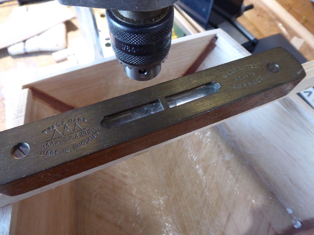
Final check that the hull is perfectly level. I drilled the hole a fraction undersize just in case I had to stretch it to one side or another to get it dead on the external centerline. The was just as well because it was slightly out
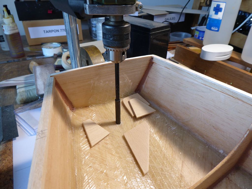
The main reason for using the drill press was this. The rudder trunk was slipped over a spare length of carbon tube the same as the stock and the carbon held in the drill chuck. Doing this made sure that the rudder trunk was truly vertical and restrained while I built up the supports. The Liteply supports are here ready to tack in place with 5 minute epoxy.
Like this. I know, obsession again as the four supports are masked up ready for the fillets to be applied. The side pieces have notches in the lower corners so no water can be trapped.
The trunk is now very well supported by an "open" structure. That is that there are no hidden surfaces that would be difficult to coat or paint.The keel box is now ready so that's the next job as I am getting close to filling the bath to see what weight is needed to bring the model onto the waterline. Looking forward to that very much.
Tim R
16 January 2019 at 17:09 #80685Tim Rowe
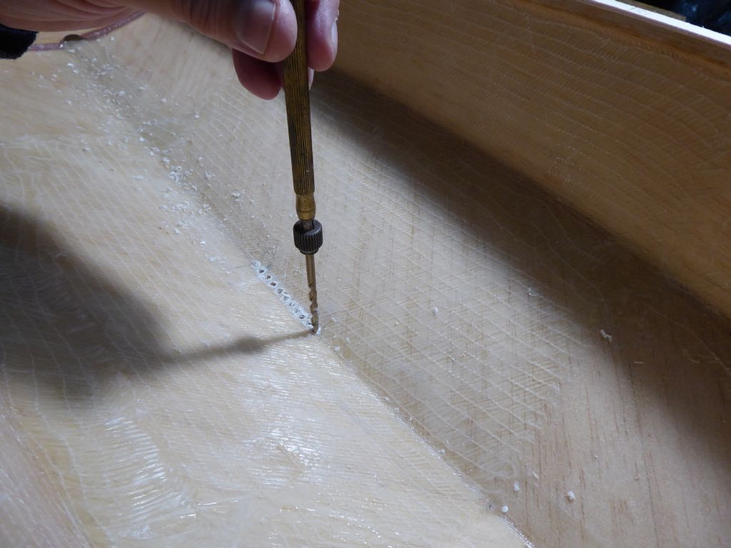
Participant@timrowe83142Back to the keel and the hole needs to be cut in the hull. Before doing any glass work I marked the fore and aft position of the keel inside the hull directly onto the balsa. The epoxy glass lining remains semi-transparent and so the lines remained in view.
This time my pillar drill would not reach so I did a line of chain drilling by hand using a pin vice. The holes took out most of the material and the slot was then opened up with a sanding tip in a Dremel.Chain drilling by hand.
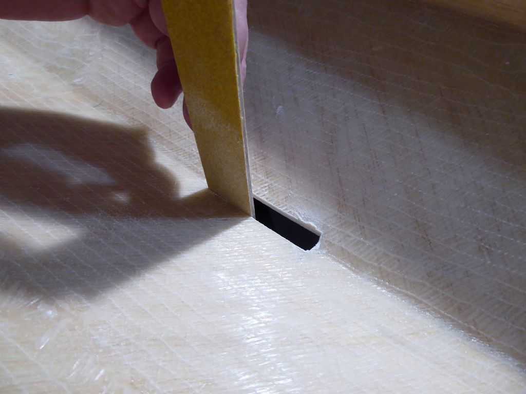
Truing up the slot with a home made sanding board. Some 120 grit paper stuck to a piece of ply with contact adhesive.
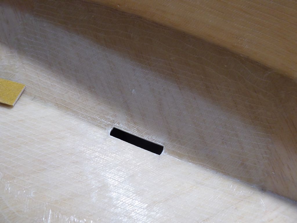
The completed slot about 2mm all around bigger than the keel box. I did not want a tight fit for two reasons. Firstly I wanted some freedom of movement to line the whole assembly along the centerline without using the slot as a register as it is too short to be accurate. Secondly, I wanted to flood the join with epoxy to make sure that the balsa part of the hull gets fully wetted out and protected.
Here the keel box is dropped into position and checked for good alignment.
The gap was taped on the outside to prevent the epoxy running out. As usual the keel box and hull were taped and the fillet applied. In this case I used epoxy bulked up with balsa wood dust. The fibrous nature of the dust makes a stronger fillet than using micro-balloons and this is the only area where it was used.
The keel box is help perfectly upright using a straight piece of 6mm balsa which was a good neat fit in the keel slot. The balsa was pinned to a temporary beam that had the centerline carefully marked on it.The V of the hull gave perfect longitudinal alignment.
The top of the keel box is some way above the waterline upright and when heeled. Even unsupported the keel box was very secure even with bracing but that is coming up.
Tim R
16 January 2019 at 22:01 #80692 Chris FellowsParticipant@chrisfellows72943
When forming the keel box I was expecting to see you cover the epoxy sheet sides with some more timber to provide additional strength. I realise that there is more to do though and guess that the epoxy is there just to stop water ingress and not to take any side load?
Chris
16 January 2019 at 23:42 #80695Tim Rowe
Participant@timrowe83142Hi Chris
The box itself is incredibly strong. Inside the box, the front and back liners are epoxy laminates and bonded to the skins so these are resisting the splitting forces that will occur when the boat is heeled. I will find a photo of the inside of my IOM and it is amazing how fine the internal structures are around the keel and mast.
I am trying to keep the weight of the hull down as mush as possible so I can put more in the bulb. I have now finished the inside of the boat and next time around I will show the bracing and support for the servo tray. The only birch ply I am using in the whole boat is at the attachment for the forestay and the shrouds. Here I need local strength and hardness to take the fastenings. More or less these will be the only fastenings as everything else is glued.
Mainly I think our boats are heavily over engineered but time will tell and I have hat ready for eating!
Tim R
17 January 2019 at 11:56 #80698Tim Rowe
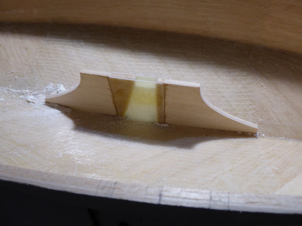
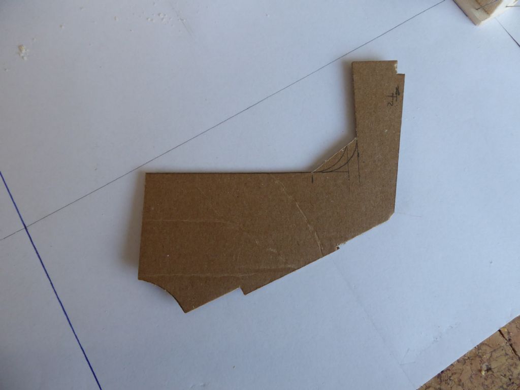
Participant@timrowe83142Now to finish the keel. The Liteply parts of the keelbox mainly are there to make up the width of the alloy fin and also to provide a support for the mast step and servo tray. It was always the intention to provide bracing and so firstly I made some thin card templates.
Three were needed each side to make the supporting webs.
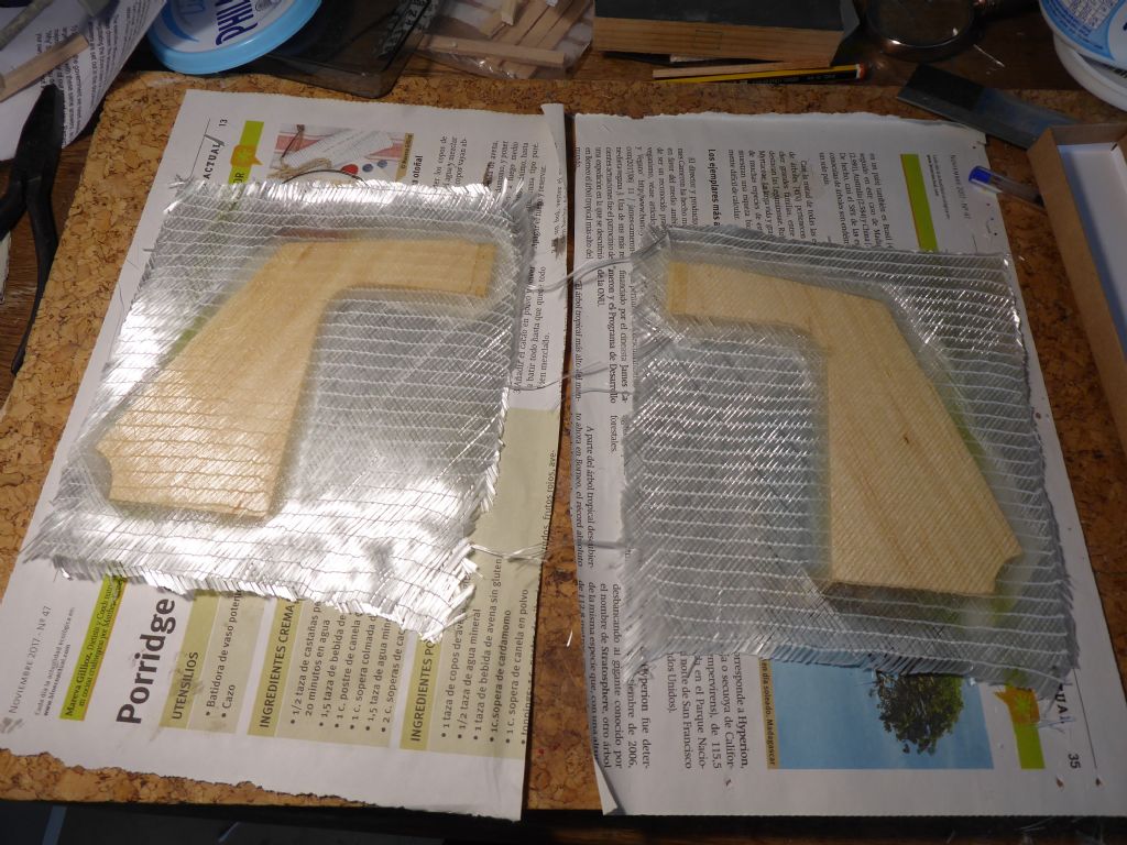
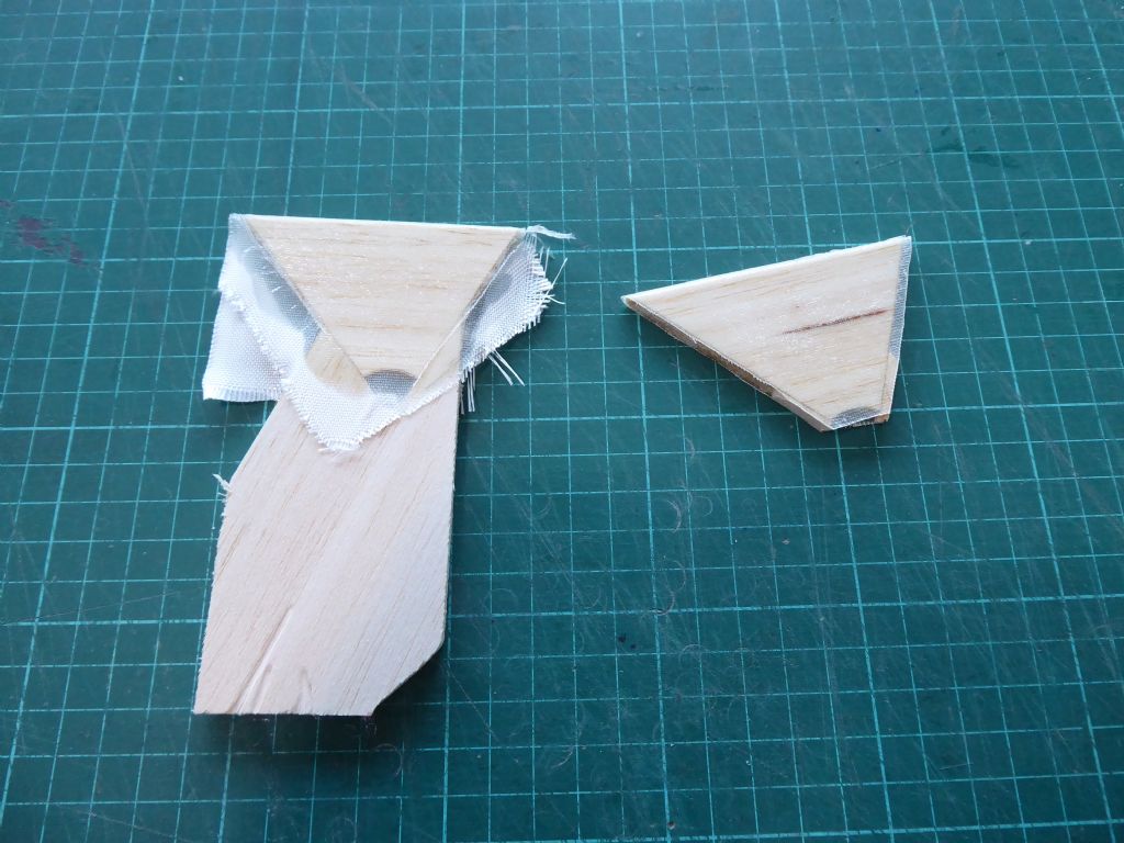
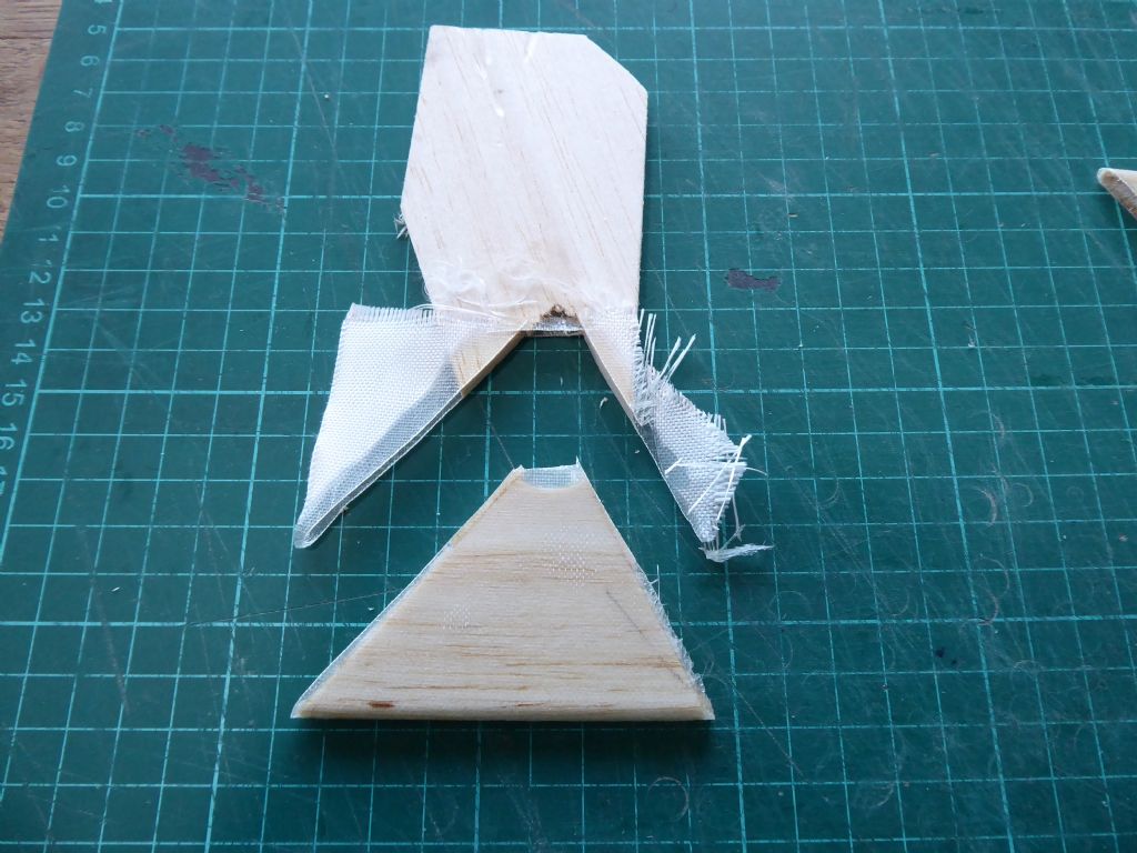
The webs were made from 5mm lightweight balsa and skinned with glass and epoxy. These webs have more work to do and are therefore covered with the medium heavy bi-axial cloth. The others were skinned with a light woven cloth.
The smallest webs were skinned on both side at the same time to get a good wrap around the radius. To do this they were spot glued to a balsa handle and then separated with a sharp knife before the epoxy had fully set.
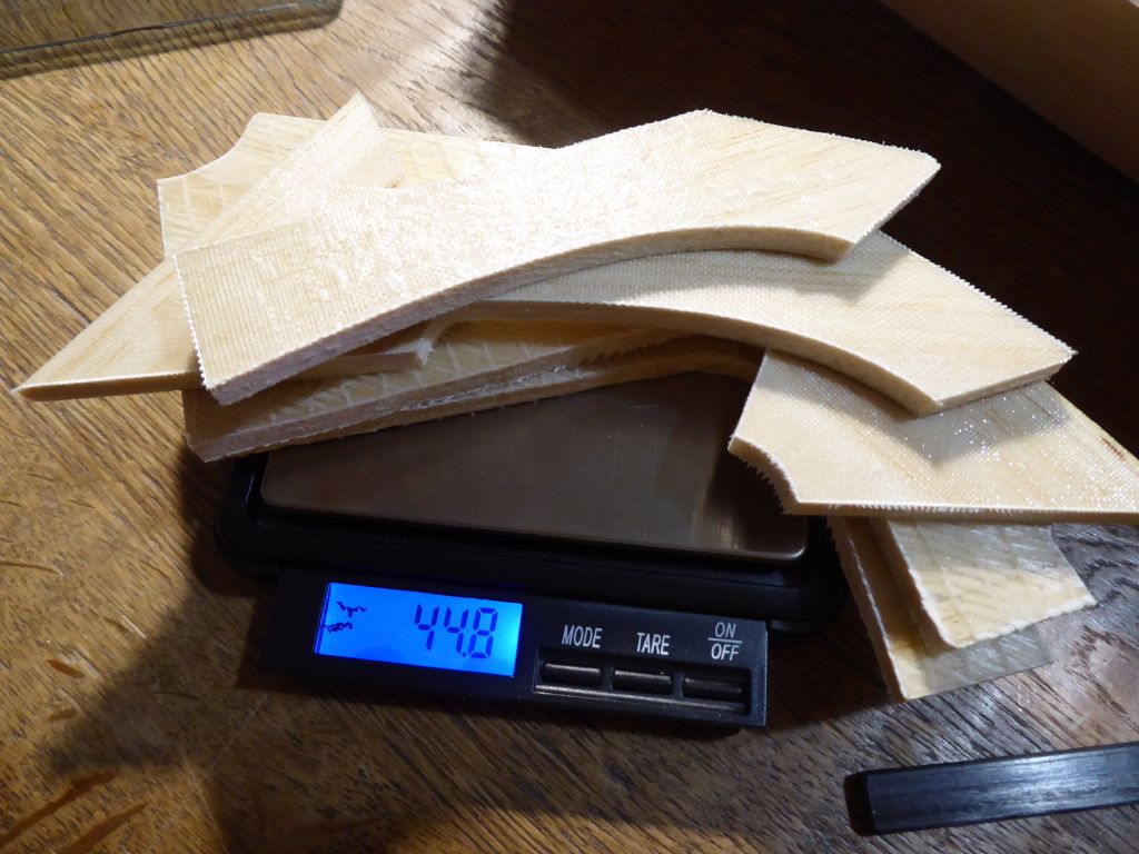
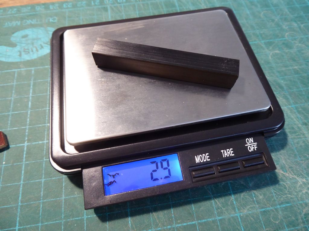
All six pieces were weighed as a matter of interest.
And only came to a skinny 45 grams. I solid ply they would have been nearer 150 g so that is an extra 100 g to go in the heel,
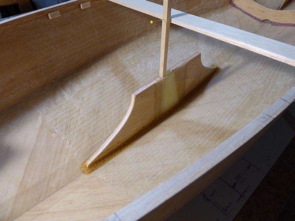
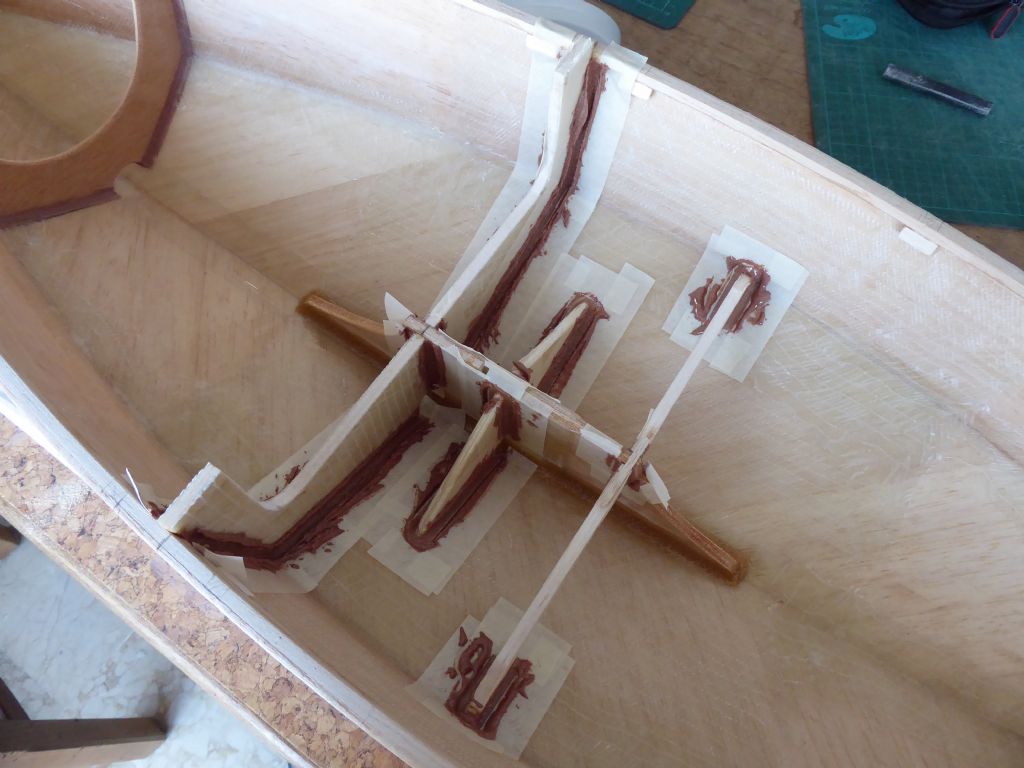
Some more taping and the pieces are now glued into the boat using the fillet technique,
It is worth doing the taping. It means you can be quick and messy when applying the fillets and you don't end up with more than you need again helping me with my weight equation.
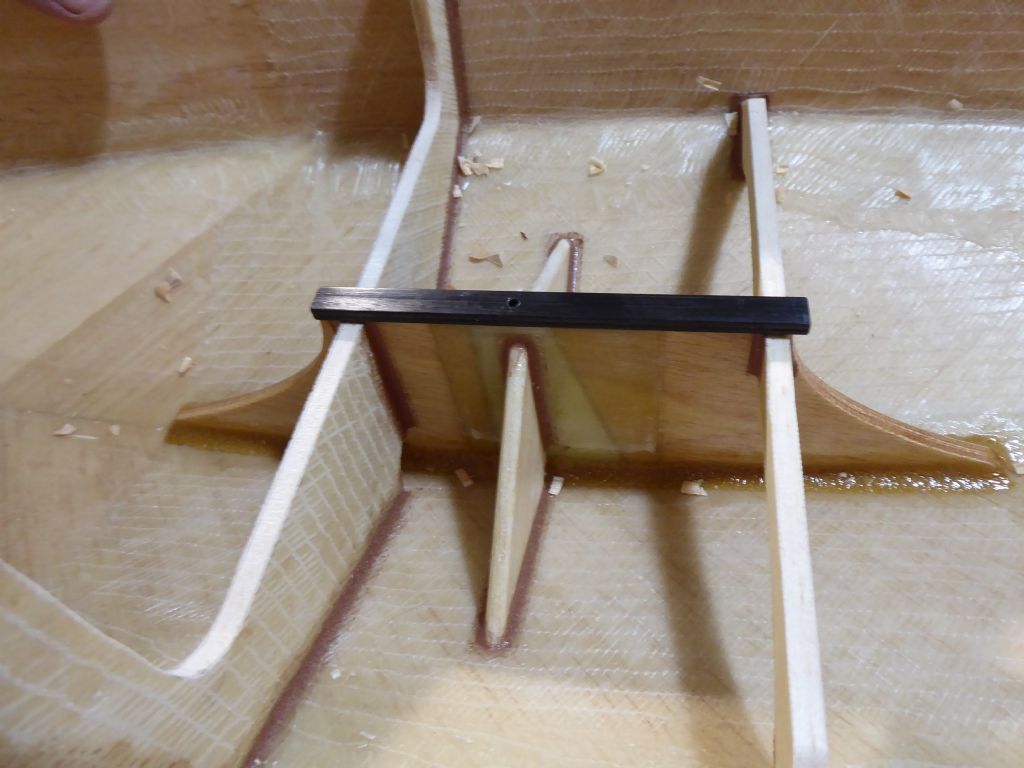
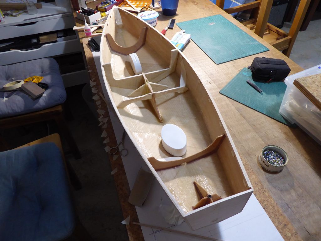
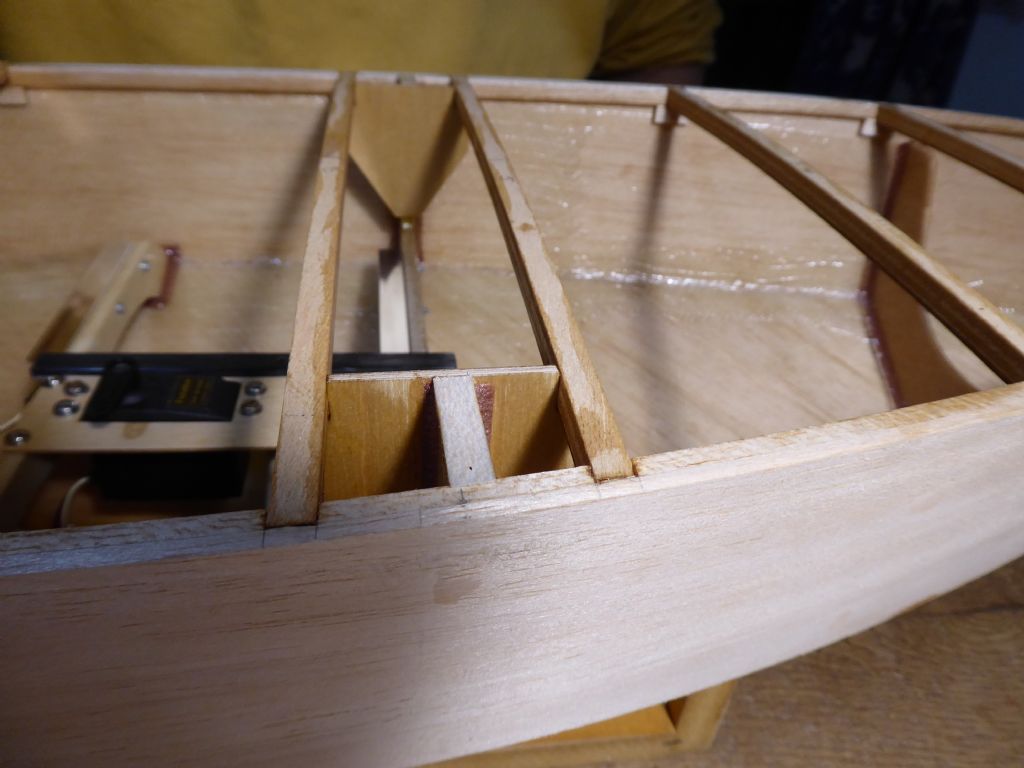
Here is the finished structure. The frame to the left extends up the topsides because this is where the chainplates will be attached. The centre web is a belts and braces web supporting the epoxy section of the keel box. The web on the right gives some lateral support to the keel box but is mainly there to provide a level mounting surface for the servo tray.
The black piece along the top is a carbon fibre strip. This ties the three webs together and provides a hard base for the mast compression post. It also forms the top of the keel box effectively sealing it. I am quite certain the centre webs are redundant but seeing as the only weigh a few grams I am content to have them there.
The inside of the boat will stay finished with clear epoxy as this will help me see any future problems. The glass with turn white if there is any over stressing or fracturing.
This is another view showing the general arrangement. Here they were being tested for fit before tacking in place with rapid epoxy.
Tim R
17 January 2019 at 13:42 #80699 Chris FellowsParticipant@chrisfellows72943
My boats are certainly over-engineered but I'm not worried as they are powered and I like them to have a bit of weight to them. The Fisherman is a motor sailer but the sails on the full sized craft only provided mediocre performance, so again will not be an issue. Obviously a yacht is a different matter and it is beneficial to keep the weight as low as possible.
I will continue to watch with interest how you deal with the keel to mast interface.
Chris
21 January 2019 at 10:30 #80765Tim Rowe
Participant@timrowe83142Chris
I like the Fairey Fisherman. I think it is a very pleasing design although I agree not a high performer sailing wise. Enough though to turn the motor off on a run or a reach. I grew up on the Hamble river with the Fairey yard on my doorstep. Looking back it is amazing the number of different types of boat they made and the sheer numbers. It was a sad day when the autoclaves got flooded.
Progress slows as the details start to be needed plus there are always other distractions. The hull shape was fixed by the original but all the internal structure and fit-out is completely different.
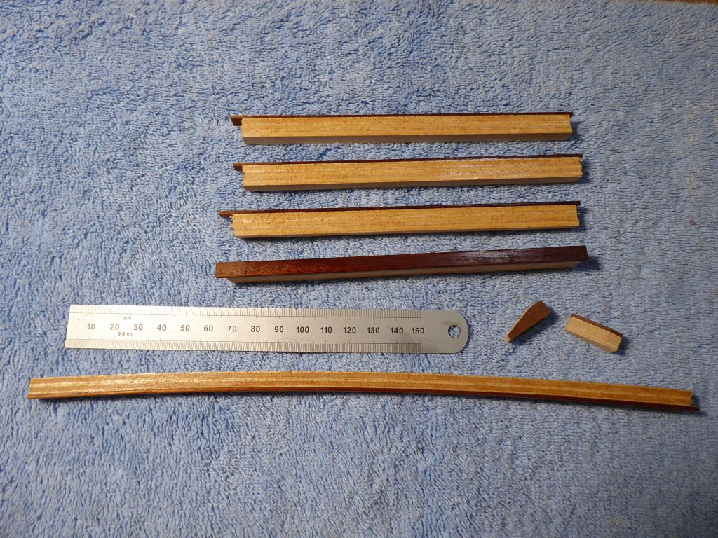
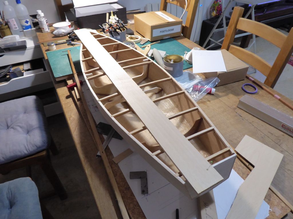
The model is now ready for some deck beams. I showed some previously but now they have their extra laminate of 1mm mahogany. This gives a nice contrast to the rather anemic Liteply and being much harder, stiffens up the beam substantially. The mahogany is on the underside of the beam.
Here is a sample beam and the carlins ready for the hatches. The carlins are deeper than the beams by one extra laminate of Liteply so they can be notched under the deck beams for extra gluing area. The carlins will go in at the last minute before fitting the deck because the width of the hatch will be determined by access to the servos and RC gear. I want the hatch to be as narrow as I can get away with.
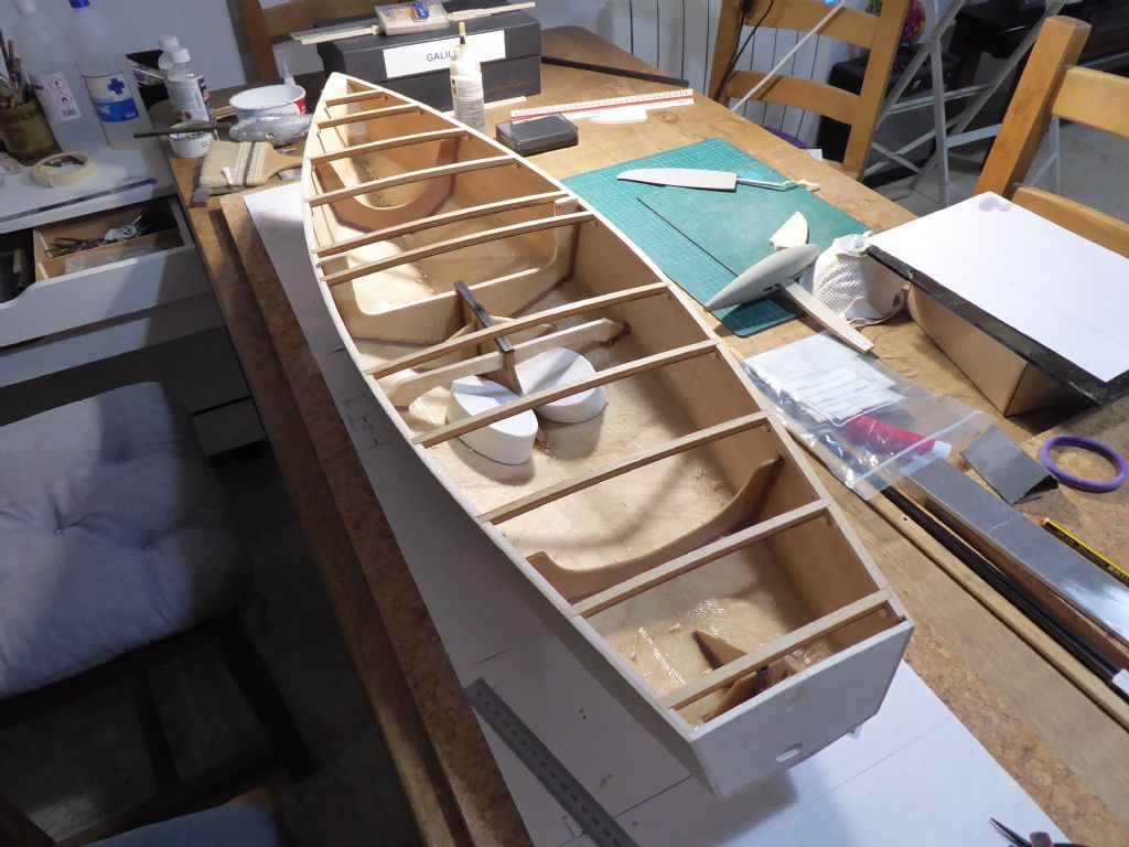
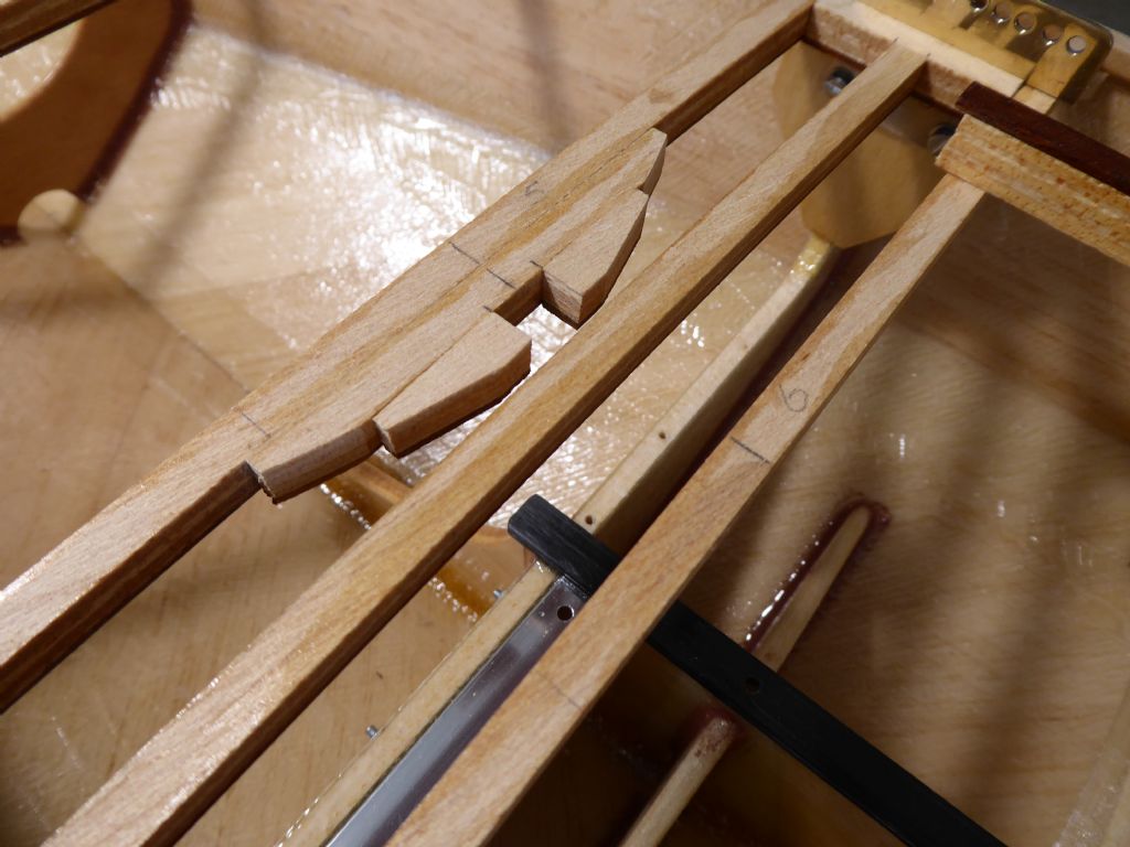
Here the deck beams have been dry fitted. The ends of the beam are notched into the inwhale at an angle. This means that the side sheeting is not cut at all and the inwhales only half way through. This is quite important because if too much is cut out, the fair curve can be lost and the topsides becoming facetted.
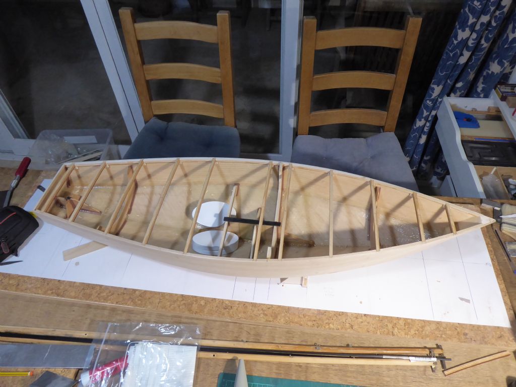
This is the final check for hull symmetry with a straight piece of balsa sheet pinned on the centerline at the bow and transom. The line was marked on the deck beams and then checked with a rule that the distance to each hull side was the same. The maximum variation was a fraction over 2mm and therefore not noticeable in the scheme of things.
With the deck beams glued in place the hull is really quite rigid. The camber of the beams is doing its stuff and they too are good and strong.
The weights are there to stop the hull dancing around while I work on it. They were made by casting lead into sardine tins made from aluminium. The aluminium was then peeled off. I stuck some 3mm MDF to the bottom to stop them marking anything and painted the rest to avoid constantly handling the lead surface. They are really handy so I will make some more when I cast the bulb for the keel.
The model is evolving at each stage and I make little sketches of details and arrangements before doing anything for real. It pays to leave the deck off for as long as possible to keep the internal access open. There will be nothing structural about the deck and as yet I am undecided on how to finish it. It will start with a 2.5mm sheet balsa sub-deck whatever.
Now to the chainplates.
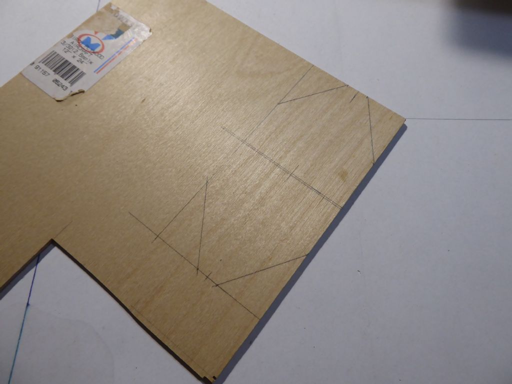
Here the webs are marked out on a piece of 2.5mm ply.
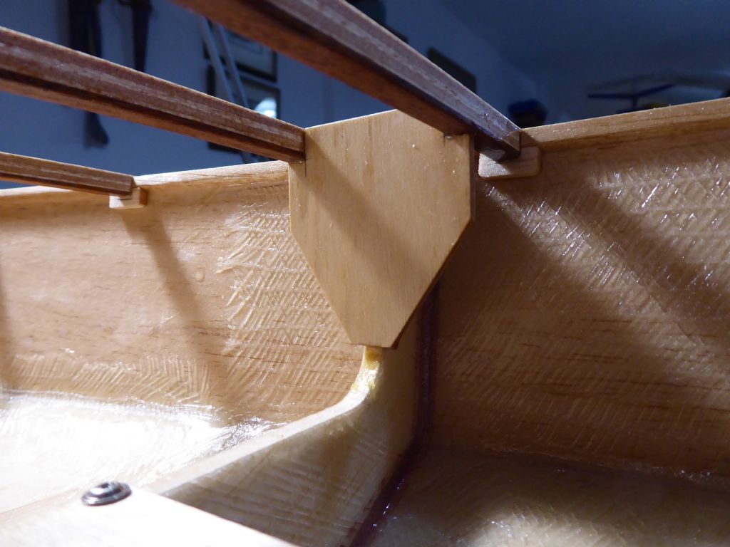
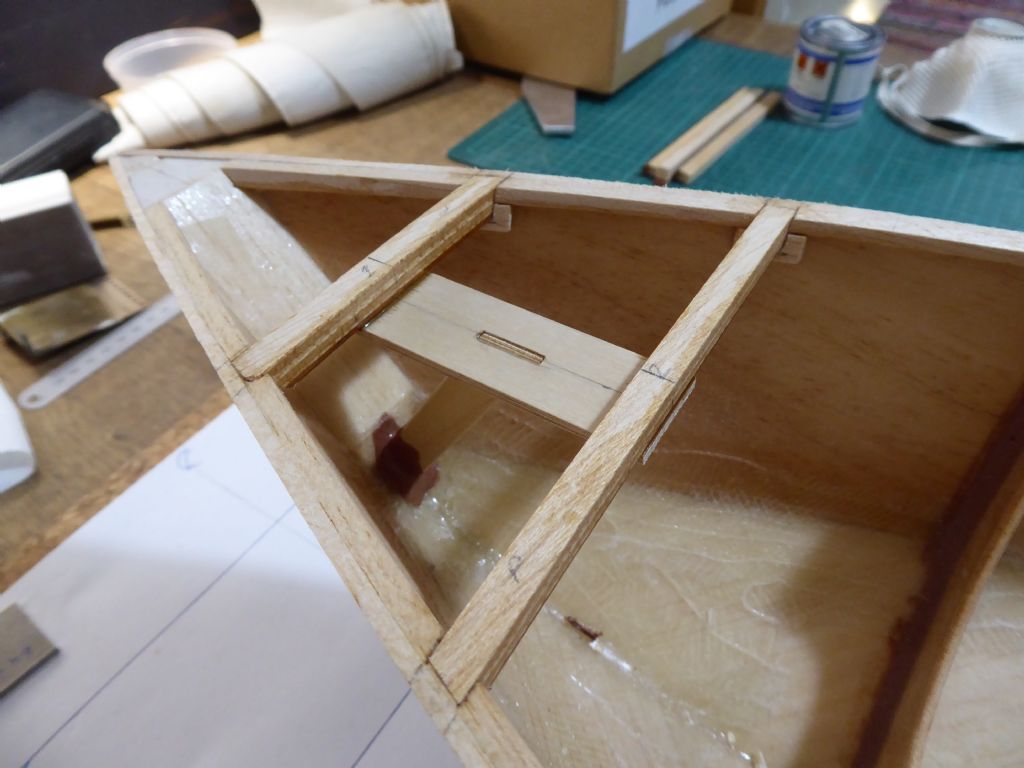
The web is glued to the inner edge of the web frame. This is the frame at the fore end of the keel box and is inline with the mast step.
As per usual, the web is secured with epoxy fillets and notched into the two closely spaced deck beams.
This is the plate for the forestay attachment. The plate is glued to the underside of the two forward deck beams and the plate is tied into the stem with another piece of ply glued and filleted at the lower end and slotted into the deck plate. This means that there are no forces trying to peel the deck off.
The backstay will be attached to a brass tang bolted through the transom. This will be fitted externally and will therefore be added after painting. The backstay is the lightest loaded part of the rig. The forestay is the next heavily loaded and the shrouds the most because of the relatively narrow angle.
With the deck beams in place it is starting to look much more yacht-like.
Tim R
21 January 2019 at 11:25 #80768Tim Rowe
Participant@timrowe83142I am trying to re-use as many of the original fittings as possible.
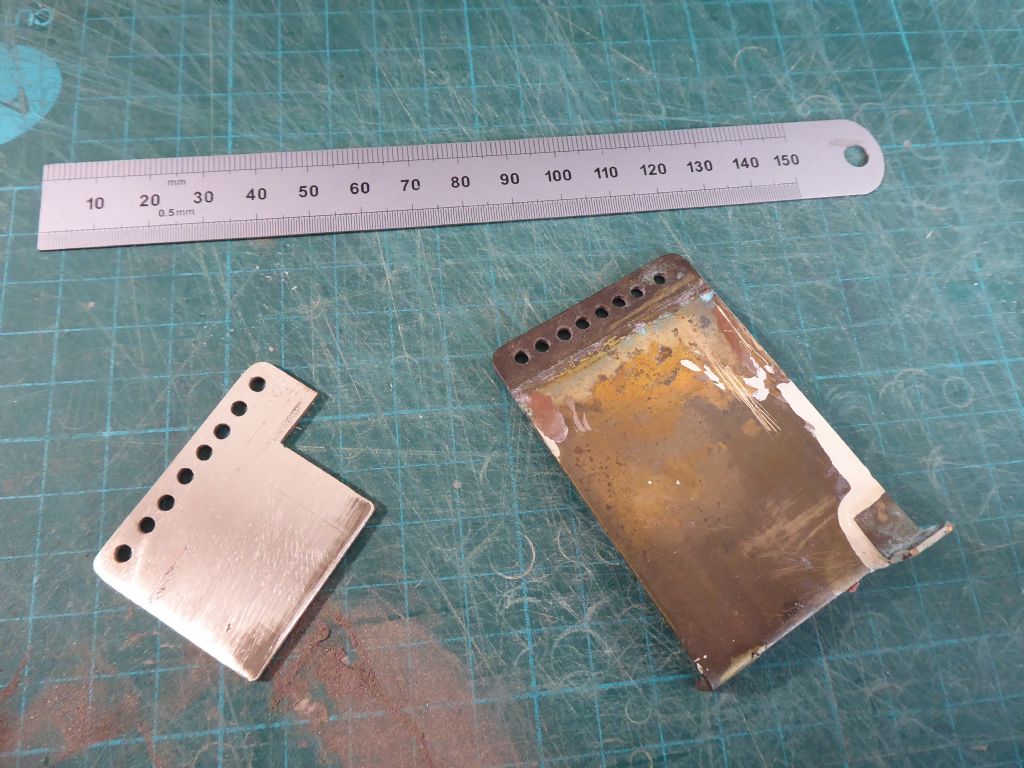
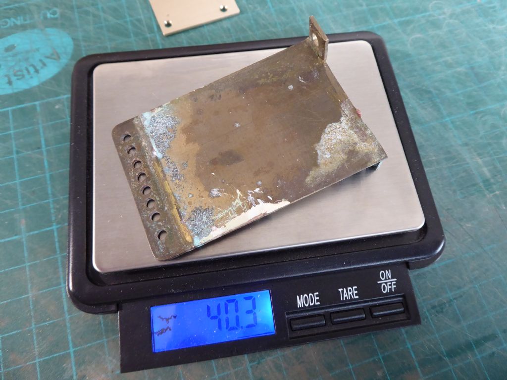
The original on the right with soldered-on feet, a paint run, tarnish and some surface corrosion causing de-zincification. Well is has suffered at least 45 years of neglect!
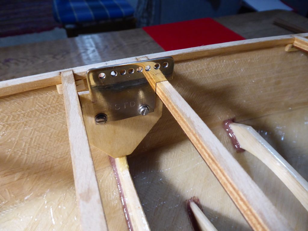
The plates were also much larger than needed for the new arrangements.And porky! The cut-down chainplates came in at 12 grams.
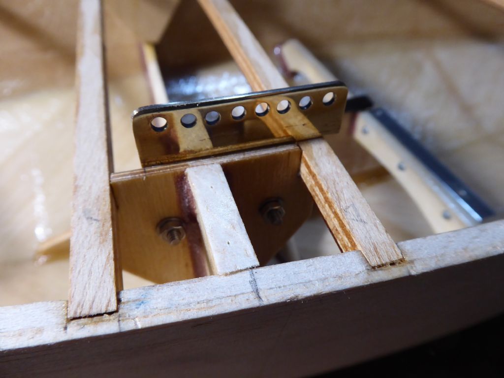
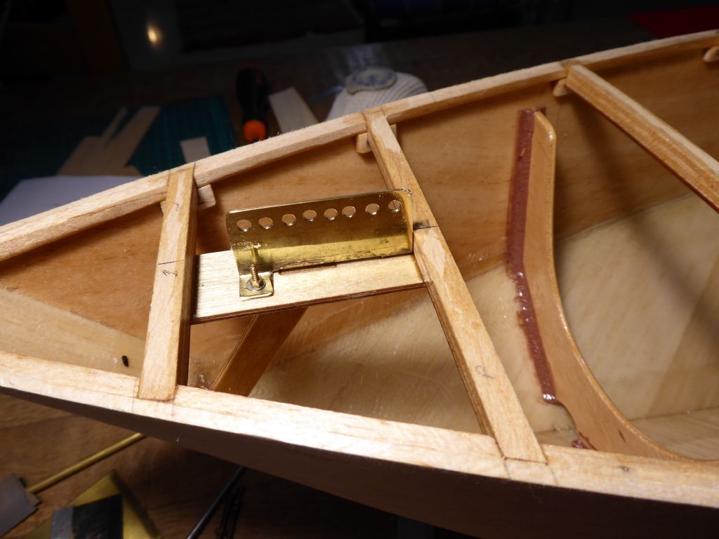
One view of the starboard chainplate. It had to be offset towards the stern as the cap shroud has to be inline with the mast but the lower shroud has to be further aft.
The port chainplate in place.
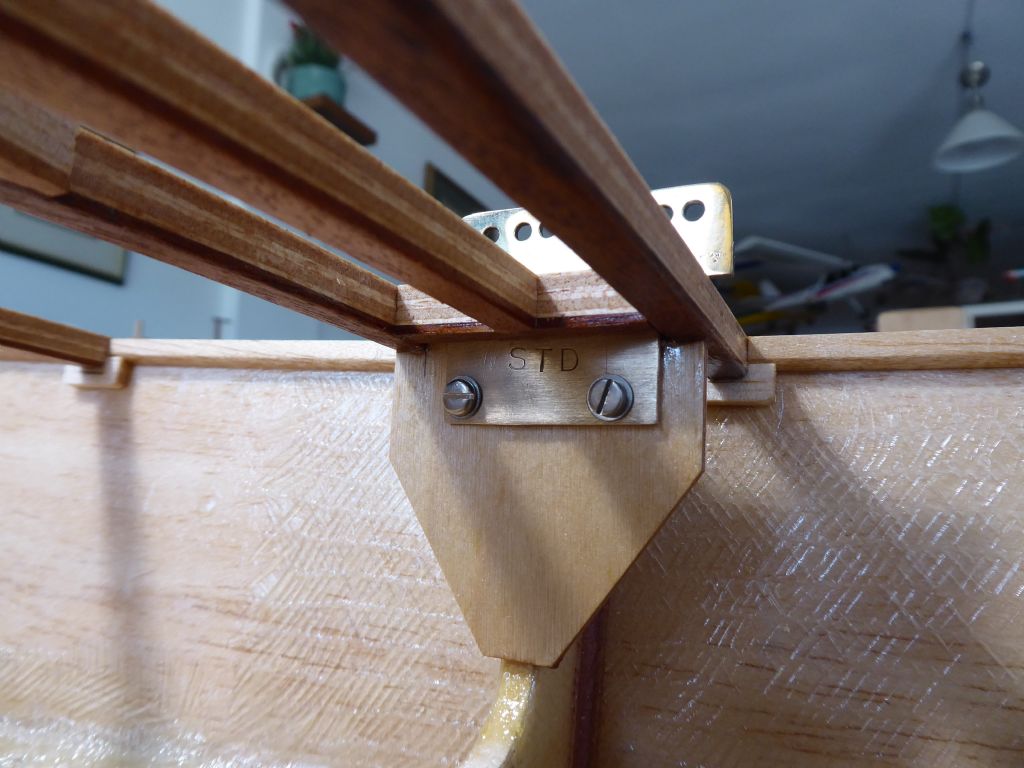
A close-up of the starboard assembly. The fastenings are stainless steel and M3 which is a complete overkill but what I have in stock. Ideally I would use M2 which would still be more than strong enough and look much neater. Anything smaller however and they get a bit harder to handle.
In this photo a short carlin has been added creating a slot and resisting the sideways load from the lower shroud that is angled inwards. The carllin is itself supported by an intermediate beam which effectively creates a ring frame which is strong and very light.I got into the habit of marking components when building model aircraft. Often parts are dry fitted and then put to one side or sometimes sub assemblies built in advance. It is easy to forget "which way up" or "which way around" and if there are choices they can easily be mixed up and holes no longer aligning etc. Here you can see I have stamped STD.
These chainplates are dry fitted for the moment while I work out the sheeting positions. When they go back in for good, I promise I will line up the screw heads!Here is the forestay attachment which is completely original except for the new shine. I had to be quite aggressive to remove all the corrosion spots starting with 320 emery, then 600 followed by 1000 wet and dry done wet. Final polish with Solvol Autosol.
I am now ready to fit the innards and starting thinking about how it is all going to work.
Tim R
27 January 2019 at 17:42 #80855Tim Rowe
Participant@timrowe83142Bit of a gap in the posting due to a technical hitch with my computer. My cloud computing stopped syncing for some reason which meant that the photos that had not been uploaded did not appear as thumbnails in my folders and could only be identified by their file number. That made adding to the album doubly difficult. Semi fixed now by uninstalling OneDrive so everything is now on my hard drive until I get a proper fix.
Work on the boat has been going on though as I tackle for fiddly bits. The deck will stay as beams only for as long as I can get away with it so for the moment, access to the inside is good.
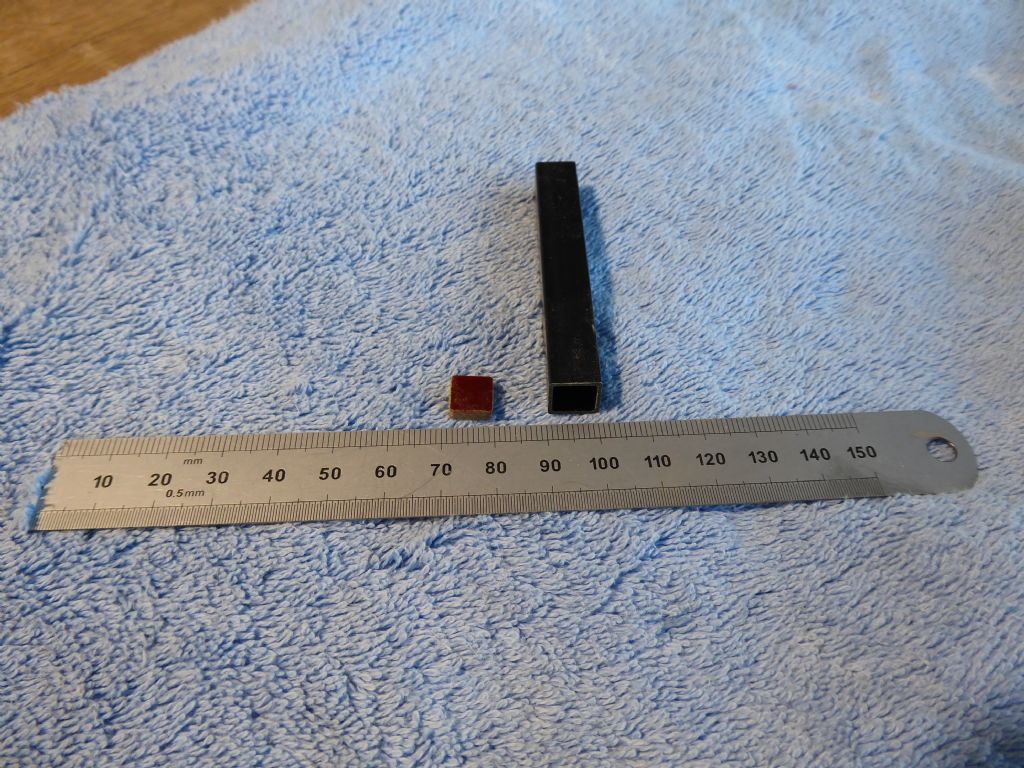
Here is the compression post for the mast which is going to be deck stepped. It is possible to control mast bend much better with a keel stepped mast with a ram or adjuster at deck level. This is not a racing yacht and so I can live without that and have one less hole on the deck to make waterproof. The post is square carbon tube 12mm x 12mm with a 1mm wall. Super light and super strong because it will also serve (I think) as an anchorage point for the sheets.
At the bottom end, the post will be fixed by a small pad made from a piece of 3mm Tufnol shown here on the left.
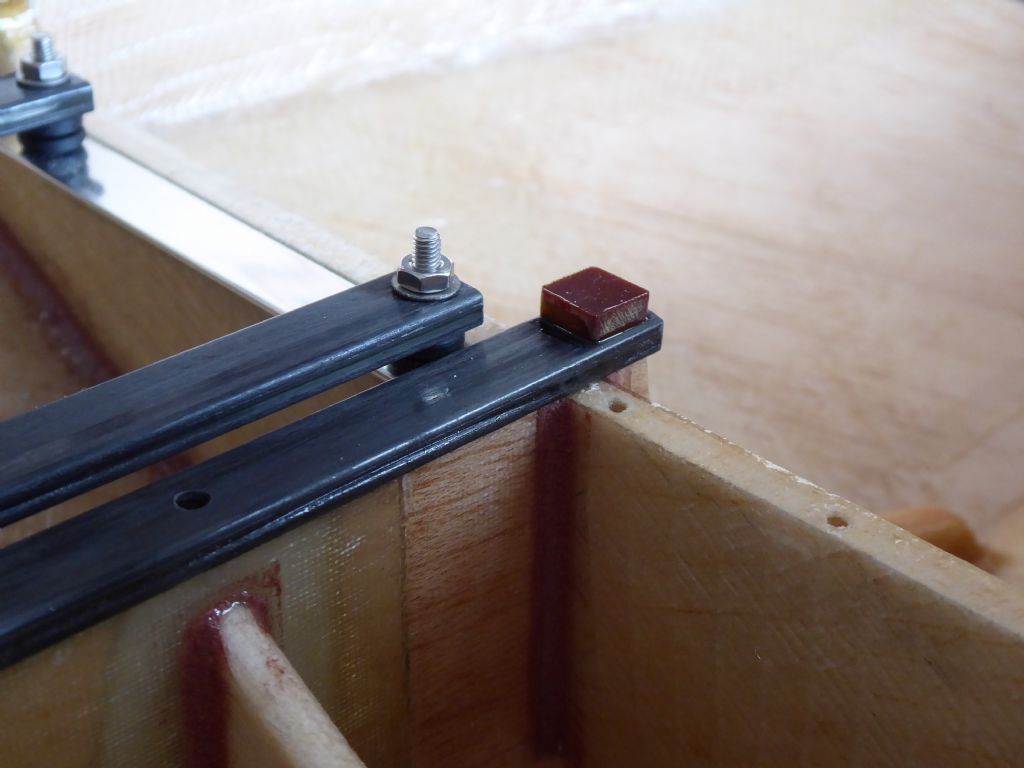
Here the Tufnol pad is glued to the carbon fibre mast step which provides a nice secure register.
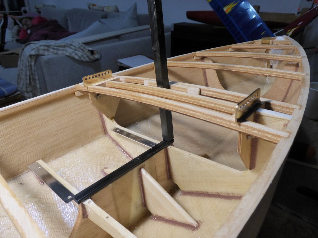
This is a trial fit for the compression post before trimming to deck level.
And this is how it is retained at deck level. The slot is made up from offcuts from the deck beams. The slot will become redundant when the deck is on but serves a useful purpose while sorting out the sheeting etc as it can be taken out and replaced with ease while setting up.
The mast compression post is the last component that ties all the transverse rig loads to the keel. The rest of the boat more or less hangs on this structure.
Tim R
27 January 2019 at 21:28 #80857 Ray Wood 3Participant@raywood3
Hi Tim,
Are you using a drum winch & running line? Or the lever arm servos? My winch experience with the barges has not been great, but works fine on the Dragon Flite 95.
Bitter cold here was going to check out dinghy on the beach but thought better of it 😃
Regards Ray
27 January 2019 at 22:31 #80858Tim Rowe
Participant@timrowe83142Hi Ray
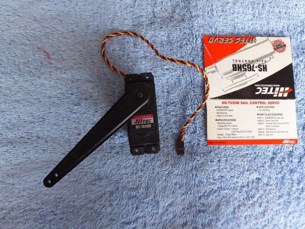
I bought a Hitec HS-765HB lever arm winch. There was no manual and searching the web reveals not a lot on how to set them up. I have learned a few things about orientation of the arm and of course it takes up quite a lot of room in the boat. I shall muddle through ok.
From my experience with a winch on the IOM I think one of the secrets is to have a line tensioner so that even in very light winds, or when the sails are flapping, there is some tension which hopefully will stop the tangle.Coldish here (single figures) but a lot of wind. If it stays like this I will have to think about a No 3 rig.
Just looked up the Dragon Flite 95 as I had not come across one before. Do you have a class near you? Nice boat.
Tim R
27 January 2019 at 22:58 #80859 Ray Wood 3Participant@raywood3
Hi Tim,
Yes the DF95 has really taken off here, it's a poor man's 1 metre class around £300 many clubs have adopted for racing. Much cheaper than a Brit Pop £1600 for a hull 😯
Regards Ray
goes like a rocket !!
Edited By Ray Wood 2 on 27/01/2019 22:59:39
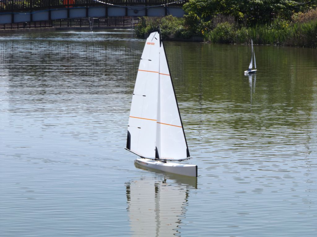
28 January 2019 at 16:07 #80862 Ray Wood 3Participant@raywood328 January 2019 at 16:52 #80864
Tim Rowe
Participant@timrowe83142Hi Ray
Looking very pretty and a nice stretch of water too. Where is it? You are right about the IOM, they are expensive. My second-hand Topiko cost 600 euros but did come with a new Graupner Regatta winch and batteries, radio gear, No 1 and No 2 rigs and a stand. It is measured and certified which helps.
When I get Galileo on the water I shall be interested to see the comparative performance. I predict the IOM will win out on all counts except downwind in heavy weather. The Topiko is known for its tendency to submarine (the next design development aimed to improve this) but Galileo planes quite readily and of course this bring the apparent wind down.This is the lever arm servo I am using. Quite a beast but nice a quiet in operation. In the box comes this long arm plus a conventional arm and a disc. No fitting for the end of the arm and no instructions which was a surprise considering it is a special servo and some of the installation requirements are very important.
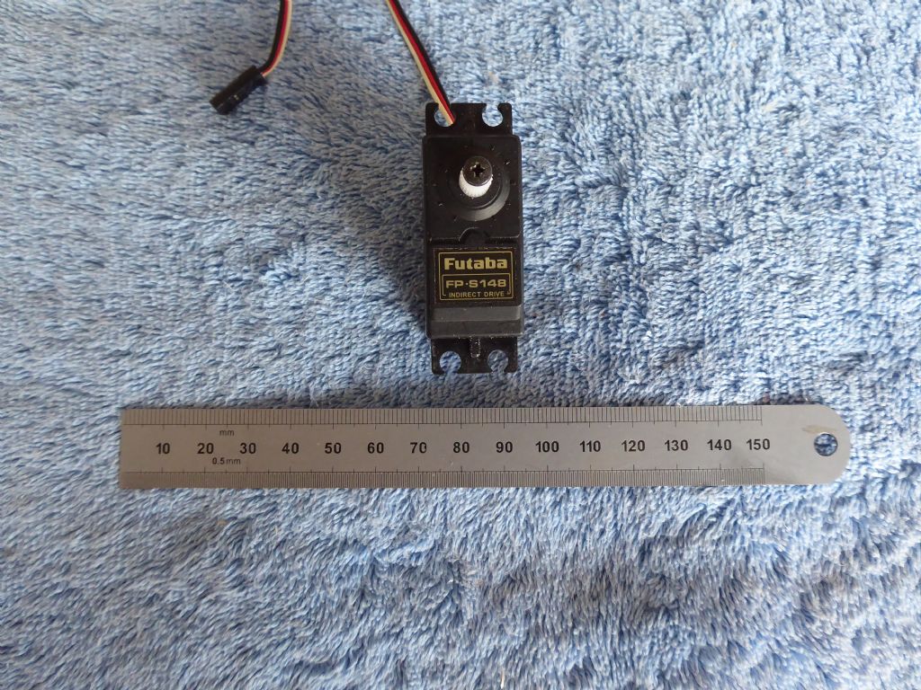
The steering servo is a Futaba FB-S148. I have a good number of servos "in stock" and chose the S148 over the 3003 because it is supposed to have better resolution and repeatability. The 3003 is slightly stronger but the S148 is more than man enough anyway.
When I am installing equipment whether in boats or aircraft I like the various components to be accessible and dismountable. Servos can fail and who knows whether I might swap out the lever arm for a drum winch one day.
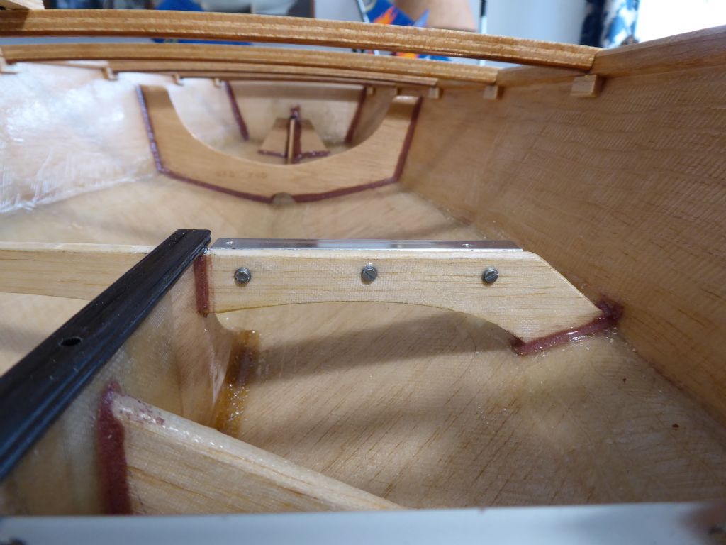
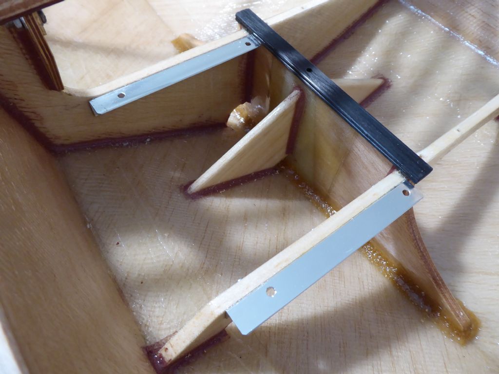
Lightweight aluminium angle is glued and bolted to the keel support webs and on these I can bolt servo rails at whatever spacing is required.Here the two of them are in place and they are part of the permanent structure. It is just possible to make out that the webs are balsa sandwich. Dead easy to cut, super lightweight and very strong.
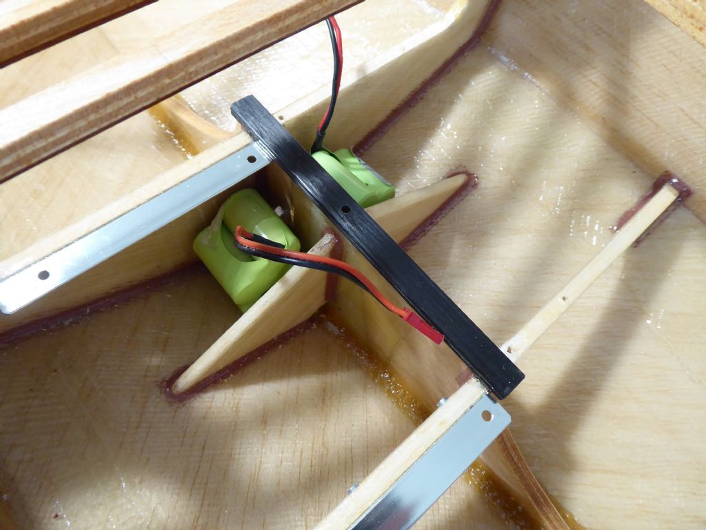
In this photo I have a dummy run of the battery location. These are 5 cell NiMH batteries giving 6v and are the same as I use on the IOM which has a significantly larger rig. They are buggy style batteries stacked two on three which makes them quite compact. Here, two of them fit perfectly alongside the keel box which is ideal as far as weight placement is concerned but they would need to be held of the hull to keep them out of the inevitable bilge water. It means they are not so accessible for charging although I might bring a charging lead into a small screw top pot so they can stay put most of the time. Alternatively I may put a single battery in the pot so it can be taken out for charging.
The decision can wait as I have not yet decided on the hatches. At the moment I am leaning towards self adhesive deck patches as they tend to be more reliable in keeping the water out and I don't like hatches with coamings on this type of boat.
I am quite happy that it is evolving and makes an interesting change from working with plans.
Tim R
28 January 2019 at 17:40 #80865 Ray Wood 3Participant@raywood3
Hi Tim,
Those lever servos are very good I have 2 in my barge Veronica one on the main and the other controls the sprit via the vang. I sail at Bluewater shopping centre in Kent, the Chantry mb club, wind is flukey as it's in a quarry, my wife likes the venue for some strange reason??I
I made some cork lined hatches on my 30" sailing barge, photos in my album, seems to work 😁
regards Ray
31 January 2019 at 19:19 #80895 Ray Wood 3Participant@raywood3
Hi Tim,
Sonata E 😀 are you going brushless? My Raven sloper is coming on 😁
Regards Ray
Edited By Ray Wood 2 on 31/01/2019 19:20:33
31 January 2019 at 19:33 #80896Tim Rowe
Participant@timrowe83142Haha Ray
You have been visiting the dark side!! Yes definitely brushless. Had some fun with the spoilers but they work well now.
I am looking forward to getting it finished but Galileo first.Tim R
-
AuthorPosts
- Please log in to reply to this topic. Registering is free and easy using the links on the menu at the top of this page.
Code of conduct | Forum Help/FAQs
Latest Replies
Home › Forums › Sailing Models › Topics
-
- Topic
- Voices
- Posts
- Last Post
-
-
The new journey begins
1
2
3
Started by:
 mick east
in: Build Blogs
- 9
- 52
-
1 day, 2 hours ago
 mick east
-
New Website Forum – Discussion Topic
1
2
…
7
8
Started by:
 Colin Bishop
in: News and Feedback
- 20
- 183
-
1 day, 8 hours ago
 Colin Bishop
-
Tin Plate Clyde Puffer
1
2
…
7
8
Started by:
Len Morris 2 in: Scratch build
- 12
- 177
-
1 day, 9 hours ago
 Richard Simpson
-
Puffer advice
Started by:
 Alasdair Allan
in: All things floating
- 4
- 20
-
1 day, 11 hours ago
Len Morris 2
-
Todays Boating
1
2
…
200
201
Started by:
 ashley needham
in: All things floating
- 83
- 5,002
-
1 day, 20 hours ago
 ashley needham
-
Kempton steam open days incl boats
Started by:
 ashley needham
in: All things floating
- 2
- 7
-
1 day, 20 hours ago
 ashley needham
-
Purchasing Kits.
Started by:
Michael Cole 8 in: Building Kits
- 6
- 15
-
2 days, 18 hours ago
 ashley needham
-
Kempton Park Steam Engines
Started by:
 Colin Bishop
in: Shows and Events
- 1
- 1
-
3 days, 5 hours ago
 Colin Bishop
-
another Clyde Puffer
1
2
Started by:
mmcp42 in: Scratch build
- 7
- 45
-
3 days, 7 hours ago
mmcp42
-
Wanderer III
Started by:
grich101 in: Scratch build
- 4
- 5
-
5 days, 17 hours ago
 Ray Wood 3
-
Two more of my old models gone
Started by:
Bob Wilson in: Static modelling
- 1
- 1
-
6 days, 4 hours ago
Bob Wilson
-
Two more of my old models gone
Started by:
Bob Wilson in: Static modelling
- 1
- 1
-
6 days, 4 hours ago
Bob Wilson
-
May 2024 issue not in the archive?
Started by:
mmcp42 in: News and Feedback
- 2
- 5
-
1 week, 2 days ago
mmcp42
-
My Clyde Puffer
1
2
…
9
10
Started by:
James Hill 5 in: Scratch build
- 17
- 241
-
1 week, 3 days ago
Len Morris 2
-
Wild Duck meets Eventide
1
2
Started by:
Tim Rowe in: Scratch build
- 5
- 30
-
1 week, 4 days ago
 Tim Rowe 1
-
Ben Ain
1
2
3
4
Started by:
 Richard Simpson
in: Steam powered models
- 8
- 99
-
1 week, 4 days ago
 Richard Simpson
-
getting the boat to pond
Started by:
 Alasdair Allan
in: All things floating
- 3
- 8
-
2 weeks, 1 day ago
 ashley needham
-
MFA Motors ceasing business
Started by:
 Colin Bishop
in: All things floating
- 3
- 3
-
2 weeks, 5 days ago
 ashley needham
-
HMS Glory
Started by:
 Colin Miller
in: Build Blogs
- 4
- 18
-
2 weeks, 6 days ago
 Colin Miller
-
ss Miltiades 1901
Started by:
 Colin Bishop
in: Scratch build
- 2
- 3
-
3 weeks ago
 Colin Bishop
-
Amati j class yacht kit
Started by:
 ashley needham
in: Buy/Sell or Trade
- 4
- 6
-
3 weeks, 1 day ago
 ashley needham
-
North West Model Shipwrights Society
Started by:
Bob Wilson in: Club News
- 6
- 17
-
3 weeks, 3 days ago
Bob Wilson
-
ballasting a paddle steamer
Started by:
 Alasdair Allan
in: All things floating
- 5
- 17
-
4 weeks ago
 Colin Bishop
-
Aerokits pt boat bulkhead plans wanted
Started by:
Roo Hawkins 1 in: All things floating
- 1
- 1
-
4 weeks ago
Roo Hawkins 1
-
building a display case
Started by:
 Alasdair Allan
in: All things floating
- 5
- 17
-
1 month ago
 Colin Bishop
-
The new journey begins
1
2
3
-


