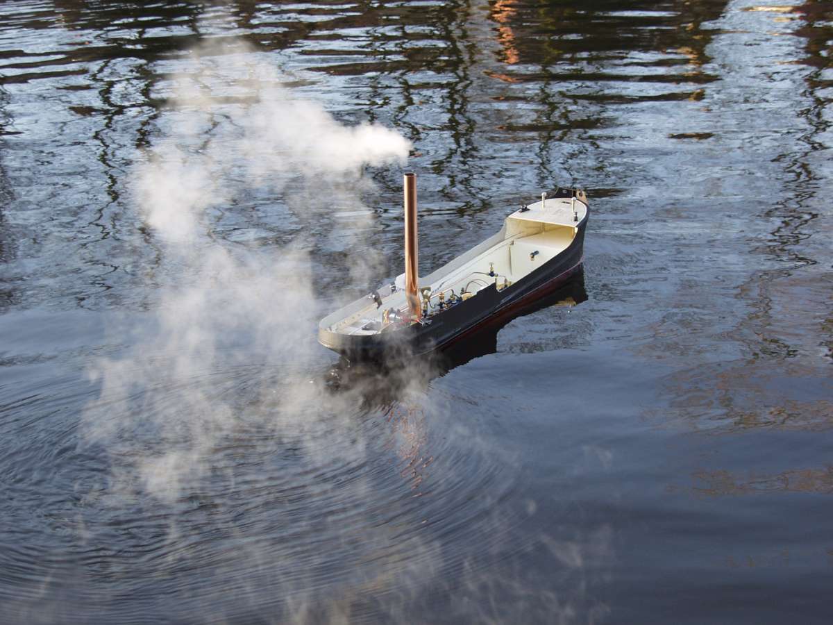
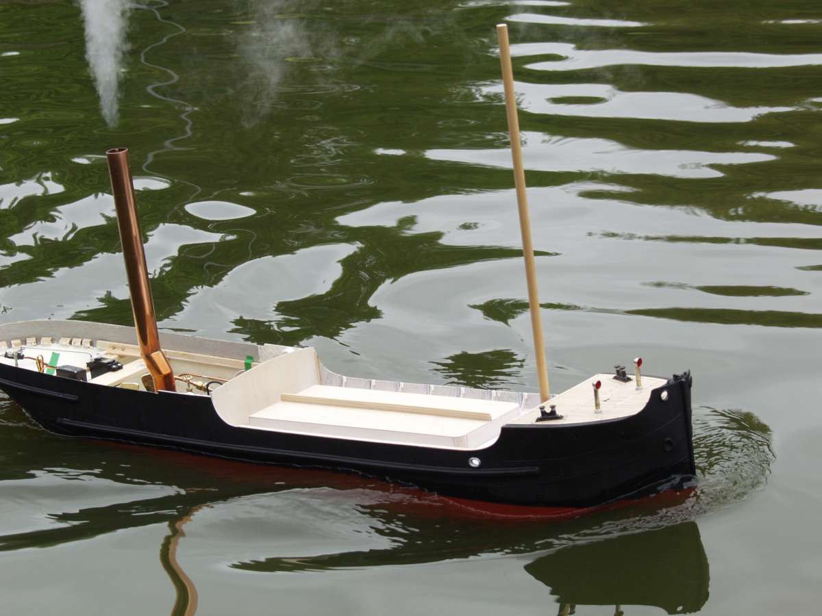
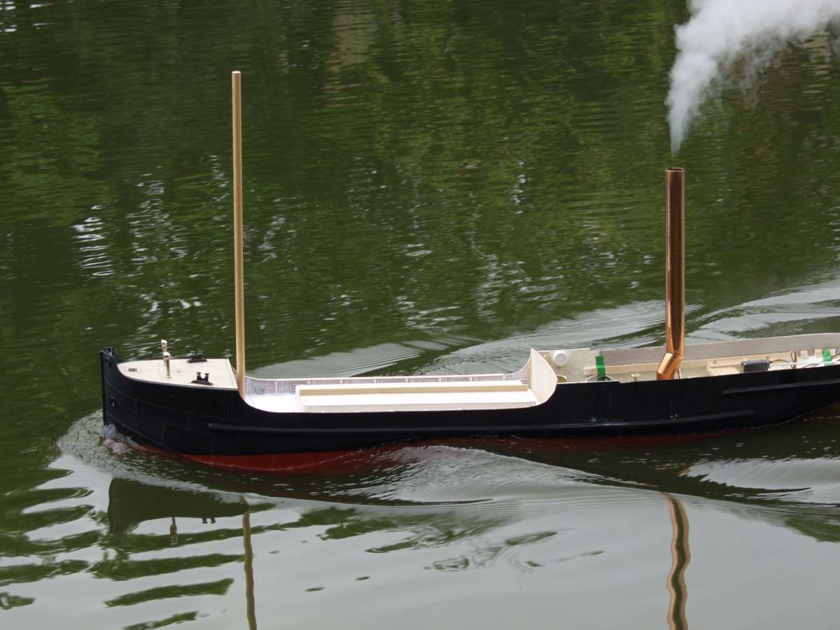
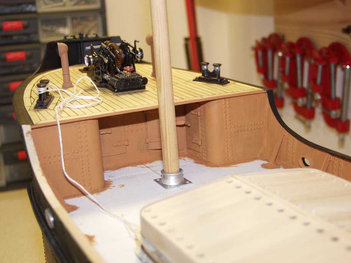
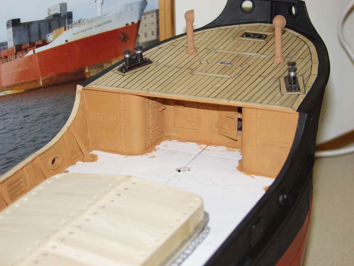
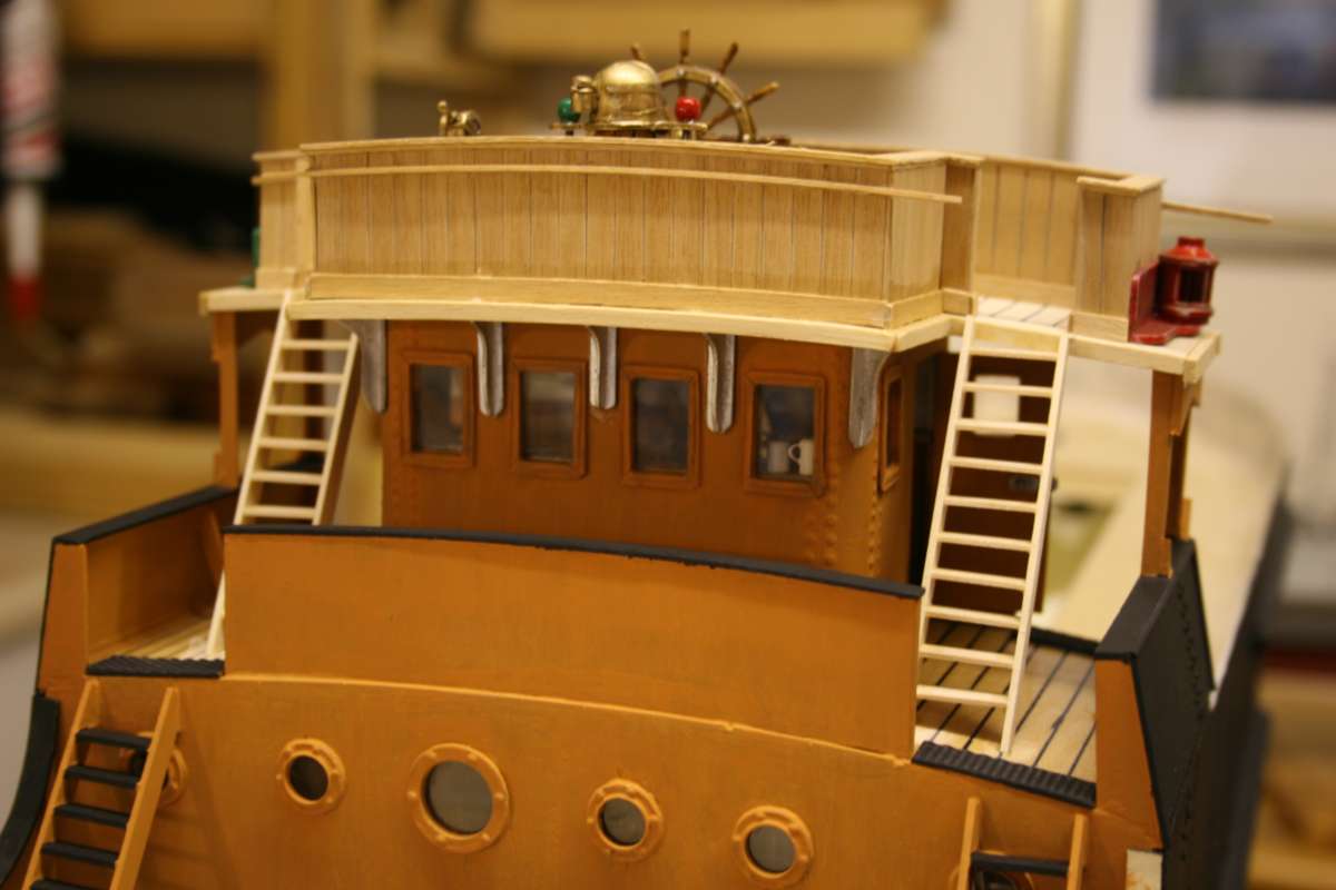
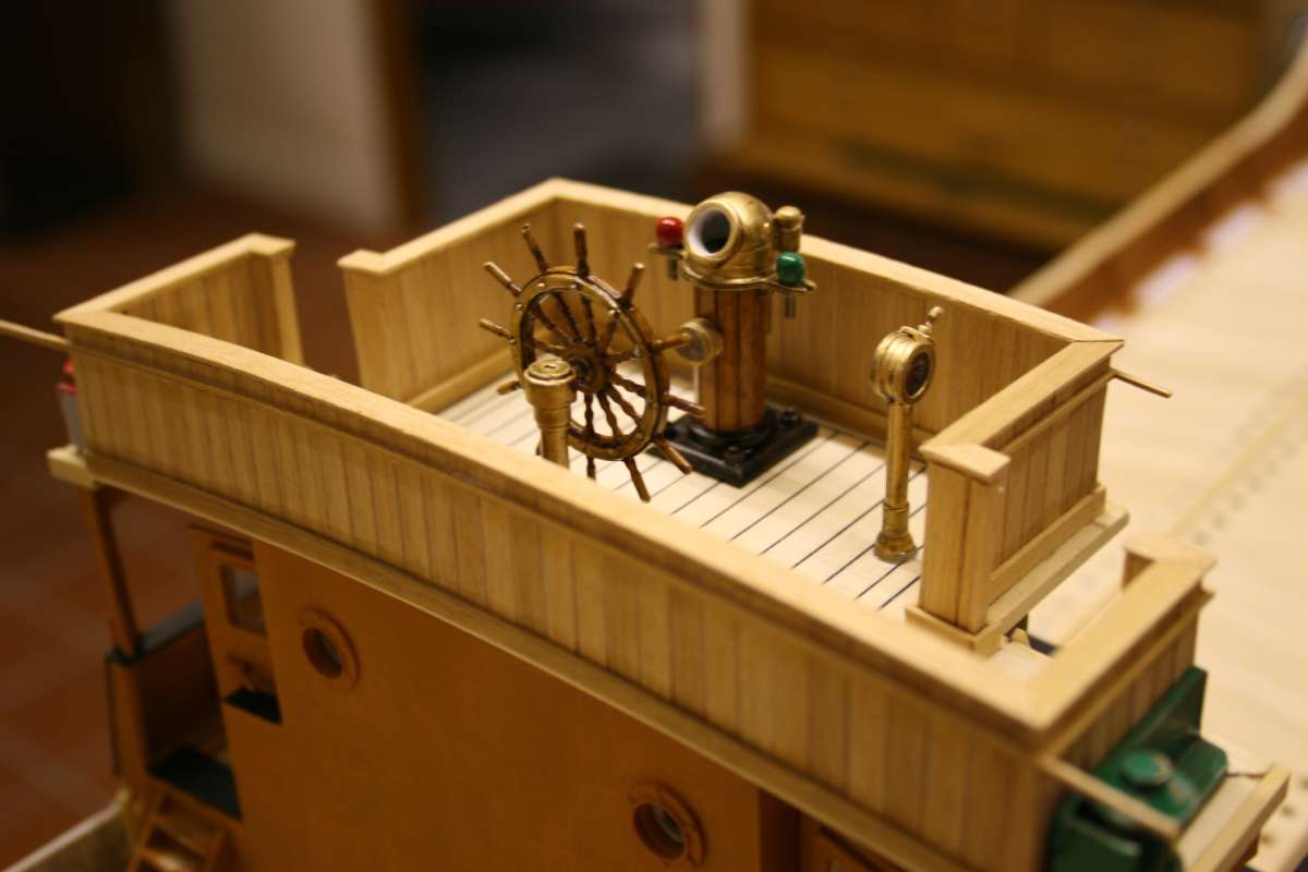
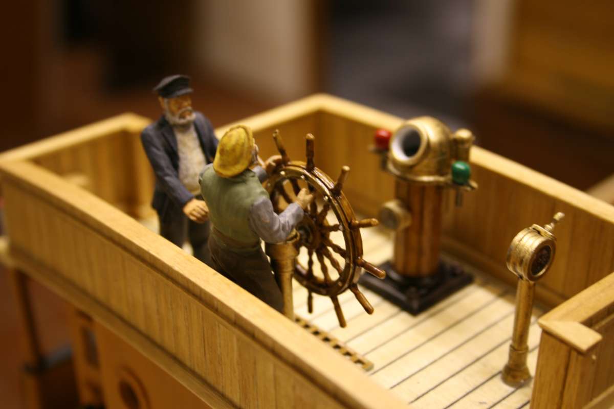
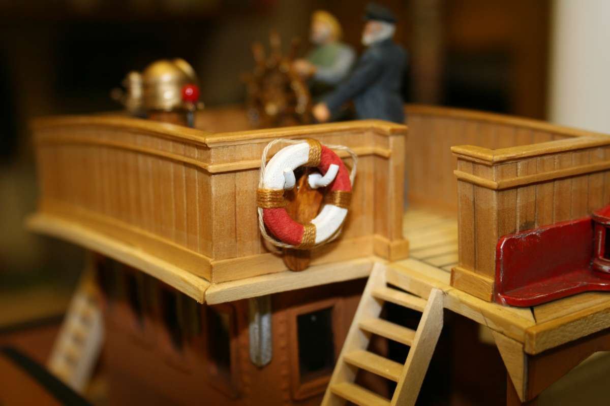
Ben Ain

Advert

Ben Ain

Home Forums Steam powered models Ben Ain

Viewing 25 posts - 1 through 25 (of 85 total)
  • Author
    Posts
  • #118339
    Richard Simpson
    Participant
      @richardsimpson88330

      Bubbling away in the background is a build that has taken me now around 24 years.  I am actually on the final straight now so thought it might be worth posting some pictures.

      First of all a word of warning though.  I started with a Mount Fleet Kit with the intention of fitting a steam plant.  My real enjoyment with modelling though is adding detail and realism so I ended up making two very basic errors with the build.  First up I added far too much delicate detail so the finished model is way too fragile to be a practical operational model.  Secondly I made a complete mess of the original ballasting estimates and, instead of playing around with removeable ballast to start with, I permanently bonded a large steel plate into the bottom of the hull.  The end result was that the final model sits way down to its maximum depth and would be far too risky to put on the pond.  The plate cannot now be removed easily and anyway, if I did I am still concerned that the excessive detail will be too vulnerable.  Consequently is it now sat in a glass case.  On the plus side I can share some of the additional detailing work I did during the build and how I arranged the steam plant.  On the minus side this model will never see water again, however even that gives us all something to learn from and, at the end of the day I still have a nice display model in a glass case.

      The majority of this thread will be a selection of old pictures with one or two old notes I put together.  Feel free to interject with comments or questions, there are no rules, it is simply a collection of stuff that may be of use, in particular to people such as our team of Puffer Builders!

      Advert
      #118342
      Colin Bishop
      Moderator
        @colinbishop34627

        Look forward to it Richard, I remember some of your photos from years ago.

        Colin

        #118343
        Richard Simpson
        Participant
          @richardsimpson88330

          We’ll start off with a couple of the initial hull assembly,   stern frame, shaft, rudder bearing and bilge keel etc.

          23-01-04-06BenAinConstruction4

          23-01-04-09BenAinConstruction7

          23-01-04-08BenAinConstruction6

          23-01-04-04BenAinConstruction2

          #118344
          Richard Simpson
          Participant
            @richardsimpson88330

            The fore deck was one of the earliest additions.  I didn’t like the supplied ply overlay so I planked the deck myself from 5mm x 1mm pear, separated by 0.5mm plastic spacers then the caulking was PVA mixed with black powder paint, painted on then rubbed down.

            23-02-04-09BenAinConstruction9

            20-05-04-03BenAinConstruction12

            With the fore deck in place and the main deck bearers I knew what space I had for a feed tank so that was built from plasticard and fixed in place.  Filling is through a removeable deck vent.

            20-05-04-12BenAinConstruction16

            21-08-04-01BenAinConstruction20

            At the same time cabin lights were added by fitting grain of whaet bulbs inside paint tin lids.  To get an oil lamp glow 12V grain of wheat bulbs were used but they will be powered from 6V.

            21-08-04-02BenAinConstruction21

            #118345
            Richard Simpson
            Participant
              @richardsimpson88330

              Externally the hull was sprayed with a primer then rivet heads were added to the plating by applying spots of cyanoacrylate gel.  I don’t know how many hours it took, I lost count.

              21-08-04-06BenAinConstruction25

              Internally the entire hull was pained with radiator enamel, wooden bearers were added for the steam plant and the aforementioned metal plate was sat in a bed of liquid resin between the bearers.  Not one of my best ideas.

              20-05-04-04BenAinConstruction13

              20-05-04-01BenAinConstruction10

              I could then start playing around with the steam plant arrangement.

              20-05-04-15BenAinConstruction19

              #118351
              Richard Simpson
              Participant
                @richardsimpson88330

                One thing I wanted to do was to test the model on the water as soon as possible.  This was before the main deck was even fitted to give me time to make adjustments to the layout before the deck was fitted.  The first sea trial was with temporary servo mounts and things held in place with bits of tape and cable ties.


                19-12-04-01BenAinConstruction30

                19-12-04-08BenAinConstruction37

                19-12-04-39WittonParkBenAin31

                19-12-04-31WittonParkBenAin23

                19-12-04-10WittonParkBenAin2

                #118352
                Richard Simpson
                Participant
                  @richardsimpson88330

                  Putting in place the few things I learned from the first sea trials i then added the main deck and built the basic box structure of the hatch so I could do another sea trials with the deck in place.  Things were a lot more located in the final place in the model this time.

                  18-01-05-12BenAinConstruction71

                  15-05-05-19Witton ParkBenAin94

                  15-05-05-17Witton ParkBenAin92

                  15-05-05-12Witton ParkBenAin87

                  15-05-05-03Witton ParkBenAin78

                  #118353
                  Richard Simpson
                  Participant
                    @richardsimpson88330

                    So with the second sea trials done successfully and everything working well I could progress the model.  The ply pre-printed hatch board overlays were replaced with individual boards that had to be drilled for the handles and the foc’s’le bulkhead was built off the model as a seperate peice.  The trick with this was that the main deck angle was slightly different to the foc’s’le deck angle so getting those angles perfect while still ensuring that the bulkhead was perfectly vertical was tricky.  Then the tricky bit was to fit the unit as the opening was narrower than further in!  I got there in the end was was very pleased with the fact that there was no gap anywhere.

                    The deck was covered with heavy paper overlays cut to deck plate sizes and a fine brass tube was sharpened at the end and very gently pressed into the edge of the paper.  This gace a reasonable representation of flush rivets around the deck plates.

                    24-09-05-03BenAinConstruction89

                    02-06-05-04BenAinConstruction74

                    I also fitted the bulwark stays at this point using a thinner wood section that the kit part and enhancing the stays with small pieces of Evergreen angle at iether ends.  Another job that required buckets of patience but worth it in the end.   Bulkward capping rails were also added from stripwood along the straight lengths and lite ply around the curved sections.

                    23-09-05-06BenAinConstruction83

                    23-09-05-01BenAinConstruction78

                    02-06-05-07BenAinConstruction77

                    #118354
                    Richard Simpson
                    Participant
                      @richardsimpson88330

                      Big bits in place and a first attempt at painting the captain figure.

                      02-06-05-03BenAinConstruction73

                      23-09-05-07BenAinConstruction84

                      I also progressed some of the fore deck detail, building the anchor winch pretty much out of the kit parts.  The vents connect to the feed tank and the port one simply lifts off to fill the feed tank.  The hawse pipes are brass tube passed through the hull and sealed at either end with epoxy so chain can actually be passed through.

                      24-09-05-06BenAinConstruction92

                      24-09-05-02BenAinConstruction88

                      23-09-05-03BenAinConstruction80

                      #118355
                      James Hill 5
                      Participant
                        @jameshill5

                        Hi Richard,

                        Looking at those pictures is an education on it’s own. Thankyou for posting them.

                        I know what you mean about detailing. Once you start, you have to keep going. I scratch built an L M S Duchess loco in 4mm and gave myself no end of problems trying to make detail that had to be on it. Your rivetting detail on the hull is exceptional. What mine will look like when it’s painted, heaven knows. I think it will need improving in places.

                        Jim.

                        #118356
                        Richard Simpson
                        Participant
                          @richardsimpson88330

                          Thanks Jim.  The paint process is all part of the effect and just as important as the riveting.  I think a common mistake is to try to obtain a perfect finish when, in reality the paint job on the hull is as a result of many years of patching up.  Consequently it shows a whole range of textures and finishes as well as varying levels of fading across the hull.  The first step I took towards this was a base colour that was matt black enamel applied with a small flat brush.  This leaves marks similar to the wide brush strokes left on a real hull.  I also mix in very small spots of satin black during the process to slightly vary the finish.  There is more weathering yet to do to the hull, which will be right at the end.

                          21-08-04-03BenAinConstruction22

                          21-08-04-04BenAinConstruction23

                          21-08-04-05BenAinConstruction24

                          #118357
                          Richard Simpson
                          Participant
                            @richardsimpson88330

                            Probably the biggest deviation from the kit design was the fact that I wanted the bridge section to be removeable to give the best possible access to the steam plant.  I consequently had to completely rethink how the bridge was going to be attached.

                            I decided the best way was to have a forward bulkhead and an aft bulkhead that slid into guides, with the bridge built between the two.  The first job then was to create the guides and supports and fit the two bulkheads.

                            05-02-06-06BenAinConstruction103

                            21-10-05-14BenAinConstruction96

                            21-10-05-15BenAinConstruction97


                            When they were in place I could fit the deck between them and build the bridge upwards from that.  Additional stiffening was required to ensure the complete unit was rigid enough to be handled as a seperate peice and maintain its shape.

                            05-02-06-01BenAinConstruction98

                            Then the deck was planked over a light play overlay.

                            05-02-06-11BenAinConstruction108

                            To give me a solid structure that simply slid into the guides.

                            05-02-06-14BenAinConstruction111

                            The remaining bridge structure was simply built onto this peice.  I wanted the rear bulkhead to be one continuous peice right up through the monkey island and the aft bridge sidings for maximum strength and alignment.

                            05-02-06-16BenAinConstruction113

                            05-02-06-17BenAinConstruction114

                            #118359
                            Richard Simpson
                            Participant
                              @richardsimpson88330

                              The build of the bridge module was then a lengthy process over a number of months.  All was fairly straightforward once the structure was put together and the majority of the work was simple building.  One challenge was to ensure that the hull sides matched up perfectly otherwise I would have had an ugly gap.  This was complicated by the fact that the kit was designed with vertical sides whereas I had found a photograph that very clearly showed a noticeable tumble home.  This had to be incorpoarted as well then.  The bridge internals included a lot of scratch built additional detail using a CV Waine book as guidance and a little creativity added in.  The flag locker has paper flags in it, the correct ones of course, painted with matt varnish to seal the inks.

                              116

                              117

                              118

                              122

                              Cables were run through trunking for the navigation lights and an oil lamp for the chart table.

                              126

                              Forward doger added

                              129

                              And final internal details added.  The chart table has a chart of the North Sea on it and a map of the UK is posted on the aft bulkhead.  Steps down to the accommodation have been simulated by painting graded shades onto planks of wood and surrounding it with a handrail.


                              134

                              138

                              And of course the ever important bits of detail

                              133

                              #118379
                              Richard Simpson
                              Participant
                                @richardsimpson88330

                                Further work on the bridge unit included the steps.  I had to decide how to arrange the steps and the obvious method seemed to be to attach them to the bridge bulkhead only.  This way they would lift off with the unit and, hopefully, sit in place when the unit ws fitted.  The steps were supplied as cast white metal items, which were a bit chunky and heavy.  I could have dressed them up but figured it would have taken a long time so better results were likely from scratch building my own from stripwood.  The risers were fitted first using spacers for perfect alignement then steps were added individually, progressing upwards as the glue set.

                                139

                                140

                                145

                                #118380
                                Richard Simpson
                                Participant
                                  @richardsimpson88330

                                  Then, with the steps done, I moved ever upwards.  Next was the monkey island decking, again a lite ply overlay was overlaid with undividual planks.  I modified the caulking process and applied it with a syringe rather than plastered it all over.  A lot less to sand off again!

                                  149

                                  153

                                  156

                                  #118381
                                  Richard Simpson
                                  Participant
                                    @richardsimpson88330

                                    Then time for the bridge sidings.  Because the aft siding is cored by a continuation of the aft bulkhead it is nice and strong and the forward part gains strength from the right angled ends.  Again the supplied pre-printed ply overlay was replaced by individual stripwood planks.  This time a darker wood and each plank was gently rubbed on fine abrasive to remove the sharp edge and create a more pronounced planking.

                                    161

                                    162

                                    165

                                    All finished off with a capping rail of the same wood.

                                    167

                                    #118382
                                    Richard Simpson
                                    Participant
                                      @richardsimpson88330

                                      Navigation lights were fitted next.  White metal items painted up and weathered to look more like a copper item that has been overpainted then chipped away.  The lamps are grain of wheat bulbs and the lamp lenses are painted with Tamiya clear acrylic paint.

                                      170

                                      An access locker actualy hides the electrical connection.

                                      174

                                      176

                                      #118383
                                      Richard Simpson
                                      Participant
                                        @richardsimpson88330

                                        Then more internal detail.  The brass fittings were white metal castings painted with brass coloured enamel paint then coated with a Tamiya clear acrylic smoke to add depth and a slightly glossier finish.

                                        184

                                        186

                                        193

                                        Lifebelts scratch built from wood, string and wire.

                                        197

                                        #118384
                                        James Hill 5
                                        Participant
                                          @jameshill5

                                          Hi Richard,

                                          A great set of pictures showing your construction methods, Thankyou for those. I’ve always found that looking at the way others build, ( whatever the subject ) makes you try and improve your own skills. ( It does with me anyway ). You hope and try to get their superior modelling skills to rub off on you.

                                          On your previous set of pictures I loved the wave pattern the hull made when you were trialling in the water.

                                          Jim.

                                          #118385
                                          Richard Simpson
                                          Participant
                                            @richardsimpson88330

                                            Thanks Jim.  If anyone gets any ideas or inspiration from the pictures then it has been worthwhile.

                                            The engine manufacturer, John Hemmens was interested at the time to see the performance of his engine, the Richmond, ‘V’ twin oscillator, in a substantial sized model.  Consequently he asked me for a few pictures of the model at full speed.  I must admit it went faster than I thought it would.  Way over scale speed but reasuring to know I had plenty of get-me-out-of-trouble reserve!

                                            #118386
                                            Richard Simpson
                                            Participant
                                              @richardsimpson88330

                                              As a final element of detail I added a series of stanchions around the bridge sidings that will eventually hold a canvas dodger.  Again I noticed this in a period picture of the ship I had managed to obtain.  Then it was time to turn attention to the raised quarter deck and, in particular what I was going to do with the accommodation.

                                              199

                                              198

                                              205

                                              First up though was finish the deck detailing such as the rudder chain, the bulwark stays and the aft capstan.

                                              219

                                              223

                                              226

                                              228

                                              231

                                              #118387
                                              Richard Simpson
                                              Participant
                                                @richardsimpson88330

                                                Then the coaming was added to the opening with some gusset plates for strength at the corners.

                                                235

                                                237

                                                One thing I had noticed with this model was that the bollards supplied were not according to either the supplied plan or the CV Waine book plans.  I therefore had to modify them with a suitable base and gusset plate between the bollards to make them correct.

                                                233

                                                #118388
                                                Richard Simpson
                                                Participant
                                                  @richardsimpson88330

                                                  The next big job was to move on to the aft accommodation housing.  The part supplied with the kit was a substantial fibreglass moulding however I wasn’t too keen for a number of reasons.  One, the plate and rivet detail on the sides were perpendicular to the top and bottom so when the unit was sat on the sloped quarterdeck the details were not vertical, Two, getting the base to fit perfectly to the deck without a gap was going to take a lot of fettling and Three, The kit supplied part did not have a camber and I know the real vessel did have a camber on the top of this unit.

                                                  255

                                                  The only solution was to make my own from scratch.  I went for a lite ply covering with an internal softwood frame.  This is the construction.

                                                  238

                                                  241

                                                  243

                                                  245

                                                  I made a little jig so I could cut a consistent camber on the end bulkheads and the intermediate frames.

                                                  246

                                                  247

                                                  251

                                                  253

                                                  With the cambered frames in place the top could be made and bent over them.

                                                  254

                                                  257

                                                  259

                                                  #118394
                                                  Richard Simpson
                                                  Participant
                                                    @richardsimpson88330

                                                    So with the basic box created and fitting very nicely over the coaming it was time to move onto adding the fixtures, fittings and details.  Engine room skylight and the funnel were the first two components, mainly from kit supplied parts, apart from the hatch dogs.

                                                    261

                                                    263

                                                    265

                                                    266

                                                    269

                                                    #118395
                                                    Richard Simpson
                                                    Participant
                                                      @richardsimpson88330

                                                      The supplied aft ladder wasn’t really up to the job so that was replaced with a scratch built one.  The copper is 2.5mm domestic ring main cable.

                                                      281

                                                      A secoin of decking was fitted along with a semi-circular beading around the top edge.

                                                      296

                                                      297

                                                    Viewing 25 posts - 1 through 25 (of 85 total)
                                                    • Please log in to reply to this topic. Registering is free and easy using the links on the menu at the top of this page.

                                                    Code of conduct | Forum Help/FAQs

                                                    Advert

                                                    Latest Replies

                                                    Home Forums Steam powered models Topics

                                                    Viewing 25 topics - 1 through 25 (of 25 total)
                                                    Viewing 25 topics - 1 through 25 (of 25 total)

                                                    View full reply list.

                                                    Advert