The world's leading magazine for all model boating interests
Galileo – A resurrection
Galileo – A resurrection
Home › Forums › Sailing Models › Galileo – A resurrection
- This topic is empty.
-
AuthorPosts
-
3 January 2019 at 13:33 #80517
Tim Rowe
Participant@timrowe83142The story starts 50 years ago when I was 12. I had been sailing my Optimist dinghy for 4 years and became really interested in model yachts. A friend and fellow Oppy sailor shared the same interest and we designed and built a couple of models with a simple geared vane self-steering. They were as ugly as sin but did sail and we had a lot of fun.
Looking towards the next step and venturing into radio control I got talking to a friend of the family who had designed a 50' yacht to be built in aluminium which at the time, on the south coast of England, was novel in both size and material.
Leslie Bewes created a design that many thought was only one step up from ugly as sin and other were not so kind. The beauty in my eyes was that it was hard chine and that sold it to me. Daphne his wife was a skilled carpenter and fitted the boat out. Talented family.
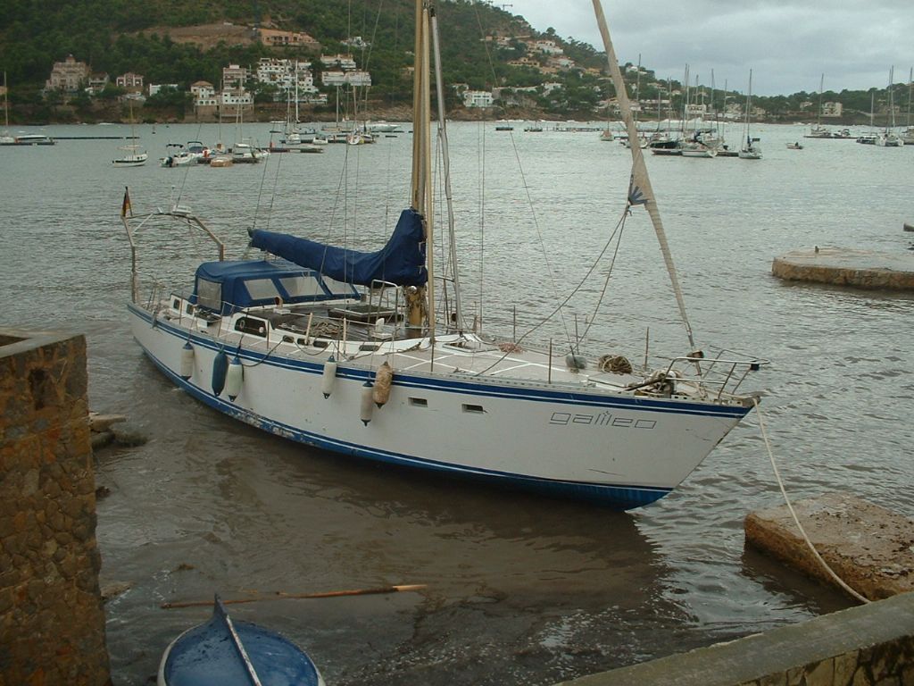
Here is a photo of the full sized Galileo beached in Andratx harbor, Mallorca after a storm about 6 years ago. Some scratches and a few minor dents was the tally but my model suffered a much more horrific fate which I will come onto later.
The yacht was built by Phillip of Dartmouth and all the time it was base on the Hamble river it had burgundy coloured topsides and a light blue non-slip painted deck. The antifouling was white. Overall the boat did look a bit slab-sided and this new colour schemed has stretched things out a bit.
Leslie kindly gave me a copy of the lines plan and sail plan at 3/4" to the foot and off I went. Back then I used to build a lot quicker because I worried about nothing but my pocket money did not go far enough for fancy stuff so I ended up making everything. It did turn out well and was entered in the junior section of the Model Engineering Exhibition. No prizes but I was chuffed enough and it sailed really well even getting on the plane in the right conditions.
Horror story coming up.
Tim
3 January 2019 at 13:33 #9676Tim Rowe
Participant@timrowe83142A 50 year old model yacht comes to life again
4 January 2019 at 17:03 #80537Tim Rowe
Participant@timrowe83142After a while the novelty wore off and other things cropped up like they do. The boat was controlled by a McGregor radio and receiver with 2 proportional channels but I was only using one for the rudder. I was racking my brains to design a simple winch but that failed. Oh how I wish I had thought of a lever arm winch but probably the servos weren't strong enough in those days anyway. The sails were self tacking which was fine for beating to windward but boring on a reach or run without any sail adjustment.
The model survived a number of house moves, now relegated to an ornament until we ended up living on a Dutch barge. One weekend we had to go away and I was not keen on leaving the barge unattended so I arranged for a friend to houseboat sit and yes it was fine if they brought their dog, thinking extra security and the like.
The dog was a nearly full sized puppy Rottweiler and they may be useful for a lot of things but evidently not much good on stairs. Presumably sensing its dinner was in the dog bowl it took the stairs in one and landed on the model. It is the only model I have that has been attacked by a Rottweiler and I don't recommend it.
The deck was smashed through from the main hatch to the deck edge. The topsides were split on the same side and there were four neat holes where the stand had punched up through the bottom.
Now I am not one to throw things away and the sorry state model survived a few more moves with the damaged side always shamefacedly against the wall. One day I will repair it I kept on saying to myself (and everyone else!)Well the time has come and I am taking a bit of a break from building model aircraft and coming back to boats. I always like to have a few projects on the go and currently have a nearly built Elliot Bay Steamer, Bounty's Jollyboat, an own design model yacht, a refurbishment of an International One Metre (IOM) and of course Gallileo. This is my main project until my short attention span says otherwise.
Tim
4 January 2019 at 17:18 #80538 Ray Wood 3Participant@raywood3
Hi Tim,
I have sent you a PM
Regards Ray
5 January 2019 at 11:25 #80546Tim Rowe
Participant@timrowe83142Taking off the cocoon of bubble wrap I gave the boat a critical inspection a couple of weeks ago and decided that a repair was not really practical.
Reason 1.
The deck was in one piece of 1/32" ply and no repair could be invisible. The entire deck would have to be replaced.Reason 2.
The model was all balsa and it never did have sheathing inside or out. Outside would be possible but inside no.Reason 3.
To be honest it was a bit rough inside. Strong yes but if I was going to be doing a lot of work I would always regret not dealing with the internal structure.So it quickly came down to making a new one saving any bits worth saving such as the spars and some of the fittings. The drawings were long gone so the easiest route was to make the new hull over the old one using it as a male mould. Sounds quite easy but in practice there have been quite a few tricky bits to deal with.
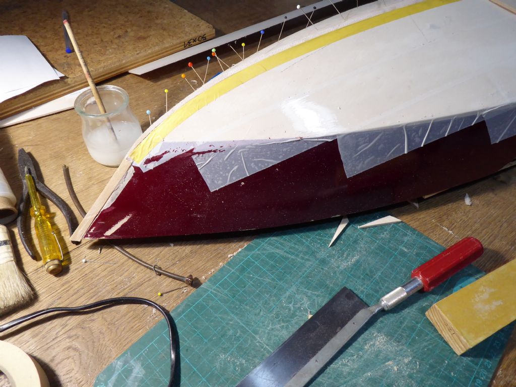
First job was to get rid of all the jagged bits from the damage and cover the old hull with packing tape to use as a release surface. I tried to get it on fairly flat and the tape on the topsides where there are creases was trimmed off later.
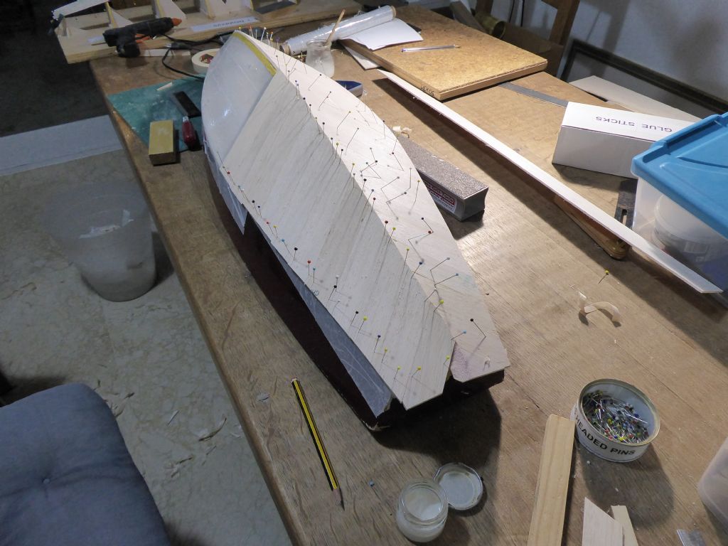
The hull bottom was skinned with 3mm medium balsa cut into 30mm wide planks laid on the diagonal. The original was wrapped in one piece but I reckoned I would have trouble keeping a whole sheet in close contact because the bottom has considerable twist as well as curvature. The diagonal worked well and I was careful to use only just enough glue (aliphatic) sparing applied to the plank edges. In this photo there is a bit to finish at the bow and a little piece missing at the stern.
The bottom sheeting used two and a bit sheets and these were matched as closely as possibly in hardness which makes sanding a whole lot more accurate later. The easiest way to select sheets of equal hardness is to weigh them and choose the closest match.
The planks were left long all around so they could be sanded back at the chine and transom using the old model as a guide.The topsides were a bit easier with curvature but virtually no twist so these could be fitted as single sheets. One advantage for me here is Spain is that the balsa is in metric sizes so the metre lengths were just perfect allowing just a small trimming allowance.
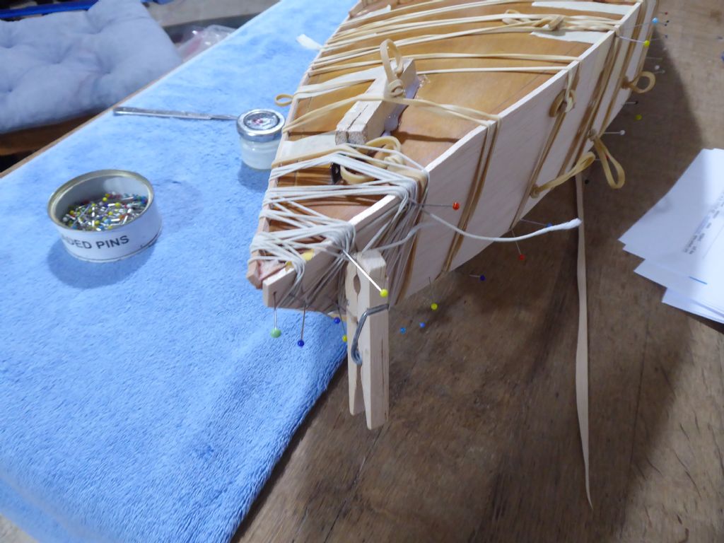
I have a tin full of elastic bands (the tin keeps the light out so they last longer) and it is amazing the clamping force that can be achieved with multiple bands. If one section is being a bit obstinate then simply add more bands. Likewise at the bow where quite a lot of force is needed, the shirring elastic wound round and round does the trick. The glass headed pins are simply there to stop the elastic rolling off the heavily tapered stem.At the extreme point you can see a triangular fillet. The original stem was sanded with a flat and replaced with the fillet. This gives the side sheets something to glue onto and becomes an integral part of the new model.
This part of the operation was surprisingly quick.
Tim
5 January 2019 at 19:47 #80553 Ray Wood 3Participant@raywood3
Hi Tim
It's great that you are bringing some history back to life 😊 I hope you had a serious word with that dog !!
Are you glass clothing the balsa? If your an aero modeller you'll probably have all the materials.
Regards Ray
5 January 2019 at 22:43 #80554Tim Rowe
Participant@timrowe83142Hi Ray
I am using a combination of materials and this time I will be glassing the hull for sure. I have to be careful using epoxy (I hardly use it at all on my aircraft) because I got sensitized some time ago when using it industrially and I only have to look at the glass to get an itch. Doesn't stop the fun though.
On reflection it is probably good that I did not meet the dog. I would have got cross with him and he would then have got cross with me and it was a Rottweiler after all.
Tim
6 January 2019 at 10:05 #80555Tim Rowe
Participant@timrowe83142Here is the aft end of the model encapsulated in the new balsa.
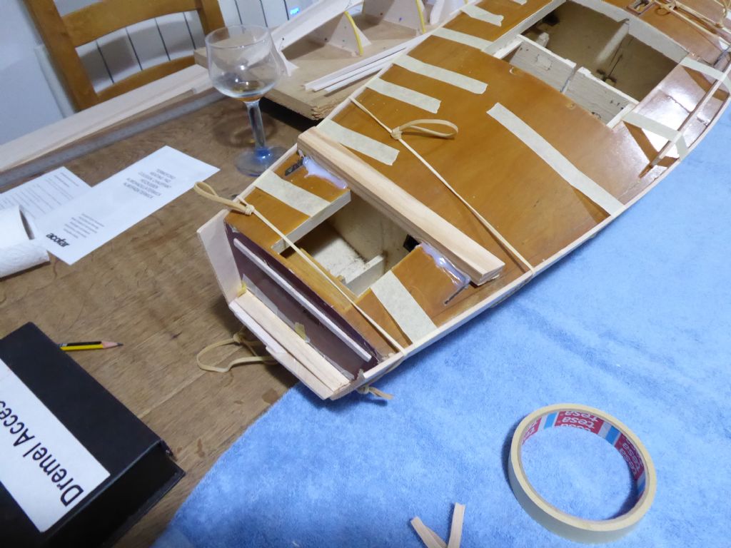
To the right of the picture you can see one of the splits in the deck. This was roughly pushed back into place to maintain the overall shape. The piece of wood hot glued to the deck was to make a level surface for the boat to rest on when working upside down. Otherwise it was rocking on the deck camber.
I left the transom open for the moment. One reason was to allow the new hull to be sprung open to release from the old one. It also makes it possible to insert very thin tapered splines into the gap to wedge the hull off.
The other reason is that the full size was modified at some time to put a "scoop" on the transom giving it a little bit of reverse rake in profile. I thought this an improvement to the appearance as the original was dead plumb and did make the design end a bit abruptly. I left the topside sheets at 1m long which gave me a bit of a trimming allowance to but the rake in by eye later.Tim
6 January 2019 at 12:12 #80557Tim Rowe
Participant@timrowe83142Going back a couple of stages I had to take the old keel out before doing the sheeting.
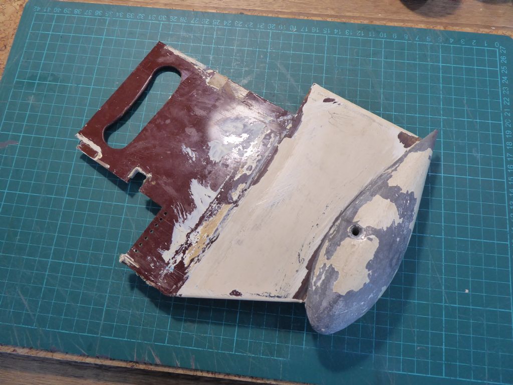
The fin was made from 1/8" Tufnol (oh how I love the smell of cutting and machining Tufnol) and had a built in carrying handle. The square slots took 3/4" square sectioned balsa beams that formed part of a grid located between two bulkheads and which also took the chainplates for the cap shrouds. In those days there was quite a lot of talk about space frames where all the strength for keel and rig loads was in the frames and the hull was to make the boat look nice and keep the water out.
The internal ledge at the fore end of the keel was the mast step. Was drilled with a series of holes so that the position could be changed and fixed. So you can see that all the rig loads did in fact come back to the keel and the rest of the hull was hanging on.I think I used Araldite to fix the Tufnol fin and in the end I had to cut it out using a hacksaw blade. The remains of one of the beams can be seen.
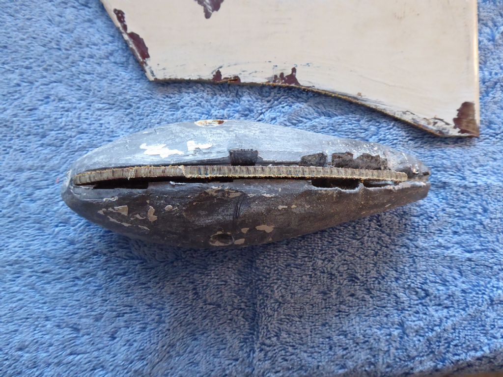
The bulb was a different matter altogether. I fitted a woodscrew as belt and braces but with that taken out – no sign of movement. I then ran the hacksaw blade alongside the Tufnol a good way into the lead and still no movement. A couple of really heavy whacks and still rock solid. That glue did a great job making the screw completely superfluous. Many years later I have a lot of faith in glues.
The only solution was to cut the bulb off and melt it off the Tufnol. That puts paid to re-using it which was my original intention.While talking about the bulb, it was a guess at a suitable streamline shape. By modern standards it is very porky and the low Reynolds Number that model yachts work in prove that much slimmer bulbs have significantly less drag. Furthermore the hull is now 6mm wider, 3mm deeper in the canoe body and about 15mm longer so the displacement will have increased and the original bulb is likely to be a bit light. I will find out later and make a completely new bulb using a calculator package in a future post.
When I built the original model I was aware about wind speeds being non scale. I increased the draft of the scale keel by 1" and had half the bulb depth below this line. In reality this was not nearly enough as I now know. The model was very tender in anything like a moderately strong wind and the inability to ease the sheets (no winch) didn't help. The new model will have a high aspect ration fin with nearly twice the draft. I still do not reckon this will be a heavy weather boat.
Tim
6 January 2019 at 13:09 #80558 Ray Wood 3Participant@raywood3
Hi Tim,
I hope you can keep part of the old yachts fabric in the new one? Maybe the lead bulb? Otherwise this will be a new build 😊
You know the aeroplane restoration folk only need a part with an original serial number on it to build a Spitfire round it !! 😃
Regards Ray. 7 deg cloudy
6 January 2019 at 14:26 #80560Tim Rowe
Participant@timrowe83142Hi Ray
I will be able to keep the deck fittings for the rig. The original mast and boom are fine although the jib boom got broken into little pieces. I still have the original sails for the scale rig although I did make a taller light weather mast that I will need to make some sails for. The lead will be the same but will go liquid first.
The original colour scheme will be the same .The old deck has a lovely patina now and I have already used part of it on a jewelry box I made for my better half.
I think half of the problem getting to grips with this project was the realization that not a lot could be saved. It had however re-awakened many happy memories and will more than compensate. Perhaps it is more like Son of Galileo.
Thanks for your interest.
Tim
8 January 2019 at 13:44 #80592Tim Rowe
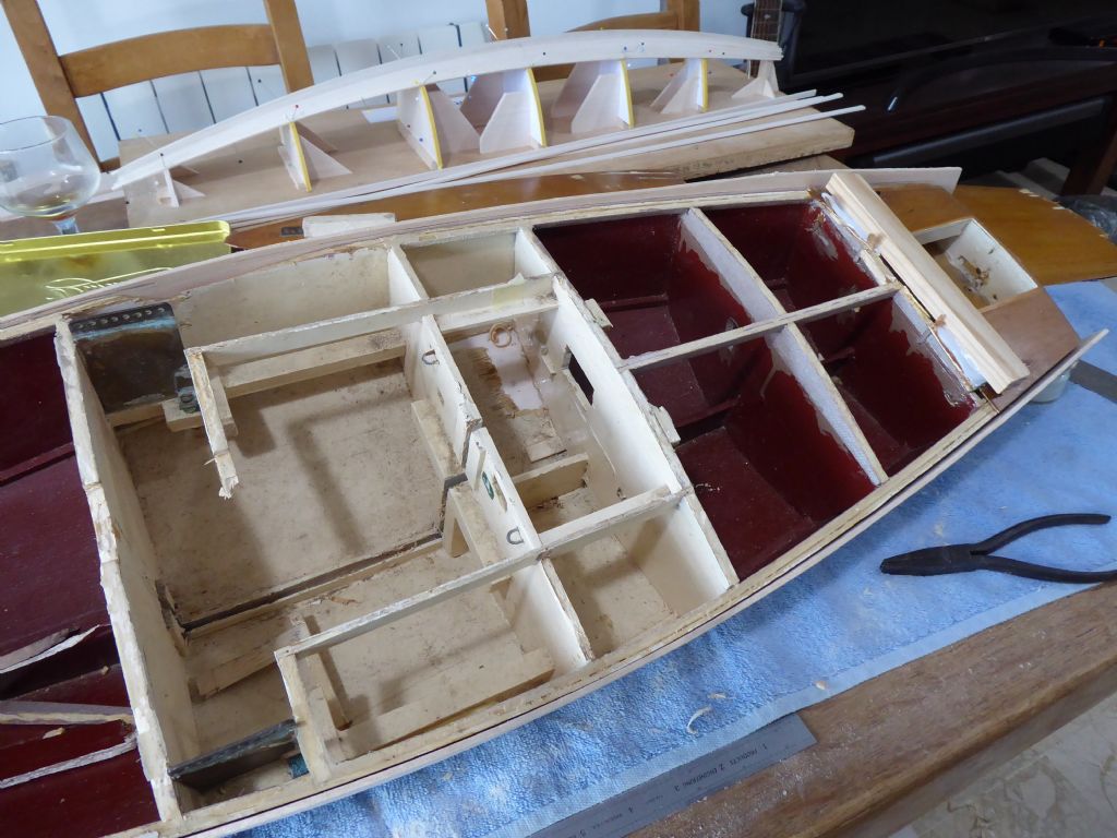
Participant@timrowe83142Well did the new hull separate off the old model? In part yes but it was stuck up on something so the rather more drastic and terminal plan B had to be used.
The old deck was quite easy to remove further exposing the fairly crude construction. THe deck provides the template for the fittings and positions of the bulkheads and was put to one side.
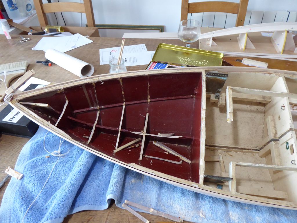
Here is the fore section and the method of fixing the brass chainplates can be seen along with the slot where the keel was cut out with a hacksaw blade.
Here is the aft section (with a sneak preview of another project in the background)
I was amazed how strong the structure was (ok obviously no match for a Rottweiler) as it really took some effort to break out the old hull. It was important to try to get the bulkheads out in single pieces or at least in bits that could be readily glued back together again.
As an exercise, the parcel tape worked very well but some glue had got into the joint at the chines and it was only a few small spots that caused the sticking. Good stuff that glue (Aliphatic)
Tim
8 January 2019 at 20:31 #80596 Ray Wood 3Participant@raywood3
Hi Tim,
Interesting new hull in the background, must be your rg65 ??
The new boat outside the old one is looking good, that's a lot of pegs 😀
Regards Ray
Edited By Ray Wood 2 on 08/01/2019 20:31:36
8 January 2019 at 21:51 #80597Tim Rowe
Participant@timrowe83142Hi Ray
The boat in the background is an own design based on the Sparrow 750 by Bryn Heveldt so a bit bigger than the RG65. I am working up to designing an IOM with a few ideas up my sleeve so I wanted a test bed. The RG65 is a bit to small to make a good comparison so I am building something at 770 mm. What you see is the start of the plug. It is now more or less complete (just needs final sanding) and waiting from some special paint and other materials so I can make a mould.
I should qualify the statement about the tape working well. It would have done if I had been a little bit more careful along the chines as some glue seeped through.
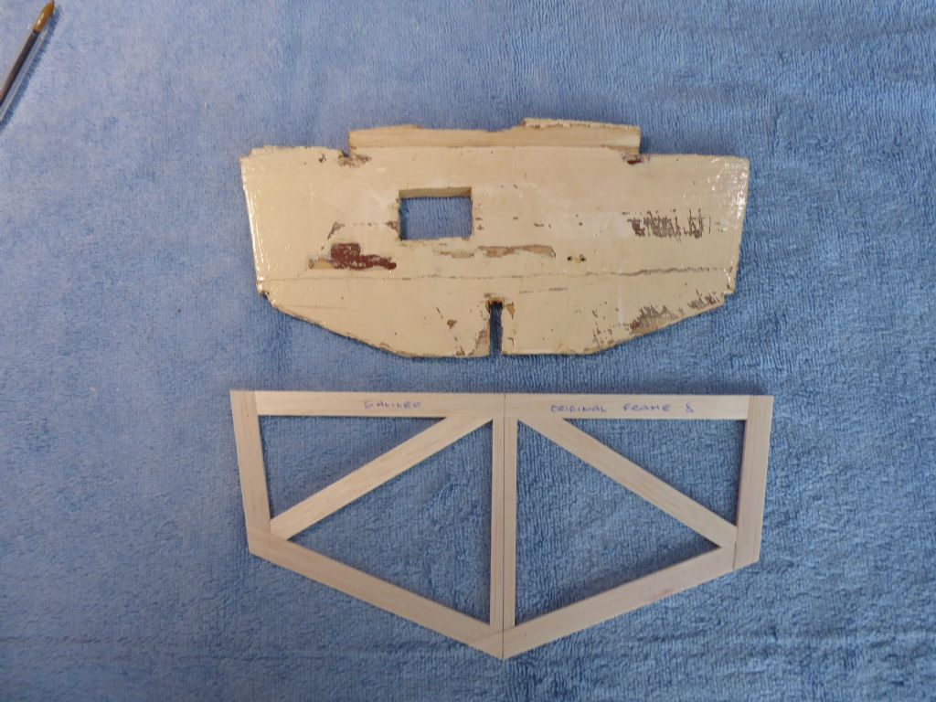
I mentioned saving the bulkheads. This is because I don't have the drawings anymore so it is a bit of reverse engineering. The new hull is surprisingly strong but I twists easily and the beam could be almost anything I wanted it to be.
Here is the old bulkhead number eight. Some bits are missing but there is still enough to use as a template remembering that there was 1/8" of balsa on the outside that I need to add to the new frame. Another feature of the original build was the lack of symmetry at some stations. The opportunity was taken to correct this with the new templates. I made templates of all the bulkheads I could save as a precaution, but not necessarily with the intention of using them all.
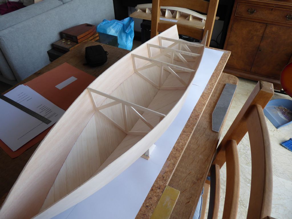
Here they are as temporary supports and mainly in the aft sections. This is because the forward part of the boat comes together as two conic sections and is rigid enough for the time being. The aft sections are much flatter and with the transom, really need the support. Here is where some of the original inaccuracies started to show and so it was a good opportunity to halve up the errors. I think the largest deviation from side to side is less than 3mm so perfectly acceptable.
While the two boats were together I marked in the sheerline and roughly trimmed the deck edge leaving a bit to spare just in case.
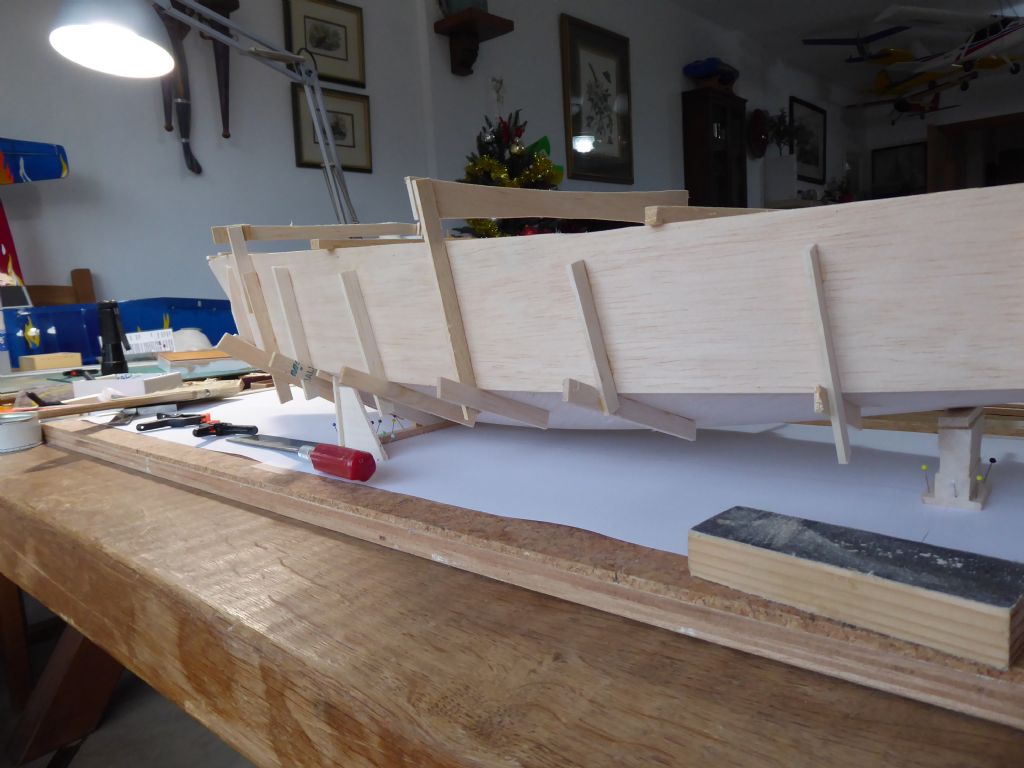
I am not a great fan of bulkheads unless they are strictly necessary and in fact this boat will have none. The templates are therefore purely temporary. In order to maintain the shape until it was stable I gave the hull some external framing.
These were only fitted at the chine and some were braced at a high level so at some point I would have completely clear access to the hull for glassing and fitting of the internal structures. The temporary frames were fixed with tiny spots of glue and were a softer grade balsa than the hull. This meant they could be snapped off easily leaving the small glue spots to be sanded off later during the general fairing process.
Tim
8 January 2019 at 22:01 #80598Tim Rowe
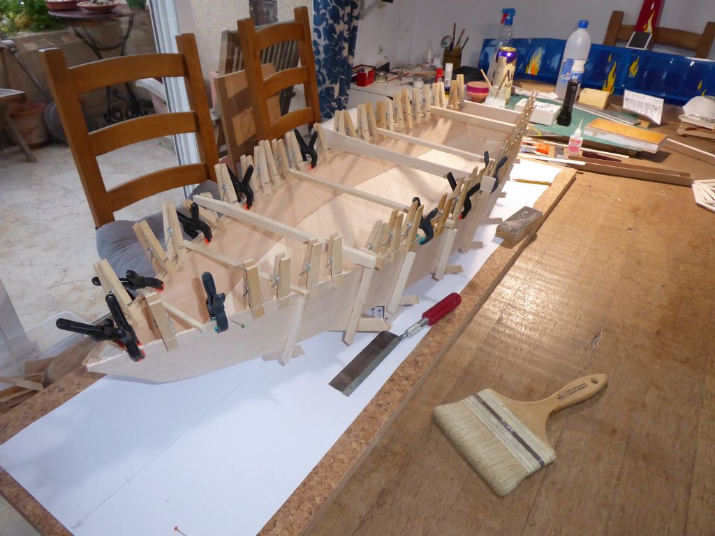
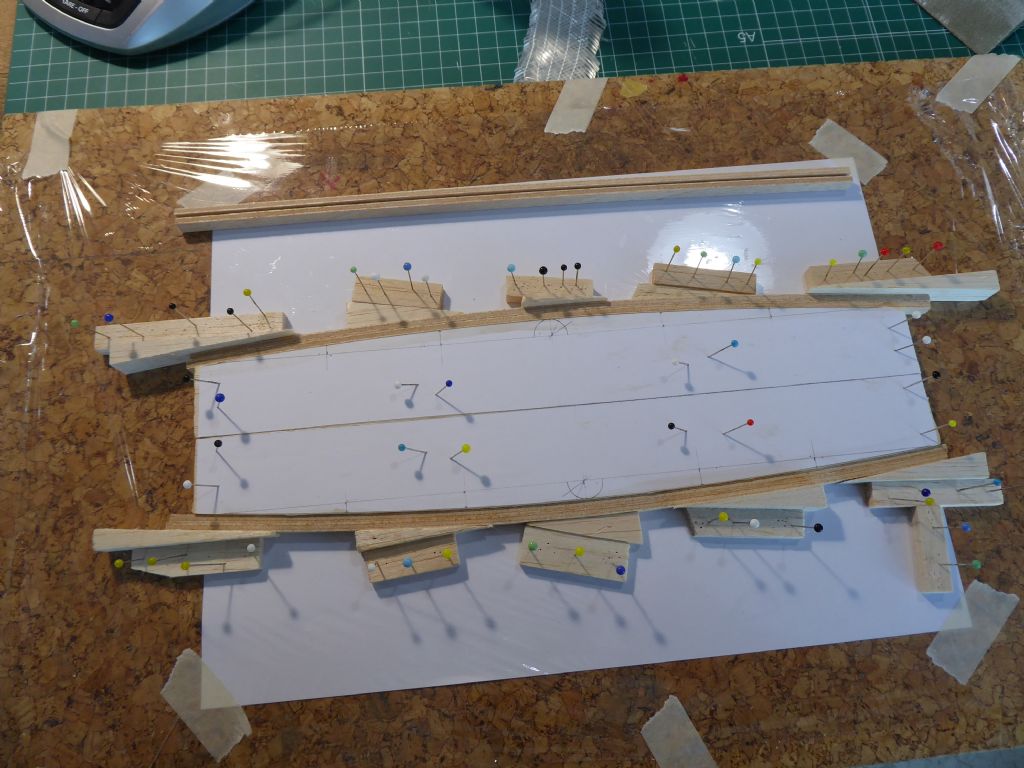
Participant@timrowe83142Confirming Ray's observation about the large number of pegs, here they are being used to clamp the inwhale in place while the glue sets.
Yes there are lots of them. I refuse to have the plastic ones in the flat so every time we buy some wooden pegs a few find their way to my toolbox. Hugely useful.
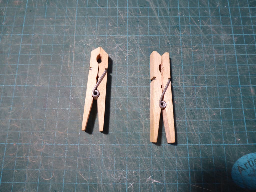
The pegs get instantly modified so I can which ones are mine
 and cutting the ends into points as shown on the left makes them incredibly more useful especially getting into tight corners. Furthermore, depending on which shop they were bought from they either have very strong springs or quite light ones. I keep them separate as the light ones are useful where only a small force is needed and the stronger ones would probably crush the wood.
 Tim
9 January 2019 at 00:32 #80602 Chris FellowsParticipant@chrisfellows72943
Looking good Tim and some nice carpentry there.
Pity it was damaged but it's giving you the opportunity to make a better job of it with your experience gained over the years and being able to incorporate improvements with regards to the construction etc.
I don't think the full sized boat looks as ugly as sin unless it looked worse in the "flesh"?
Chris
9 January 2019 at 11:00 #80606Tim Rowe
Participant@timrowe83142Thanks Chris. It is beginning to grow on me again as despite being hard chine it is quite curvy with a compound sheerline.
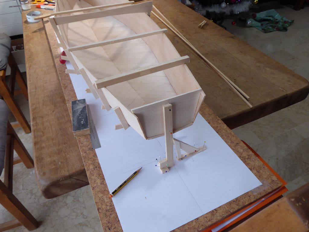
The last few photos show the model on a board. I am very keen on using jigs and templates wherever I can. It is not always convenient to have the model fixed on a base especially when it comes to fairing in lines which has to be done by eye.
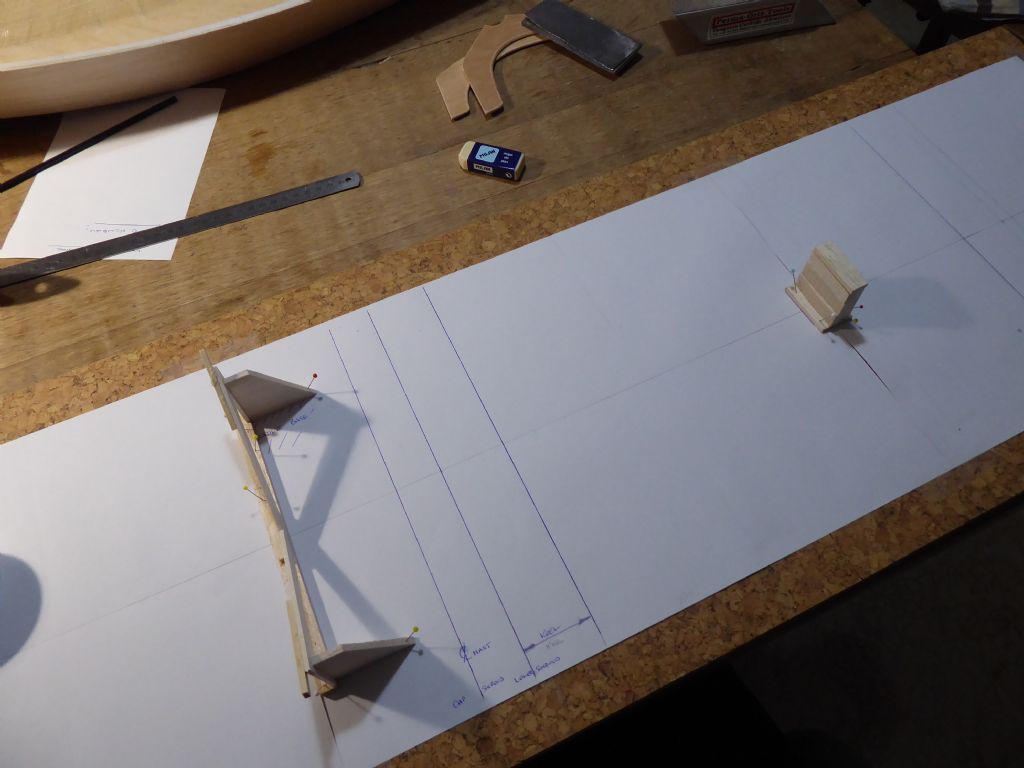
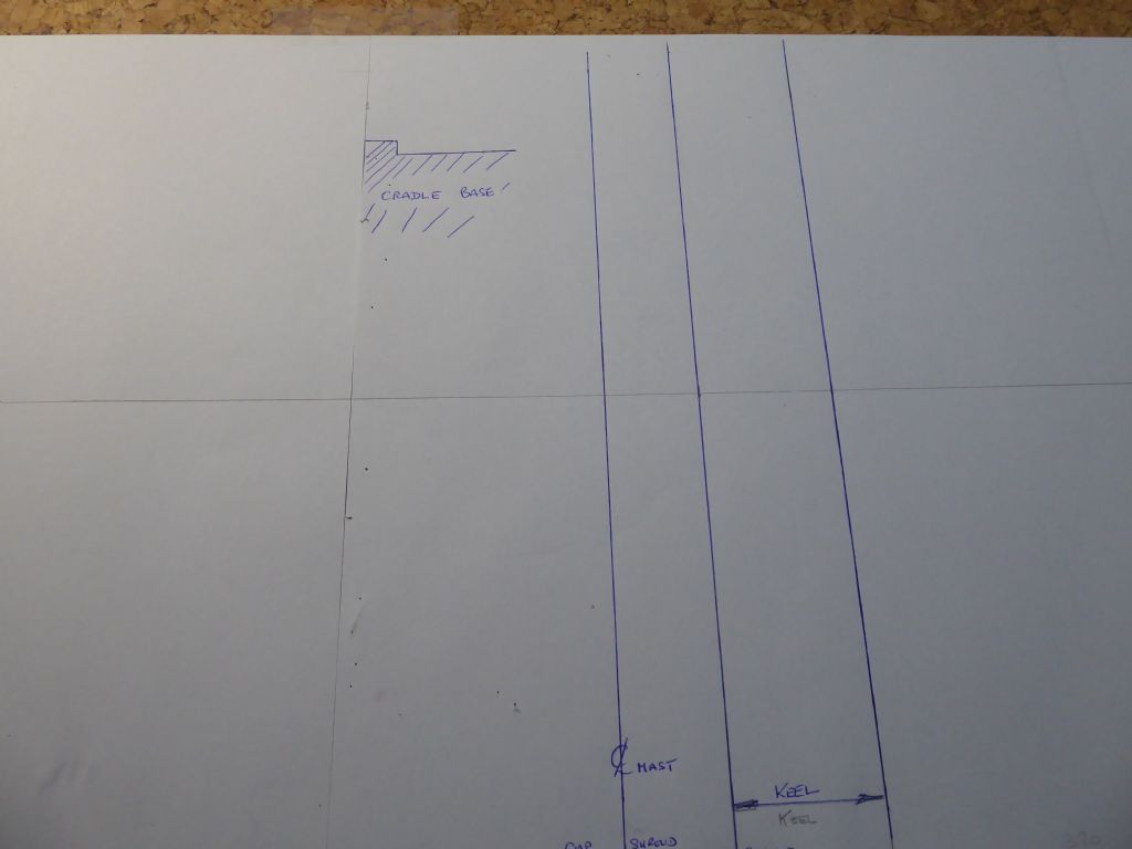
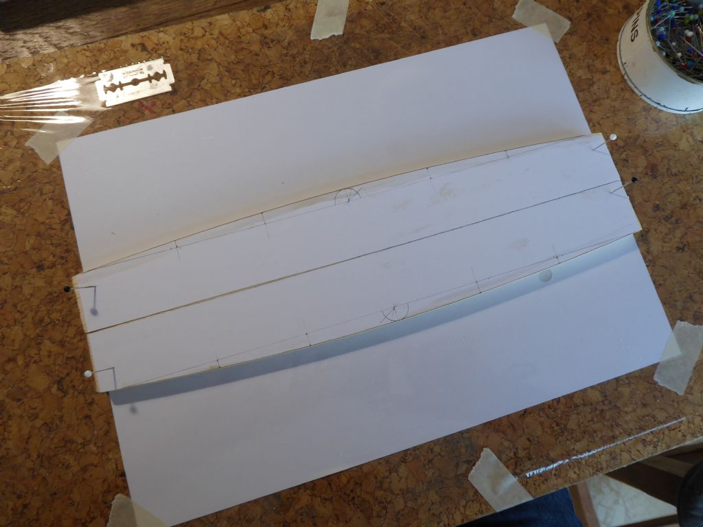
The board itself is my SLEC building jig on one side and cork tile faced on the side I am using now. Two and a bit sheets of A3 paper are taped down and a centerline drawn on the paper parallel to the edge of the board. Centrelines are very important and very useful. I took the shape of the hull in the mast area just forward of the keel and made a cradle. This is very nearly the widest part of the boat and makes the best reference even if the other stations are slightly out. The mast, keel and deck all have to relate to each other as accurately as possible. Further aft there is a simple block supporting the centerline so effectively the hull is supported at three points which is stable. The single block was positioned so that when the yacht is on the board it is on its designed waterline.
A line was then drawn at the position of the extreme bow so that the boat could be put back in exactly the same place each time using a square at the bow station. The transom has a centerline marked and this is lined up with the centerline on the board. Much easier to do than to describe.
The final stage was to draw around the bases of the cradle and block and show which way round they go in case I want to take them off at any time.The old deck was then used as a guide to mark the position of the mast and chainplates and I calculated where the new keel should go trying to maintain the same centre of lateral resistance. I seem to remember that the original model was quite well balanced except at extreme angle of heel.
Here the deck is being used as the guide.
And here are some typical reference markings on the building board.
It now only takes a few seconds to get the model accurately orientated and to transfer references.
Tim
11 January 2019 at 15:45 #80625Tim Rowe
Participant@timrowe83142The new hull was starting to get more rigid with the addition of the transom but was still a bit susceptible to twisting.
To fix this a centerline was marked on the transom to be lined up with the centerline on the building board.The hull was temporarily fixed to the cradle with tiny spots of glue and the transom lined up on the centerline. The little bit of twist was taken out with the brace you see in the photo. The hull shape is now effectively fixed.
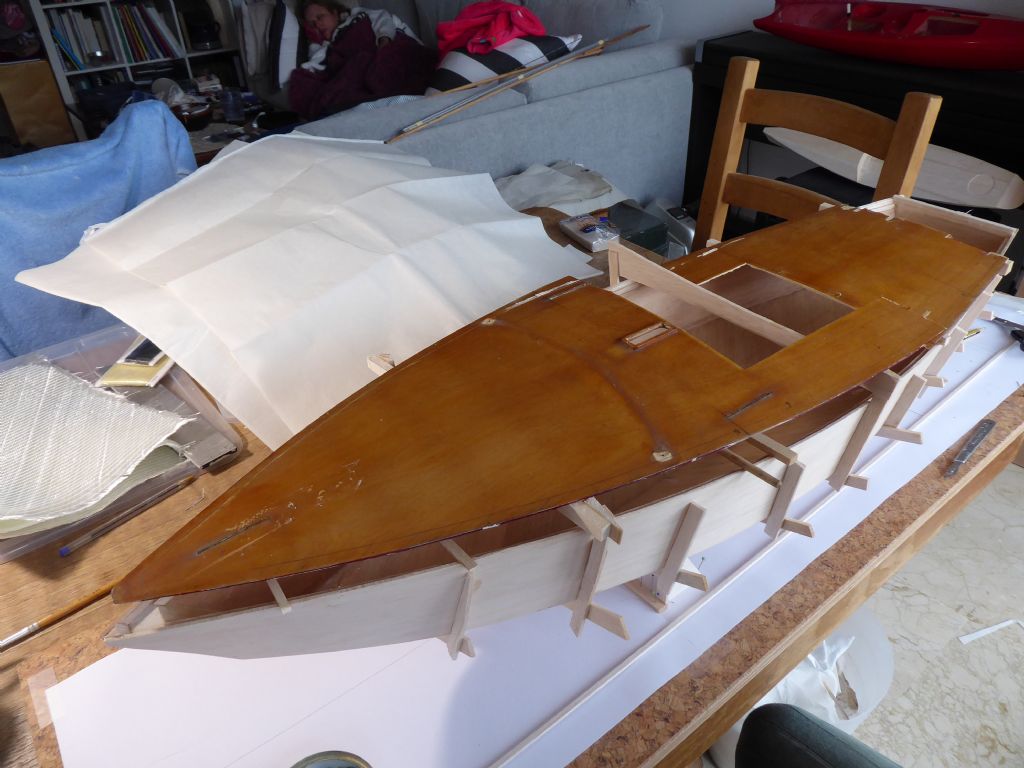
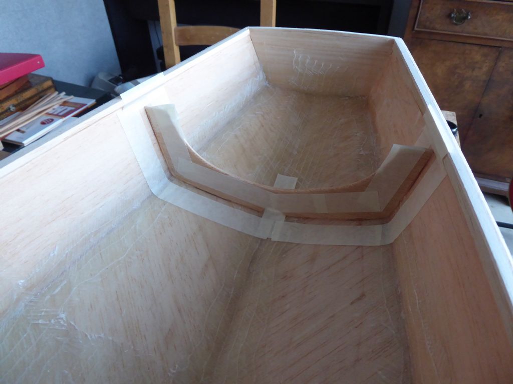
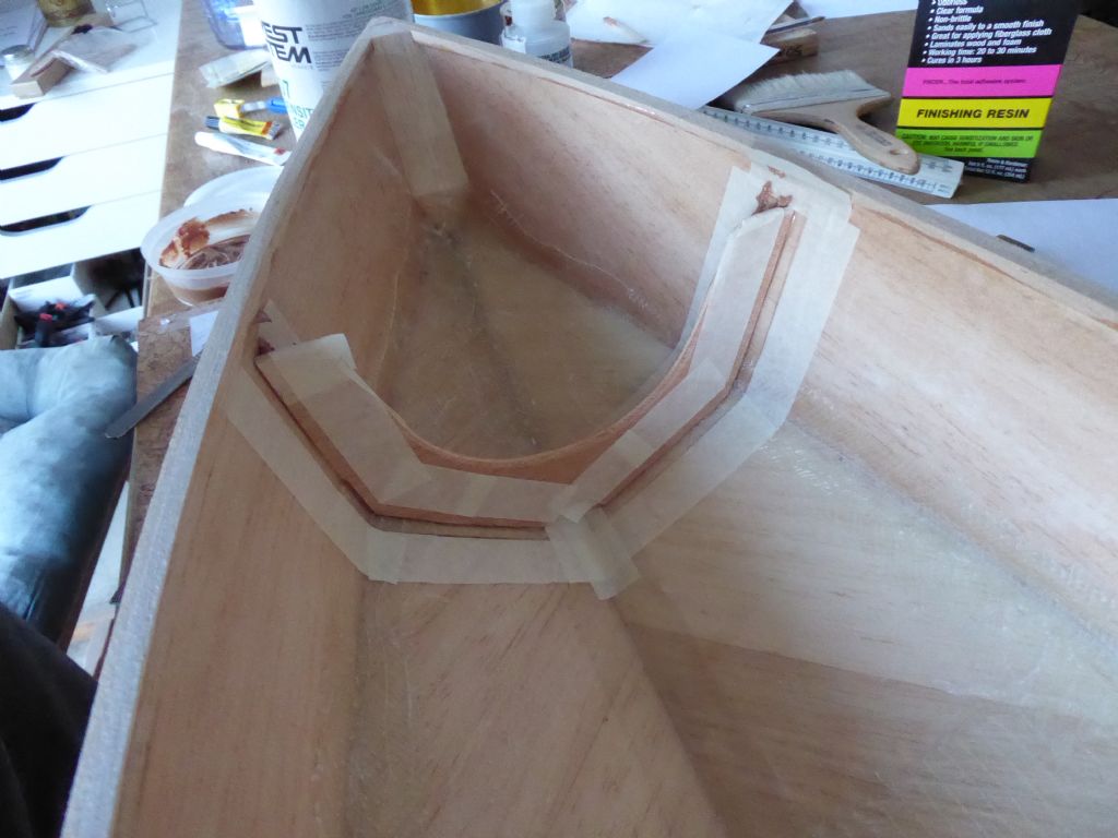
Next job was to line the entire inside of the boat. This was done with heavyweight paper tissue and low viscosity epoxy. This is much easier to do without bulkheads and provides quite a durable surface. Once built the inside should not be getting any knocks so there is no need to go overboard. The V of the hull and the chines were reinforced with glass tape and the centre section of the lower hull was reinforced with some bi-axial overlapped across the centre and up the side. This is where the keel and rig loads will be concentrated.
The reinforcing can be seen in this photo along with a lite-ply frame ready for fixing in the aft sections.
And another one forward. These were mainly to keep the ends in shape because they are outside the heavily reinforced area. Once the deck is on they won't have a great deal to do.
The frames were tacked in place with 5 minute epoxy and then fixed with an epoxy paste made from resin and micro-balloons. The tape is to keep nice neat edges to the fillets and is peeled off as soon as the resin starts to gel. Once this stage had set, the hull was sufficiently rigid in all planes and starting to get quite boat-like.
Tim R
11 January 2019 at 16:37 #80627 Ray Wood 3Participant@raywood3
Hi Tim
That is a precision job your doing !! taping the internal fillets, now that takes dedication and nobody gets to see them

I guess you have all the year round sailing out there, I'm envious, keep up the good work

Regards Ray
11 January 2019 at 20:29 #80630Tim Rowe
Participant@timrowe83142Hi Ray
No bulkheads in this boat so they could be on view and besides which I didn't foresee the inside of the original being seen again 50 years later! Seriously it is how I like my models to be. I am the same with my aircraft.
Back to the build and there are always bits and pieces it is good to have ready in advance and perhaps while something else is setting. Deck beams are needed in lieu of any bulkheads. In this part the boat is a bit more conventional.
There is can be quite a variation in "standard" deck camber depending on the era, country and type of boats. Many yachts were built with a camber of 1/2" to the foot. So a boat 10' wide would have a rise of 5" in the middle. I tend to use this as a starting point and then go up or down (usually down) to suit my thoughts at the time. I am basically metric and the boat is 280mm wide. That would mean a camber of 12mm which seemed a bit much when I mocked it up. I decided to reduce this to 10mm on the laminating former as the spring-back would reduce it still. I have ended up with about 8mm and I am happy with that.These are the formers pinned back to back on a spare building board. Two can be done at once.
They were all laminated at the same length with 20mm "trimming" on the longest beams. This is because it is impossible to maintain the fair curve right out to the ends of the laminates.Here are the basic deck beams laminated out of 20 layers of 3mm Liteply. The glue is aliphatic (my favourite) and the laminates are clamped as shown in the photo using balsa blocks pinned to the board and balsa wedges. The wedges are quite soft balsa and so compress and give a really good clamping action. I have loads of these blocks and wedges cut from scraps whenever the old ones wear out or get too full of holes. Later I added a third 1mm laminate of mahogany on the underside of the beams. This looks really nice and tightens the structures significantly with hardly any weight penalty. Any weight I can save in the hull, deck and rig can be added to the ballast keel where it will be more useful.
There are 11 beams and I have one spare. A quite satisfying job.
Tim R
11 January 2019 at 21:25 #80632 Ray Wood 3Participant@raywood3
Hi Tim,
Great work, I think the aero modelling accuracy is the key, currently working on a Comanche 32 cruising cat 1978 from blue Styrofoam which is so light it should float at the right waterline with ballast fin keels , time will tell ☺ have you many cats in Majorca ? My mate has the full-size moulds in his boatyard down the road in Allington. And I have a set of the drawings ☺
Regards Ray
12 January 2019 at 13:37 #80639Tim Rowe
Participant@timrowe83142Hello Ray
There are quite a few cats on the island and in the Balearics. Mostly they are day charter yachts. There are also the "booze cruise" catamarans for the youngsters who come here to get trashed every summer and more. You may have seen some of the excesses on the news.
I have never been a multihull fan although I do admire the extreme performance they are able to achieve like the first to sail around the world in less than 80 days Jules Verne style. I am not quite sure why but for sure when I am surveying a mono-hull, job done in one. When I am surveying a catamaran I do one, then have to do it all over again plus the bit in the middle

Looking forward to seeing some photos anyway.
Tim R
12 January 2019 at 18:33 #80642 Ray Wood 3Participant@raywood3
Hi Tim,
I've never sailed a cat but we have a dozen or so at my sailing club at Pevensey Bay Sussex, Hobbi 's & Darts, they go well in a straight line not so easy going round the corners 😀 I'm only doing the cruising cat as I don't believe anybody has produced a plan of a proper scale design, but I could be wrong at 1/12 scale is 32" long should be interesting 😃
Regards Ray
12 January 2019 at 22:58 #80650Tim Rowe
Participant@timrowe83142Hello Ray
Will be interesting to see how the model cat sails. Are you going to put a float at the top of the mast?
Another fill-in job on Galileo is to make the rudder. Here I have deviated completely from scale. My first rudder was scale and also had a skeg. It was totally useless and immediately I had to make a new one which was twice the depth but not very well supported. Needless to say it has not survived having got knocked off ages ago.
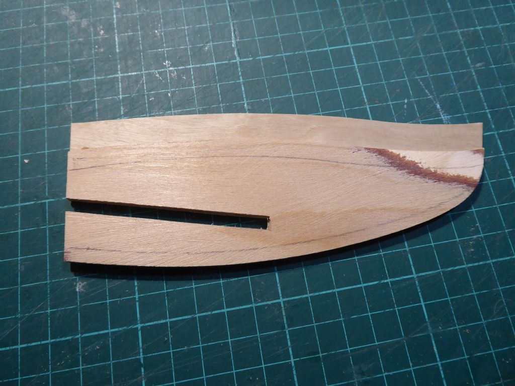
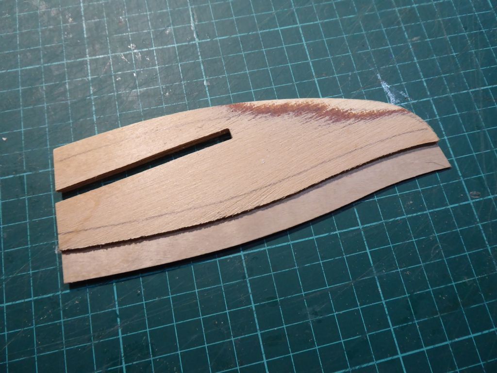
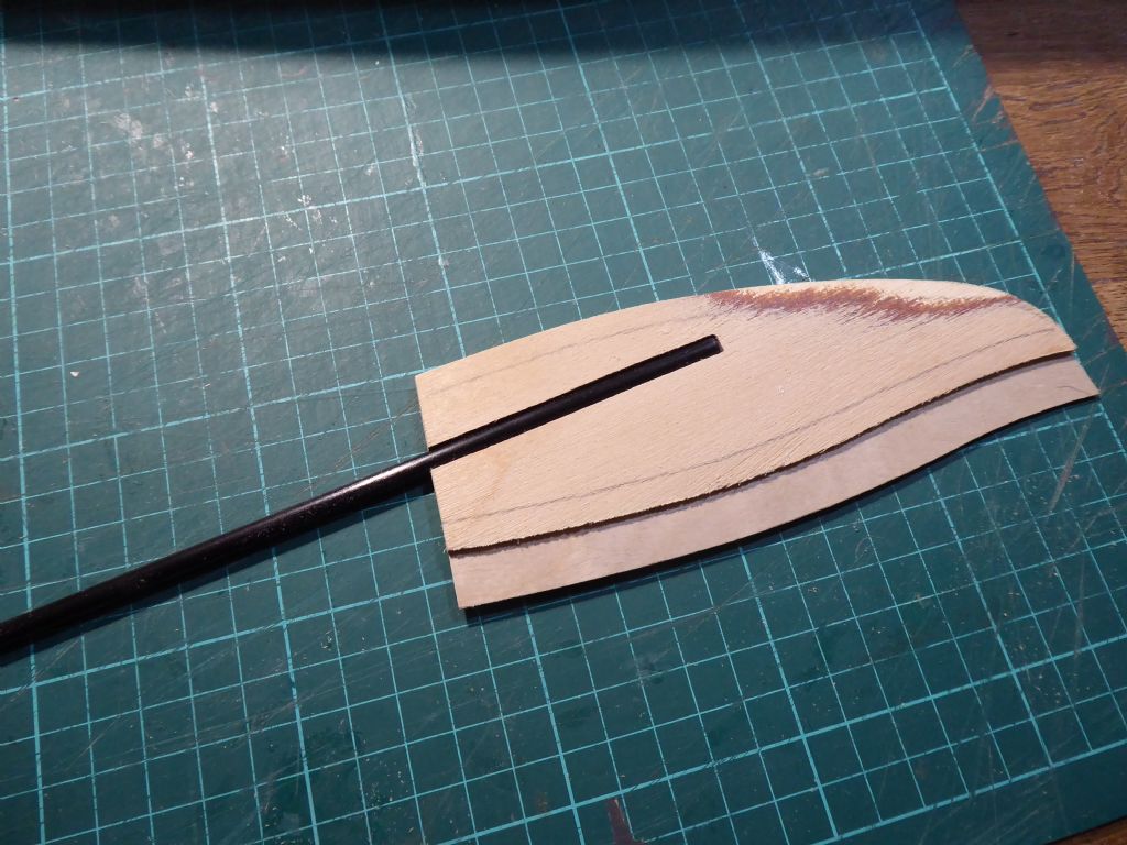
Here is the start of the new rudder. The construction is a centre laminate of 0.8mm ply with two side cheeks of 2mm ply. The cheeks follow the profile at the leading edge but are stepped back about 10mm at the trailing edge. This gives the start of an aerofoil section. The pencil lines are sanding guides to improve the section. The sanded area at the tip was to take out a little bit of unwanted twist I managed to get while laminating.
This is the other side and the step shows up much better. The sanded area was again to take out the twist.
The rudder stock is a length of 5mm carbon tube. Light and very strong. Here it is tacked in place with a couple of drops of cyano ready to be glued in permanently with epoxy and micro-balloons that was used to fill and fair the rudder fin. With a decent length of engagement, there is no need to have any mechanical connection from the stock to the plywood as there is a massive gluing area.
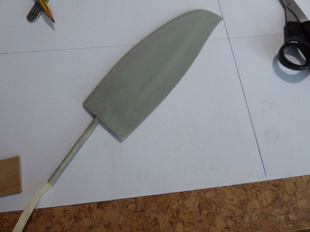
Here the rudder is in a high build primer. When sanding and profiling, the centre 0.8mm ply acts as a useful guide and as soon as it starts to appear you know you have arrived.
The priming is still in process with multiple coats and sandings until a completely uniform surface is obtained. The top coats will go on later when I paint the hull.
Tim R
13 January 2019 at 09:44 #80651 Ray Wood 3Participant@raywood3
Hi Tim
Yes the original sail plan shows a circular float on the masthead, i 'm sure somebody has turned one over in the past with to much sail up for the conditions! The design is relatively narrow beamed compared to current day cats, the existing moulds have been used to produce a wider version, which gives much more space in the centre saloon area, I would have been tempted in using the moulds, but I expect the resin & glass would cost £30 k now 😮I
Regards Ray
I like the carbon for rudder stock, will give that a go 😁
Edited By Ray Wood 2 on 13/01/2019 09:47:03
-
AuthorPosts
- Please log in to reply to this topic. Registering is free and easy using the links on the menu at the top of this page.
Code of conduct | Forum Help/FAQs
Latest Replies
Home › Forums › Sailing Models › Topics
-
- Topic
- Voices
- Posts
- Last Post
-
-
The new journey begins
1
2
3
Started by:
 mick east
in: Build Blogs
- 9
- 52
-
23 hours, 30 minutes ago
 mick east
-
New Website Forum – Discussion Topic
1
2
…
7
8
Started by:
 Colin Bishop
in: News and Feedback
- 20
- 183
-
1 day, 5 hours ago
 Colin Bishop
-
Tin Plate Clyde Puffer
1
2
…
7
8
Started by:
Len Morris 2 in: Scratch build
- 12
- 177
-
1 day, 6 hours ago
 Richard Simpson
-
Puffer advice
Started by:
 Alasdair Allan
in: All things floating
- 4
- 20
-
1 day, 8 hours ago
Len Morris 2
-
Todays Boating
1
2
…
200
201
Started by:
 ashley needham
in: All things floating
- 83
- 5,002
-
1 day, 17 hours ago
 ashley needham
-
Kempton steam open days incl boats
Started by:
 ashley needham
in: All things floating
- 2
- 7
-
1 day, 17 hours ago
 ashley needham
-
Purchasing Kits.
Started by:
Michael Cole 8 in: Building Kits
- 6
- 15
-
2 days, 15 hours ago
 ashley needham
-
Kempton Park Steam Engines
Started by:
 Colin Bishop
in: Shows and Events
- 1
- 1
-
3 days, 2 hours ago
 Colin Bishop
-
another Clyde Puffer
1
2
Started by:
mmcp42 in: Scratch build
- 7
- 45
-
3 days, 4 hours ago
mmcp42
-
Wanderer III
Started by:
grich101 in: Scratch build
- 4
- 5
-
5 days, 14 hours ago
 Ray Wood 3
-
Two more of my old models gone
Started by:
Bob Wilson in: Static modelling
- 1
- 1
-
6 days, 1 hour ago
Bob Wilson
-
Two more of my old models gone
Started by:
Bob Wilson in: Static modelling
- 1
- 1
-
6 days, 1 hour ago
Bob Wilson
-
May 2024 issue not in the archive?
Started by:
mmcp42 in: News and Feedback
- 2
- 5
-
1 week, 2 days ago
mmcp42
-
My Clyde Puffer
1
2
…
9
10
Started by:
James Hill 5 in: Scratch build
- 17
- 241
-
1 week, 3 days ago
Len Morris 2
-
Wild Duck meets Eventide
1
2
Started by:
Tim Rowe in: Scratch build
- 5
- 30
-
1 week, 4 days ago
 Tim Rowe 1
-
Ben Ain
1
2
3
4
Started by:
 Richard Simpson
in: Steam powered models
- 8
- 99
-
1 week, 4 days ago
 Richard Simpson
-
getting the boat to pond
Started by:
 Alasdair Allan
in: All things floating
- 3
- 8
-
2 weeks, 1 day ago
 ashley needham
-
MFA Motors ceasing business
Started by:
 Colin Bishop
in: All things floating
- 3
- 3
-
2 weeks, 5 days ago
 ashley needham
-
HMS Glory
Started by:
 Colin Miller
in: Build Blogs
- 4
- 18
-
2 weeks, 6 days ago
 Colin Miller
-
ss Miltiades 1901
Started by:
 Colin Bishop
in: Scratch build
- 2
- 3
-
3 weeks ago
 Colin Bishop
-
Amati j class yacht kit
Started by:
 ashley needham
in: Buy/Sell or Trade
- 4
- 6
-
3 weeks, 1 day ago
 ashley needham
-
North West Model Shipwrights Society
Started by:
Bob Wilson in: Club News
- 6
- 17
-
3 weeks, 3 days ago
Bob Wilson
-
ballasting a paddle steamer
Started by:
 Alasdair Allan
in: All things floating
- 5
- 17
-
4 weeks ago
 Colin Bishop
-
Aerokits pt boat bulkhead plans wanted
Started by:
Roo Hawkins 1 in: All things floating
- 1
- 1
-
4 weeks ago
Roo Hawkins 1
-
building a display case
Started by:
 Alasdair Allan
in: All things floating
- 5
- 17
-
1 month ago
 Colin Bishop
-
The new journey begins
1
2
3
-


