Billing Boats Smit Nederland

Advert

Billing Boats Smit Nederland

Home Forums Building Kits Billing Boats Smit Nederland

Viewing 12 posts - 26 through 37 (of 37 total)
  • Author
    Posts
  • #105552
    Richard Simpson
    Participant
      @richardsimpson88330

      How are you doing with the rudders George?

      Advert
      #105571
      gecon
      Participant
        @gecon

        Hi Richard,

        Rudders seem to be sorted now, but not installed. I was surprised to read on the label that Loctite was not waterproof. So the rudders spent 2 days in a bath of luke warm water.

        The only issue was that two aluminium toothed washers went a bit white and powdery on the surface. These were not involved in the Loctite job. They have now been removed from the assembly. These were added (and removed) by me…not supplied by Billing.

        I expect to be posting on progress next month. Buisy helping family members with home painting and decorating for the coming weeks.

        George

        #106082
        gecon
        Participant
          @gecon

          After a long lay-off, I'm dusting off the Smit Nederland components to try to work up some enthusiasm. Wife and I both got Covid 2 months ago. I was OK after a week but wife unfortunately seems to have a dose of 'long Covid'. Gradually getting better though -due to my supreme nursing skills no doubt.

          Had to dive into the archives to read up on DM's info' on elec' motor RFI suppressors. With 2.4G I probably don't need them, but other boats nearby might be effected. I have yet to experience 'another boat nearby' but decided to fit suppressors to this boat too.

          Having trouble soldering suppressor wires to the motor casing but note in the late DM's article that you can use a jubilee klip around the can to grip the end of suppressor wires. The motor can is such a huge heatsink that I suspect my 60W iron is not powerfull enough to generate sufficient local heat.

          Sticking out of the back of the motor at opposite sides of the outer rim are two small wires which look like ends of a fitted internal suppressor. These touch the outer can of the motor and maybe are there for me to solder on my suppressor wires?

          Anybody know?

          Off to buy 2 jubilee clips irrespective…..

          George

          #106083
          Tim Cooper
          Participant
            @timcooper90034

            George

            I have had the same problem with soldering the suppressor wires to the motor can. I rough up the area with Emery paper or a fine file then get some solder on before trying the tinned suppressor lead. I use a separate flux paste as well.

            Tim

            #106084
            gecon
            Participant
              @gecon

              I have managed to get a look in through the vents on the sides of the motors. The tiny wires at the edges of the motor can do in fact come from two small suppressors on the inside of the motor terminals. The other wire from the suppressor is wound loosely ( not soldered) around the motor terminal/tag on the outside of the backplate. I'll check that these outer casing wires have zero resistance across the motor casing and if so, will use them to solder on the other suppressors.

              This should work OK. If anything explodes, I'll mention it here next time!

              If you don't know what I'm talking about don't worry, neither do I.

              George

              Edited By gecon on 30/09/2023 10:29:25

              #106092
              gecon
              Participant
                @gecon

                Hi Tim, thanks for letting me know that 'it's not just me' smiley

                I have just (10 mins ago) looked in on Krickshop.de which is where all my brushed MAX 600 motors have come from.

                Written below the motor specs there is is a reference that "some of their motors are supplied with ready fitted INTERNAL supressors". "This can be identified by two small wires protruding from the casing at the motor terminals". All that is needed is a suppressor soldered across the motor terminals!

                I did mention earlier that I could see what looked like suppressors inside the vent slots. Nice to get it confirmed in black and white though.

                Alas! no need to get solder onto the motor casing! smiley I'll be soldering with confidence tomorrow.

                George

                #106095
                Chris Fellows
                Participant
                  @chrisfellows72943

                  Hi George, good to see you are making progress again.

                  I know exactly what you mean about building up some enthusiasm again. Having avoided Covid all this time I contracted it about 4 weeks ago when going with my mother to hospital. Didn't do anything for 3 weeks as I just couldn't be bothered! I obviously had the "man version" as my wife had milder symptoms and was over it in just over a week.

                  Just about over it though now and have started doing bits and pieces again.

                  Chris

                  #106096
                  gecon
                  Participant
                    @gecon

                    Hmmmm so you suggest that I had the 'girl version'!!female 

                    My wife and I believe that also WE got it when we took our daughter (50yrs! old) to hospital!  We had also avoided Covid "all this time".

                    So the safest action seems to be; don't go into hospital -unless you're the patient!

                    George

                    Edited By gecon on 02/10/2023 07:11:49

                    #106118
                    gecon
                    Participant
                      @gecon

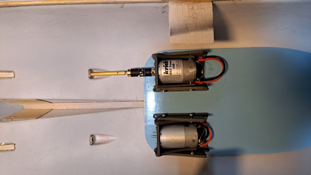
                      Not much to rave about, but due to all the previous posts about RF suppressors etc. here's a small 'offering' to show what the plan is.

                      Motors shown loosely placed on the equipment tray -which hopefully will end up being screwed to the keel in the bilges.

                      If I can get onto the new forum I expect to post a photo of the drive train in place and all the R/C on the tray in…xx weeks from now.yes

                      George

                      20231003_163156.jpg

                      20231003_164006.jpg

                      #112132
                      gecon
                      Participant
                        @gecon

                        ‘allo seilors!

                        I was very pleased to get a response to clicking on my ‘MB’ button this morning. Congratulations to all the crew who have been working on this task.

                        Time will tell how well my low cell-count, one-man-crew will tackle the rest.

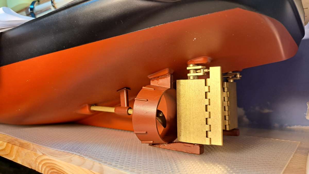
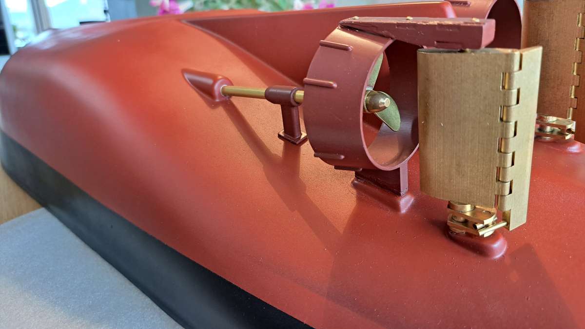
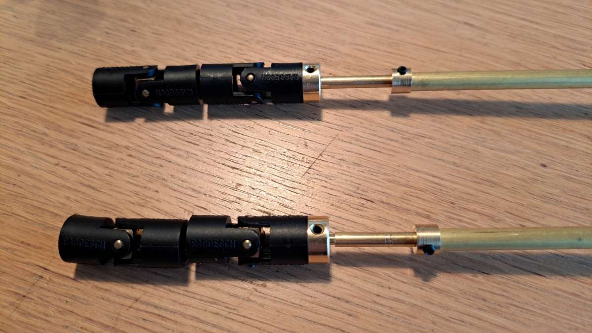
                        Work on the Smit-N has progressed at the usual snail pace. I’m still ‘under the hull’ trying to get the twin motor set-up installed. Been there for many hours in fact. The support bracket for the sterntube is a pre-formed plastic part. It’s position under the hull dictates the angle of dangle of the sterntube and therfore also whether or not the propeller ends up in the centre of the Kort nozzle. The position of the Kort nozzles is dictated by the physical connection to the base of the rudders. There are few variables but only very small corrections are needed to produce change in propshaft angle.

                        I’ve had each tube/shaft/prop unit in and out of the hull at least 10 times each and I’m still not fully happy with everything.

                        I’m getting there though, and hopefully by next week I’ll be able to connect the motors via u/v joints to the shafts.

                        Now, to try for a photo….

                        George

                        20231016_18243420231016_14365020231016_182454


                        #113978
                        gecon
                        Participant
                          @gecon

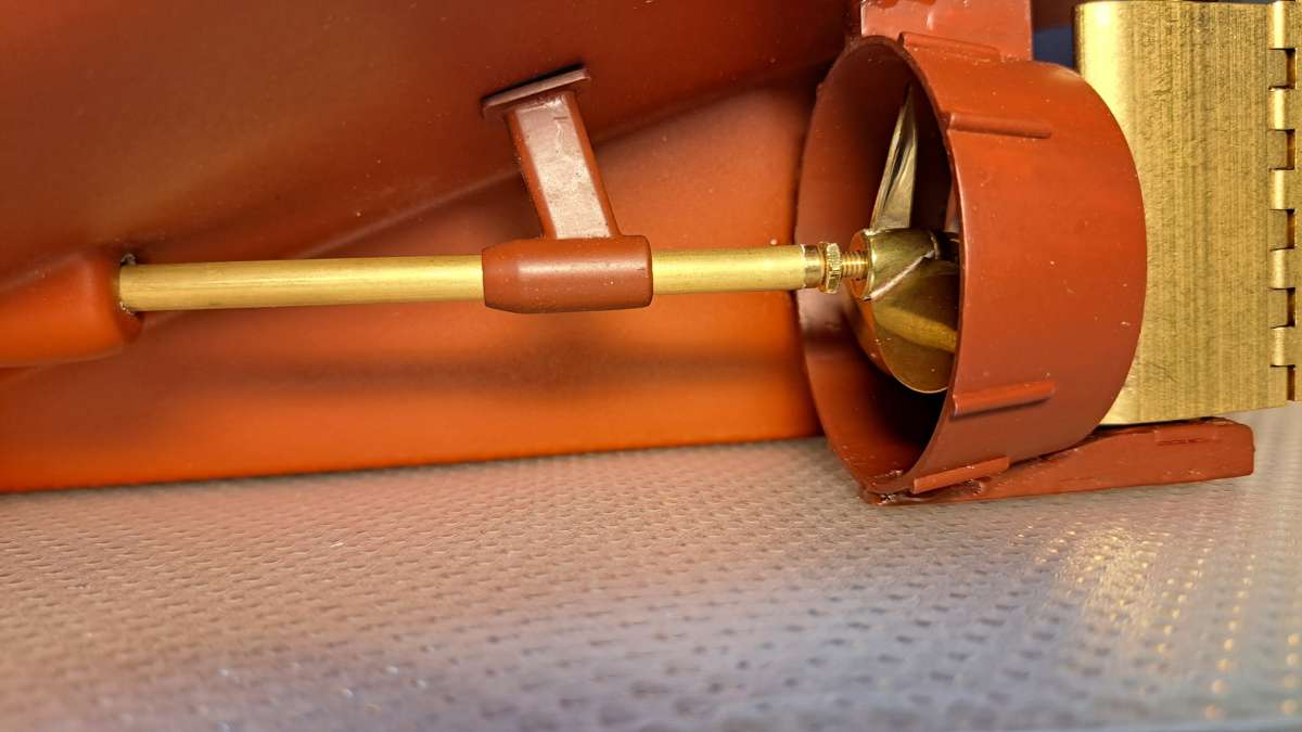
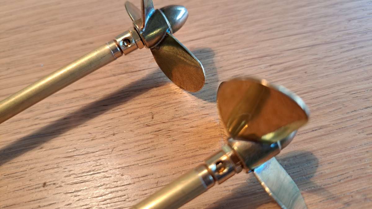
                          I’ve been trying to source two 4mm brass nuts here in Norway to no avail. I wanted to add locknuts to the propshafts. The photo above shows the single nut included in the kit to be used as a thrust-nut. The prop does not go any further onto the shaft than shown. I tried stainless steel M4 nuts but could not get them to thread onto the shafts, and they did not look right anyway. Don’t want to use Loctite as the props are diffcult to get at and would be almost impossible to unscrew again.

                          I found two 4mm brass rudder-shaft collets -which will have to do. They came with a 3mmX9mm bolt, so 3mm grubscrews have just been ordered.

                          I’ll be using double U/J’s. Splined joiners (converters) are also on order.

                          Have been doing several small planning jobs but nothing to show for it.

                          The upper prop and shaft assembly is actually the PORT driveline…sorry.

                          George

                          20231029_13100120231029_131036

                          #114774
                          David Marks 2
                          Participant
                            @davidmarks2

                            The nuts you require ar M4 half nuts. Whatever your source is for propshafts should be able to supply them as spare parts. They are a standard M4 thread which has a pitch of 0.7 mm.

                          Viewing 12 posts - 26 through 37 (of 37 total)
                          • Please log in to reply to this topic. Registering is free and easy using the links on the menu at the top of this page.

                          Code of conduct | Forum Help/FAQs

                          Advert

                          Latest Replies

                          Home Forums Building Kits Topics

                          Viewing 25 topics - 1 through 25 (of 25 total)
                          Viewing 25 topics - 1 through 25 (of 25 total)

                          View full reply list.

                          Advert