
Understanding plans

Understanding plans

Home Forums Scratch build Understanding plans

  • This topic is empty.
Viewing 13 posts - 1 through 13 (of 13 total)
  • Author
    Posts
  • #16072
    Peter Nordsjoe
    Participant
      @peternordsjoe33686

      Hello there,

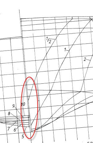
      I’m starting my first scratch build and am pouring over the plans, but there is something I do not understand which is what seems to be the empty space in the middle of the bulkhead drawings. As you can see the right side shows the foremost bulkheads and the left side the aftmost bulkheads. (I have cut most of the plans away for fear of copyright infringments). Any way, Down the centerline there is a gap and my question is why???

      http://www.modelboats.co.uk/wp-content/uploads/sites/5/images/member_albums/4011/bulkhead.jpg

      #16073
      Bob Abell 2
      Participant
        @bobabell2

        My guess is that the two parallel lines represent the spine or profile of the hull?

        Bob

        #16074
        neil hp
        Participant
          @neilhp

          I have always taken that"gap" to represent the thickness of the stem post, keel and sternpost.i.e. the backbone of the ship.

          if you are using a solid "backbone" including all three items mentioned above, it would be represented in a piece of timber such as ply, it would be the thickness of that "gap" on your plans.

          then if the "bulkheads" or "frames" as some call them are being fixed to the back bone they can be fixed in two ways.

          The first is to photocopy all your numbered frames at least once in one whole piece.

          I then, myself ,fold each piece of paper down that centre line and one  different frame is cut from each photocopy following the respective numbered line so that the 2nd half is cut at the same time giving total symitry. If you have 14 frames you end up with 14 cut out paper frames, all of different shapes. they can then be glued to the timber prior to cutting.

          Then they are attached to the backbone using a half housing joint. ie. half the slot is cut from the bottom end of each frame to the thicknes of the backbone, and the corresponding half slot ( the thickness of the frame) is cut from the top end of the backbone.

          If you go the other way and attach the "frames" to the backbone in two halves and not a whole frame, the "gap" represents the amount of frame that has to be taken off in order to give the true "beam" of the ship rather than an exagerated beam which you would get if you cut the frame straight down the centre line.

          Hope this is understandable.

          Neil.

          #16075
          Peter Nordsjoe
          Participant
            @peternordsjoe33686

            Hi Neil,

             Thanks, your comment was helpful. I still don’t get the empty space though. Why show the thickness of the stem post ect? I should want to use what ever thickness back bone I think appropriate for the build.

            I understood your description of folding the papper and getting identical sides. I was planning on using this approach. However, how do you compensate for the thickness of the planking? I’m planning on using 2mm ply.

             Regards, Pete

            #16077
            Paul T
            Participant
              @pault84577

              Hello Peter

              Both Bob and Neil are right in saying that the lines are representations of the keel or to be precise half the width of the keel for as Neil points out the drawings are intended to identical sides along a center line.

              The reason for showing the thickness of the keel is to give the builder correct instructions as the builder’s job is to build and not to have to make uninformed assumptions about the design.  

              If you wish to use 2mm ply for the planking then you will have to draw out the plans to scale and include the areas that are affected by the 2mm planking, at this point you have to make adjustments to the drawings to allow for the 2mm planking (but without changing the overall dimensions of the design) and then create a new set of templates. 

              Its not to difficult to do as long as you work all of you measurements from the center line, but if you get stuck drop me a line and I will help you sort it out.

              Paul

              #16081
              Peter Nordsjoe
              Participant
                @peternordsjoe33686

                OK Fat Controller. I think it is clear to me now.

                 Have a good weekend all!

                Pete

                #16150
                Peter Nordsjoe
                Participant
                  @peternordsjoe33686

                  Ok I*M STUCK!

                  I made the copies of the frames and folded them over to create a piece with two identical sides as previously instructed. Was quite fun and easy to do. Now the problem is to reduce by 2 mm all along the outer edge to compensate for the 2mm plywood skin.

                   The way I imagine it needs to be done is to measure 2mm in from the edge (at right angles from the edge), all along the edge and then connecting these dots to form the new line. But I am hoping some old hand has a trick to get around this rather tedious process?   

                  Help!

                  #16151
                  neil hp
                  Participant
                    @neilhp

                    sorry peter but ther is no real easy or quicker way to do it other than by using the "finger guage" method

                    that is to rest your pencil between thumb and fore finger so that it protrudes the required distance  , and in your case that would be 2mm and run it around the edge of thesubject, using the fore finger as the item which touches the material ti give the guage distance. giving  parallel line to the edge of the material….usually timber or card, where it works easily..but a little tricky with paper.neil.

                    #16152
                    Bob Abell 2
                    Participant
                      @bobabell2

                      Peter

                      You`re tying yourself into needless knots!!

                      Just follow the drawing…ie…Don`t change NOWT!….and just get with it!

                      Bob

                      #16153
                      Peter Nordsjoe
                      Participant
                        @peternordsjoe33686

                        Hehe okey. Yes sir!  Just glad to know I’m not overlooking some other brilliant way of doing it. One stiff drink (to steady the hand as it were) and off I’ll go!

                        #16155
                        Paul T
                        Participant
                          @pault84577

                          Peter

                          You could use a pair of dividers or a drawing compass…just set the 2mm and follow the outside line but Neils "finger" guage has always worked for me.

                          Paul

                          #16170
                          Peter Nordsjoe
                          Participant
                            @peternordsjoe33686

                              Bob was right. Piece of cake! Thanks all.

                            #6501
                            Peter Nordsjoe
                            Participant
                              @peternordsjoe33686

                              What is the empty space?

                            Viewing 13 posts - 1 through 13 (of 13 total)
                            • Please log in to reply to this topic. Registering is free and easy using the links on the menu at the top of this page.

                            Code of conduct | Forum Help/FAQs

                            Latest Replies

                            Home Forums Scratch build Topics

                            Viewing 25 topics - 1 through 25 (of 25 total)
                            Viewing 25 topics - 1 through 25 (of 25 total)

                            View full reply list.