
Landing Craft Front Ramp Lifting Gearbox

Landing Craft Front Ramp Lifting Gearbox

Home Forums All things floating Landing Craft Front Ramp Lifting Gearbox

  • This topic is empty.
Viewing 16 posts - 1 through 16 (of 16 total)
  • Author
    Posts
  • #30943
    Robert Walters
    Participant
      @robertwalters31200
      Hi all, I am buildind a Landing Craft and I am haveing trouble finding a gearbox with metal gears throughout for lifting the front ramp. The box I have been trying to use is the mfa 917D series but this isnt strong enough, I have been trying a slightly larger box, (which I purchased some time ago from alwayshobbies for a paddle boat which didnt materialise) but there is a heck of a strain on the winch and I’m afraid with there being plastic gearing the teeth tend to strip. Does any one of you gentlemen or ladies out there know where I may be able to purchase a gearbox with metal gears inside
      #3732
      Robert Walters
      Participant
        @robertwalters31200

        metal geared gearbox

        #30978
        ashley needham
        Participant
          @ashleyneedham69188
          Robert. How big is this landing craft door?? Must be a real whopper.
           
          Are you pulling it up on wires/string/whatever or levering it up from its hinge??
           
          Ashley
          #30982
          Dave Milbourn
          Participant
            @davemilbourn48782
            I think you have an old unit there. MFA/Como currently list the type 918D (280 motor) and the 919D (540 motor). Both types are fixed single ratio and have metal gears.
            Hope this helps.
            Dave M
            #30996
            B B
            Participant
              @bb42502
              If all else fails, try building your own gear box using metal gears which can be purchased at hobby shops who specialise on radio control cars. All types of gears are available and realatively cheap. I have used these gears for the working anchor winches.
              Bernhard
              #31038
              Kimosubby Shipyards
              Participant
                @kimosubbyshipyards
                Robert,
                I’ve built the Sea Crusader (Deans Celestine) and its ramp can be lowered from the vertical to horizontal and back again.

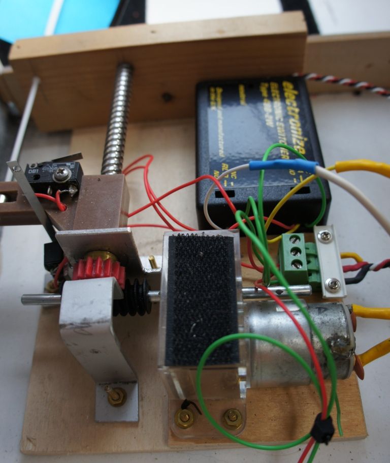
                The ramp mechanism is well inboard, the actual lifting/lowering is achieved with an aileron nylon cable which is attached to the ramp at one end and the other to a bar which travels along a worm thread (from a photocopier actually). The bar is brown coloured in the picture below.
                The worm travel is controlled by micro switches for max up or down positions. The motor direction is changed utilising a two way switcher and a Tx channel.
                The worm was turned using a geared motor about 68:1ratio motor from Squires with small yellow plastic gears. The one in the picture did burn out (I was using 6V and it was rated 4.5V) but it did last near 2 years.
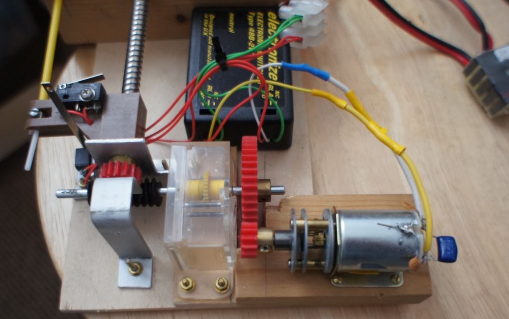
                The replacement drive is an MFA 918D151/1 (15:1) and it is 3V, so I had to put in a voltage reducer, again from MFA. This new unit is much faster (obviously), so it actually drives through two additional plastic gears to up the gear ratio, now about 35:1. Works extremely well.
                If you want a full plan and wiring used just “give me the nod”. The geared unit initially used was an educational gear box and motor as sold by Squires, where the gear ratio could be changed quite easily within the gearbox.
                Kimosubby


                #31067
                Robert Walters
                Participant
                  @robertwalters31200
                  Kimosubby, your setup looks great, a really proffesional job. I have posted a couple of photos of my model, as you can see from the gearbox photo I am stuck for space. I have discarded the gearbox shown and am trying an identical gearbox as the one you are showing in your photo, only I have fitted a mounting plate on the other end and turned it upside down because the through driven shaft is to high to go under the aft deck of my model with the rope drums fitted. (One thing about these problems they dont half keep the old brains working) I would like a copy of your plans and wireing please for future models. Your model of the “Sea Crusader” looks really smart. R WALTERS
                  #31088
                  Kimosubby Shipyards
                  Participant
                    @kimosubbyshipyards
                    Hi Robert,
                    slow getting back to you, I’ve been over to your Island for a quick trip!
                     
                    I’ll post here the new layout as now fitted and I’ll see how it can be compacted. On the Sea Crusader I have enough space for the kitchen sink, so didn’t have to design with space in mind.
                     
                    Looking at the setup you have shown, I assume you are trying to lift the ramp with both cables shown on each side of the bow, then having to have two drums to match up to do the lift/lower. On my set-up I have only one side lifting, the other is a dummy!
                    Also looking at your wiring, are you using a servo to engage micro switches to change the direction of motor rotation?
                    Is there a microswitch to stop the motor when the ramp is up? (If there is not, and with the gearing shown, you can easily strip the motor gear when the ramp is up but the motor would still be turning with no end point for it to read – just you at the water’s edge.)
                    Can I ask what weight is in the ramp? and whether the ramp is hinged along its whole length on the pivot points of the hull?
                    I also note the ramp remains angle when up, so how tight does this have to be in the up position for water integrity?
                    And lastly, what is the length of travel for the cable attachment point from full down to full up?
                     
                    My ramp hinge has a brass rod through tubes soldered to plates and fixed evenly along the joint so that the strain should be evened along the length, hence I can pull up or lower down on one side. On yours, to effect a dummy on one side you could use elastic thread inside the hull to keep the dummy tensioned, whilst only one cable doing the work – that would enable the drum to be on one side only.
                     
                    I’ll draw up the wiring too, I need to update it anyway as I now have the 3V motor and current reducer to add in.
                     
                    Give me a couple of days – its our annual open event this weekend, and I’m competing on Saturday in steering – then judging Sunday for the static displays of all classes.
                     
                    I’ll be in touch, Kimosubby


                    Edited By Kimosubby Shipyards on 21/06/2011 15:30:25

                    #31089
                    Robert Walters
                    Participant
                      @robertwalters31200
                      Hi Kimosaby,
                      The box I amuseing as you can see has the drum shaft running right through at right angles to the motor, a worm gear on the motor shaft driving the gear fixed to the drum shaft. I found it more even on my model to pull from both sides, its just a question of getting the ropes set up to pull evenly, the drums can be adjusted to set the ropes even.
                      The two miniture servos you can see are for the drive motors, not the ramp motor.
                      I dont know the weight of the ramp, and the tightness of the ramp to the edge of the hull has yet to be tested. The ramp will not be lowered whilst model is in the water, the lake we use at our club has an 18inch wall all around it so there is no “sandy beach which can be stormed”.The hinge is a piano type right across the front and the ramp will have to have elastic bands or light spring attached to help it down, this I have tried and it worked. The base of the ramp is, on the outside sealed with tape coated with a thin layer of resin The rope travel is 4inches, about 5 turns on the drum. As regards to the stop this has yet to be thought out, it may (probably will) finish up being a DPDT reversing switch withme standing over it.
                      OK thanks for your reply, Bob Walters
                      #31090
                      Dave Milbourn
                      Participant
                        @davemilbourn48782
                        Robert
                        This might help grease your thought processes:
                        Top drawing is probably the most relevant unless the motors are drawing >3A ( in which case go to the P93 drawing).
                        Dave M
                        #31091
                        Kimosubby Shipyards
                        Participant
                          @kimosubbyshipyards
                          Well Robert, here’s those promised bits, I’ll read your latest in depth and get back.
                           
                          The first thing to say is I am using a two way switcher complete with micro switches for the motor end points (ramp travel end points). Very much as per Dave’s link.
                           

                          There are two more very similar images in the Sea Crusader album. This is the new set-up with the smaller 3V motor etc as previously described.
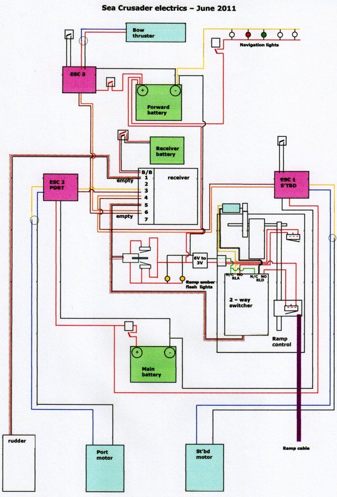
                          Below is the complete wiring diagram, you should be able to pull out the ramp mechanism details which are located right of middle and below.
                           
                          The gearing requires someone to assist please in the calculation.
                          The motor is geared 15:1
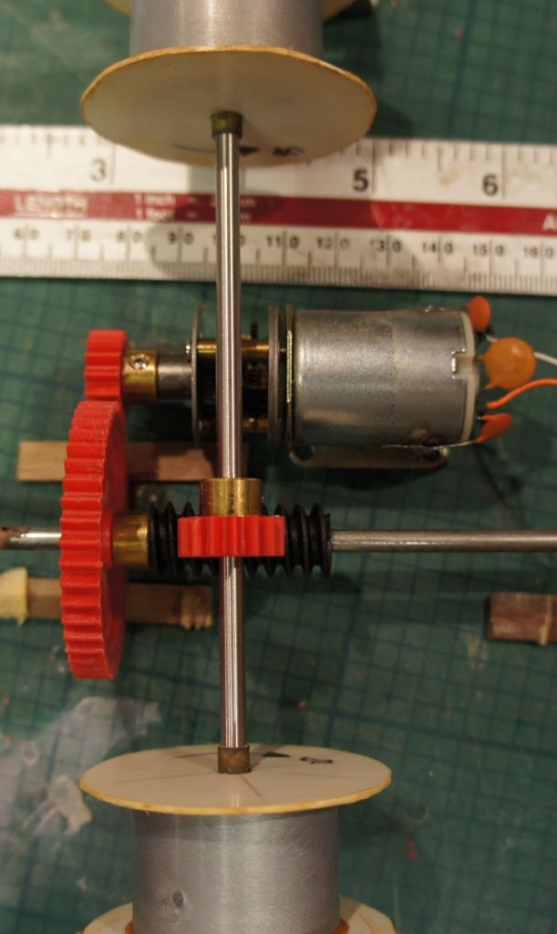
                          The drive gear from it to the large red gear – motor drive 12 teeth, large gear 45 teeth (45/12 = 3.75) added to motor gearing gives (15 x 3.75 = 56.25). Is this correct?
                          The large gear turns shaft to black worm gear (assume 1:1?) and the take off red gear from the black worm to the worm traveller shaft is 15 teeth ? does this alter the overall ratio?
                           

                          [Electrics June 2011 Sea Crusader .]

                          Any way Robert, as you can see there is plenty of scope to decrease overall size. The controlling physical factor is the worm drive shaft length, mine gives near 3″ travel which is enough for the ramp as built.
                          To increase this travel for your ramp I would introduce a pulley system so that the travel block on the worm is magnified by a factor of two. Instead of pulling in the cable direct, attach its end to thread and fix its free end to the end mounting. Use a pulley to pull the thread back so that you are pulling in two lengths of thread for one of worm length travelled. I’ll post a diagram of that for clarity.
                           
                          Hope some of this assists you.
                           
                          Kimosubby
                           
                          PS I do happen to have a short length of worm threaded stainless – came form a photocopier x,y mechanism.

                          Edited By Kimosubby Shipyards on 21/06/2011 19:36:48

                          Edited By Kimosubby Shipyards on 21/06/2011 19:49:49

                          #31107
                          Kimosubby Shipyards
                          Participant
                            @kimosubbyshipyards
                            Hello Robert,
                            I’ve read through your post and think the gear stripping must be associated with the end point on lifting the ramp. You don’t say which ones strip, but its either the motor end or the drum shaft ones by the look of your set-up. My ramp, which I had to re-make and reinforce with brass square section weighs in at nearly 2lb and is lifted from a pivot close to the hinge and a pull up travel of just over 2″. I’ve had no gear stripping, even using the thin plastic gears less than about 0.5mm thick.
                             
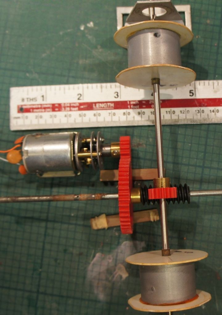
                            As you said, these problems get the grey matter going, and here’s my idea, for what its worth, for your ramp gear, it still depends on available space, and this is the smallest it can get with the gear suggested.
                             

                            There are options, I’ve shown two, both with take off shaft over drive. The layout is all balanced for the picture, shaft supports will be required.
                            NOTE: using a smaller “large” gear will reduce the height dimension quite a lot.
                             
                            The basic layout for the motor and take off gear wheels requires a 70 x 70 floor area, and a height of 50mm for the larger gear wheel to clear floor level. The cross shaft to the drums with its associated gear wheel are a maximum of 50mm above floor level, with, in these layouts, the centre of the cross shaft 35mm above floor level. I’ve shown two drums I had made from plastic car wheel drums which I was going to use for lifting lee boards on a thames barge, but I found a far simpler, quicker and easier method for that.
                             
                            The motor shown is the MFA/COMC metal geared 3V as in the Sea Crusader, the other gears are from SHG as is the shaft material and worm.
                             
                            Gearing shown is 15 to 45, motor drive to worm, and from worm another 15 toothed cog. So overall gearing is 15:1 (motor) plus 3:1 drive cogs plus 15:1 worm gear (as one revolution of the worm rotates shaft gear one tooth); thats 675:1. There’s also the drum diameter to factor in? That should lift the ramp ( and prevent any unwind due to ramp weight.
                             
                            Just a suggestion. I think you still require something to break the electric supply as the ramp reaches the up/down position – there’s always some over run when the motor is stopped. I once pulled in the sides of a barge with a similar set up, I’d believed I needed wire to lift the boards, so it acted like cheese wire (I also neglected to instal a fuse as the ultimate fail safe)!!! The motor just kept turning and pulling in. I as the weak link!!!
                             
                            Kimosubby.
                            #31120
                            Mark Beard 1
                            Participant
                              @markbeard1
                              If you use micro switches as limit switches to cut power to the motor, don’t forget a reverse biased diode across each switch to save the contacts from arcing when it opens.
                               
                              #31129
                              Kimosubby Shipyards
                              Participant
                                @kimosubbyshipyards
                                Hi Mark,
                                 
                                I’m assuming that the two way switcher I use has these already built in (the circuit diagram shows 3 on the board) and the instructions do not indicate their use.
                                 
                                I confess to knowing little of the science of electronics – how does putting the diodes in the circuit work to reduce arcing – and secondly, should the micro switch be on the positive as I have shown, or the negative? Again is there a reason?
                                 
                                I note the Action Electronics circuit always has the micro switches on the negative feed.
                                 
                                To date, I have not had any problems indicated.
                                 
                                Kimosubby.

                                Edited By Kimosubby Shipyards on 23/06/2011 18:21:43

                                #31151
                                Mark Beard 1
                                Participant
                                  @markbeard1
                                  Kimosubby, I’m struggling to find the Action Electronics product you’re using on their website, but from your wiring diagram it looks like it has two SPDT relays. If that’s so, two of the on-board diodes will be for protecting the transistors used to drive the relay coils and the third is probably used in the power supply circuit.
                                   
                                  When you turn off a device containing a coil, including a motor, it generates a very brief high voltage spike. (The RFI capacitors fitted to motors are to reduce radio transmission from these spikes as the motor commutates). This can damage switch- and relay-contacts.
                                   
                                  To protect both your micro-switches and relays on the switch board, I recommend connecting two small diodes, each between the negative supply at the n.c. contacts and the common contacts connected to the motor. The cathode (the end with the stripe) of each diode should be connected to the common contact to the motor. Suitable diodes for this are 1N4001 which are available from Maplin, part number QL73Q at £0.24 each.
                                   
                                  Of course, if in doubt please check this out with Action Electronics. Since I can’t find a twin relay board on their website, they may have some kind of protection on the board you have in addition to the relay contacts. But I note that with other switch boards they do recommend such diodes are added externally.

                                  Edited By Mark Beard on 25/06/2011 11:22:48

                                  #31152
                                  Mark Beard 1
                                  Participant
                                    @markbeard1

                                    The way diodes help arcing is that the coil momentarily ‘tries’ to keep the current flowing when your switch tries to stop it. The coil does this by producing enough voltage to maintain the current, and if that means producing a high enough voltage to create an arc across the contacts, then so be it! The diode provides a simple bypass pathway for the current, which needs less than 1Volt to sustain it. 1Volt is not enough to create an arc, so the contacts are protected.

                                    It makes no difference to function whether you put the switches in the positive or negative feed, but for the diodes to work as I’ve described, the positive feed is ideal.
                                    Glad you have not had problems to date, and truth be told you may never have. But the arc could be causing a tiny amount of burning each time you switch off the ramp motor and one day may either fail to switch on – or weld closed and fail to turn off!
                                  Viewing 16 posts - 1 through 16 (of 16 total)
                                  • Please log in to reply to this topic. Registering is free and easy using the links on the menu at the top of this page.

                                  Code of conduct | Forum Help/FAQs

                                  Latest Replies

                                  Home Forums All things floating Topics

                                  Viewing 25 topics - 1 through 25 (of 25 total)
                                  Viewing 25 topics - 1 through 25 (of 25 total)

                                  View full reply list.