
The world's leading magazine for all model boating interests
Home › Forums › Scratch build › Shemarah II
I'm glad you like it Larry. It does sail really well and I am now hopefull that it will be finished by this summer and will get a few outings to the local shows and regattas. I have already started planning the next project and I'm keen to start cutting some major bits of plywood again, although I also have to make a box for Shemarah first.
I hope you are well on the way to recovery after your recent operation and will soon be able to be trusted to wield a Stanley knife again.
Regards
Gareth
Good Morning Gareth,
Getting better slowly , craft knife at the ready , to do a bit carving a Nessy,
orders of the grand kids,
such a good item to get them at pool,
any chance to show power set , and wiring digram ………….cheers Larry ………
Hi Larry,
I will put a wiring diagram and a few photos on the Nessie thread, maybe later tonight, maybe tomorrow.
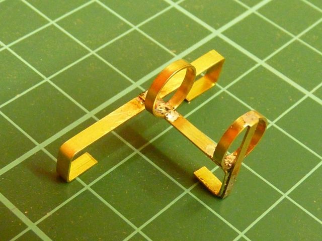
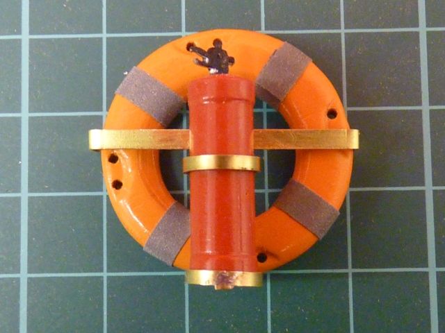
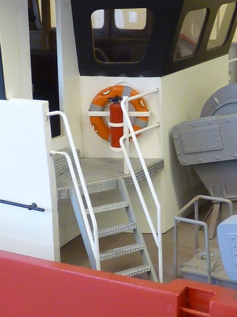
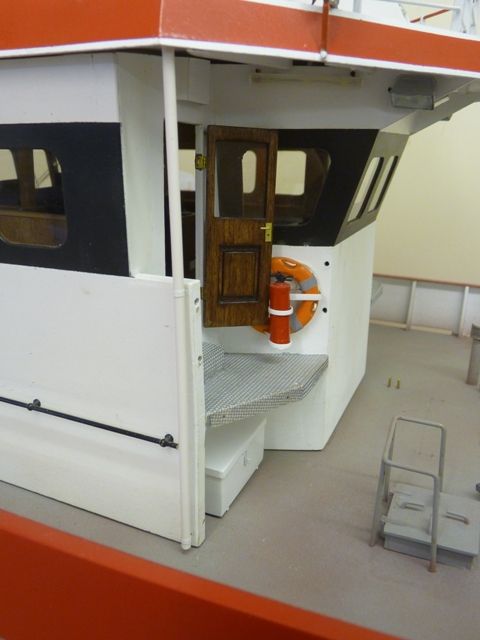
The last few days have seen a bit more progress with Shemarah's wheel house. I made up the brackets that support the lifebelts and fire extinguishers using 1/64" thick brass strip soldered together.
The li
The lifebelts were home made some time ago but I cheated with the fire extinguishers. They are from Battlecrafts and came ready painted, although they will benefit from a label eventually.
When I came to stick the brackets on I ran into a fairly major problem. Much of the wheel house and hull were given several coats of satin polyurethane varnish, sprayed over the top of the acrylic paint about 18 months ago. In some places this has started to peel off and when I fixed the brackets on with superglue the varnish just disintegrated and came off. Similarly when I tried to touch up the paint I had the same problem. Eventually I rubbed down the area of the wheelhouse where the brackets fit and resprayed it with another coat of white acrylic. I dont plan to spray over with varnish again.
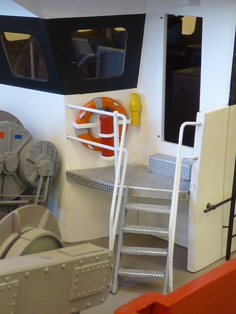
I have also finished the steps and railings. The railings were pretty fiddly as the angles were all different. However I made up templates for the railings using some garden wire to save the cost of making them from 1/16" brass by trial and error. They have been soldered up and painted and temporarily fitted to see the effect.
On the right hand side there is a yellow cylinder fitted near the door, which I think is an emergency locator beacon, which floats free if the vessel sinks or I guess you can throw it overboard beforehand as an alternative.
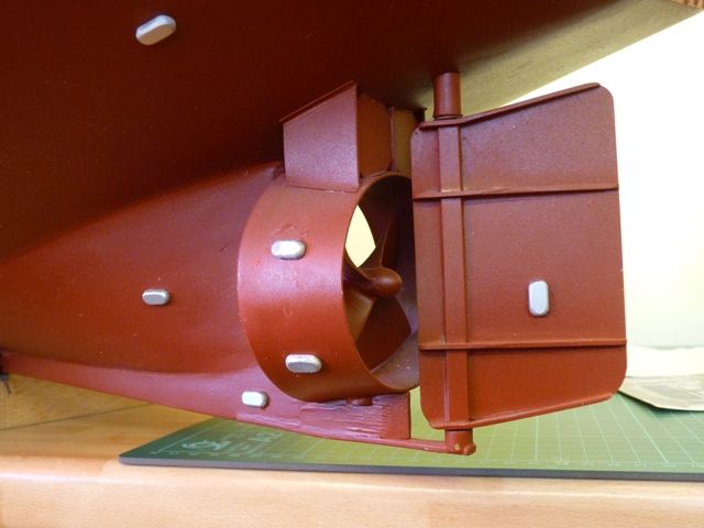
I have also started fitting the sacrificial anodes on the underside of the hull. I dont seem to have had the same problems with varnish here, maybe its adhered better to the underlying paint.
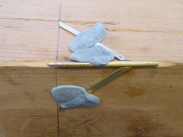
All the anodes are shaped from styrene strip by hand. Maybe I should have tried some new technology (for me) and tried casting them in resin. However its a bit late for that now, I have shaped 16 of them, only another 14 to go. I have a couple more photos to take to illustrate how they were painted and fitted but that might have to wait till next weekend.
Gareth
Gareth,
Spell binding modelling , also well photographed ,
you know your way round a camera ……..a very well done thank you for info .. ., Larry.
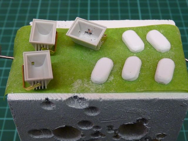
I have now fitted all the sacrificial anodes to one side of the hull and made most of the ones for the other side. They are quite an awkward shape to get hold of and tend to blow away when being sprayed with the airbrush. I have found a useful way of holding them while painting is to fit a bit of masking tape to a wooden block. Small parts can be stuck down well enough to stop them being blown off, but it does not mark them and its easy to get them off afterwards. Here are a few anodes and the lights for the back wall of the wheelhouse.
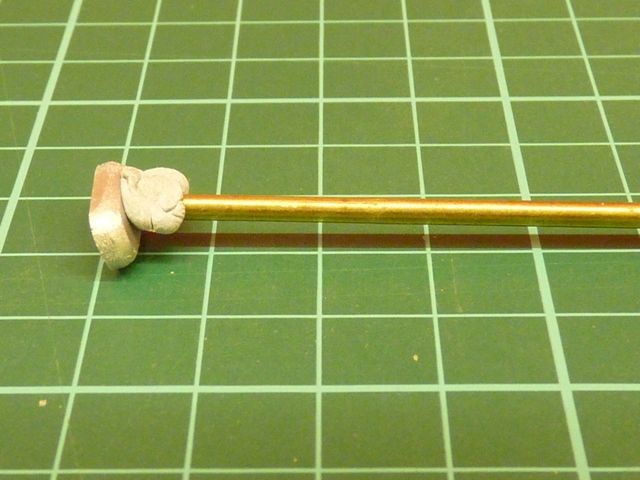
Sticking the anodes on is also fiddly as they tend to slip out of my fingers and its difficult to position them accurately. Invariably they land on the floor glue side down and bond on to the vinyl flooring immediately. I now use a short length of brass tube with a bit of Blutack on the end to pick them up and hold them in position on the hull when gluing.
The lights have now been fitted on the rear wall of the wheelhouse and the wiring connected up to a terminal strip under the wheelhouse floor. The wires run around the top of the wheelhouse edge, just above the ceiling and then down though holes drilled in each rear corner.
As you can see I have temporarily removed the steps and railings to reduce the risk of damage while messing around with all the other bits.
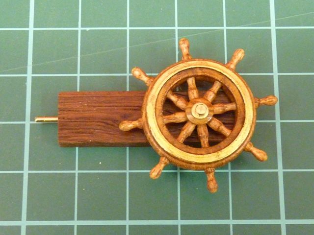
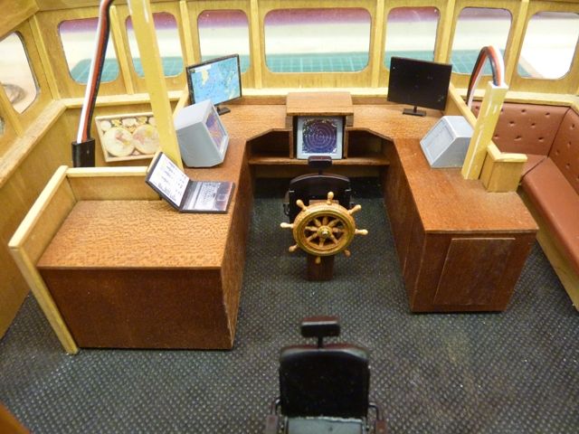
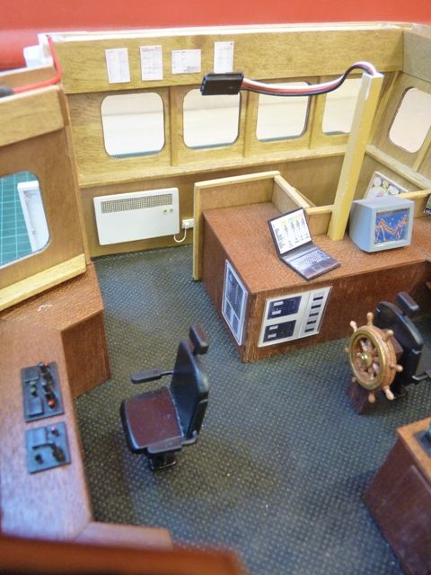
I have also made up the two swivel chairs by adapting a pait of Battlecraft units. They needed the seat cushion to be raised up and headrests added. I have also made up the ships wheel which fits just behind the forward chair.
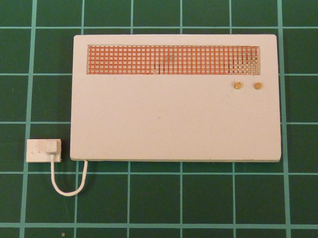
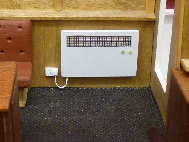
The next job was the pair of electric convector heaters which sit on each side, near the doors. These were made from styrene sheet with a cutout to locate a piece of fine chrome plated brass mesh and a couple of short bits of brass rod as control knobs. The plug and socket is another couple of small pieces of styrene with brass wire painted white to represent the electrical lead.
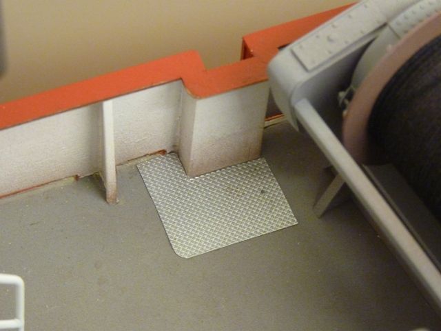
Finally I have added the tread plates to the deck adjacent to where the steps up the side of the hull meet the bulwarks.
I am now making the shelf for the TV which is fixed in the corner just above the bench seat. After that its a few more bits and pieces for the controls and displays on the consoles and walls.
Gareth
Edited By Gareth Jones on 09/02/2014 08:50:37
Gareth,
Inventive scratch building gold medal finish ,
air brush work , is first .., just gone down the air brush route , bought my self a,,AS186 COMPRESER
with two free air brushes , from KM DIRECT a uk based firm the price£61.95 with free postage,
the family all chipped in for my birthday ,,
looking to giving it ago, cheers Larry..
Stunning stuff Gareth. I use blu-tac to hold those little bits down when spraying…stops a crust forming at the bottom of whatever it is you are spraying by laying on the masking tape. Good stuff, blu-tac!
Ashley
Hey Ashley, your last comment about using Blu-Tack for airbrushing small items was exactly the right tip I needed. I'm just about to start spraying about 150 metal fittings for my Yorkshireman and I WAS going to go down the route I've always used in the past (upside down masking tape) with the usual crust forming as you mentioned. So Nice One.
Paul
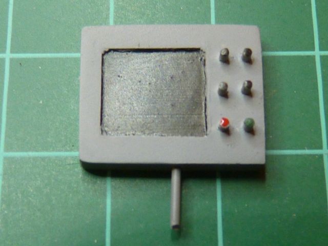
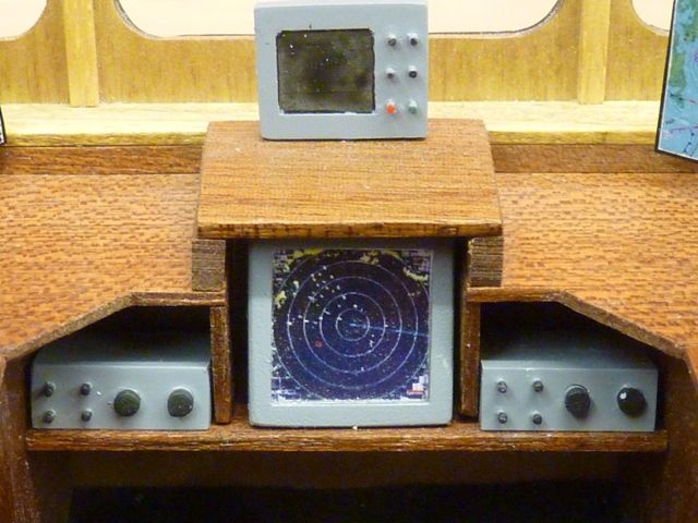
A few more bits and bobs have been added to Shemarah's wheelhouse this weekend. Here's one of the grey boxes that sits on the front console. I have still got to make the bottom part of whatever it is supposed to be.
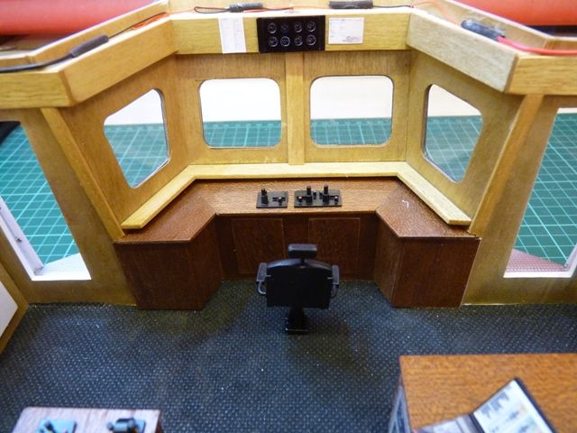
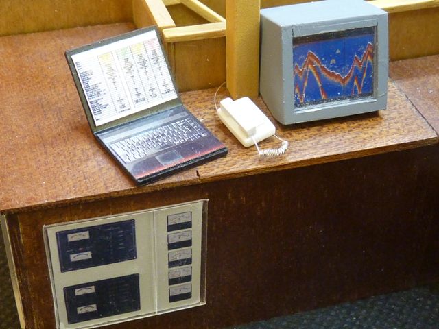
I have added the TV that sits in the right hand corner and the electrical panels that are on the sides of the left hand console. The panels were made from a composite photo of several likely bits of electrical equipment printed on to glossy photo paper. The perspex covers are made from a clear piece of styrene, glued on to the console with a tiny spot of superglue in each corner. The instrument panels have also been stuck on the top fascia above the front and back consoles. Again these are composite photos of instruments culled from the web.
There are a few assorted sheets of A4 paper stuck around the top of the wheelhouse. These are just photos of a typical A4 sheet of paper, shrunk down to 12 mm x 8 mm approx and stuck on the sides with superglue. I have no idea what the pieces of paper say in real life but the model has a copy of my car's MOT certificate, a letter about my pension, part of my wife's car insurance documents and instructions from the Yorkshire Wildlife Trust on how to look after the white cattle on Allerthorpe Common.
The rear console has now aquired the winch controls. There are still a few more bits and pieces to add but the main items required are a few 1:24 scale figures. In the past I have used Robbe figures and some from what was George Turner Models. I will have to have a look for something suitable at the Ellesmere Port show in a couple of weeks.
Edited By Gareth Jones on 16/02/2014 20:18:18
Edited By Gareth Jones on 16/02/2014 20:20:00
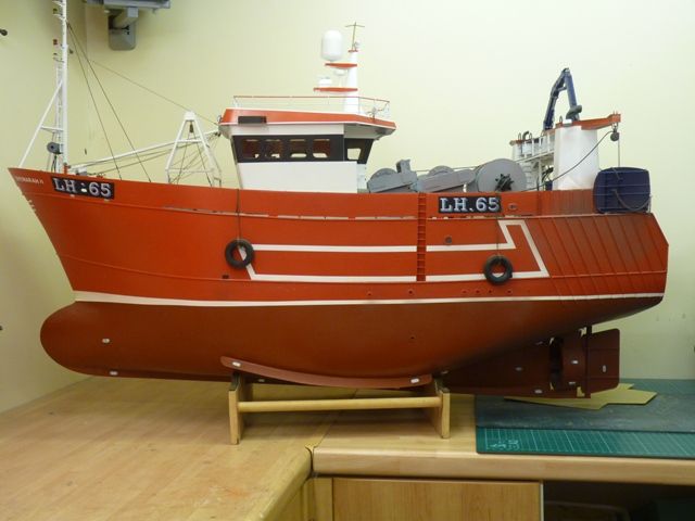
All the sacrificial anodes are now sanded to shape, painted and stuck on the hull, 14 on each side as far as I can tell from the photos of the real vessel. I have made a few spare in case I spot some places where there should be some more.
I have also made a couple more grey boxes to go on the wheel house consoles. I think these are probably radios but I may be mistaken. I can only see one of these in the photos I have, so I took the liberty of fitting one on each side.
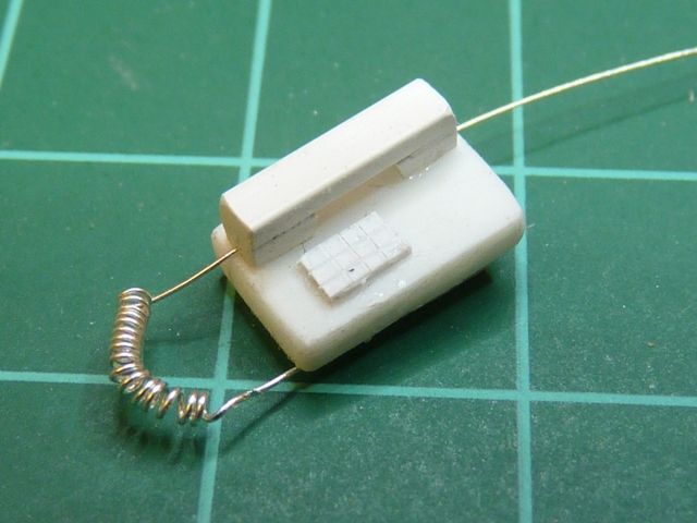
Finally one of those little touches that will probably never be seen from outside the model, and certainly not when its sailing. There are two telephone handsets on the consoles, one on the front and one at the back. Hence I have made two 1:25 scale phones, each approx 9 mm x 6 mm. They are just made from bits of styrene sheet and strip with a bit of fine wire wrapped around a drill to make the connecting cord for the handset.
Heres the phone on the front console.
Its one of those little touches that are so entertaining to point out to people. Some time ago my wife and I built a narrowboat and Elizabeth made some 1:12 scale toothbrushes, complete with bristles. Its one of the highlights of the model, either that or we are both really sad.
Gareth
Edited By Gareth Jones on 19/02/2014 20:59:40
Edited By Gareth Jones on 19/02/2014 21:00:45
This weekend's project has been the 4 fluorescent light fittings under the edges of the wheel-house roof.
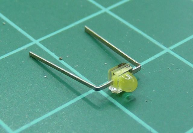
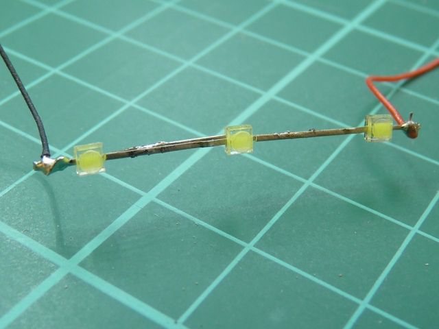
Starting with some Component Shop 2.1 mm miniature LEDs 
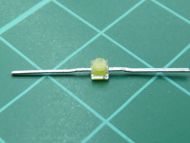
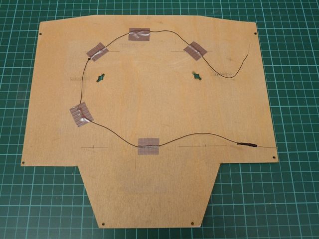
I carefully straightend out the legs and snipped the ends off so they were 10 mm long. Then I sanded a flat on top of the dome, partly to diffuse the light but also to allow them to fit inside a length of rectangular 6 x 3 translucent styrene tube.
The LEDs were then soldered together to give a strip of three lights, remembering to keep the polarity correct on all three, i.e. positive to negative. Sometimes with handling the black stripe on the back rubs off and you have to test them to see which way round they should be. The supply wires were then soldered on the ends. Its very thin single core cable, again from Component Shop. I have only one complaint, the black insulated variety is a real pain to strip the insulation off, It goes all stringy and fibrous rather than pulling off in a tube. Half the time I end up nicking the conductor which then breaks at some inconvenient moment. The red insulated variety is fine.
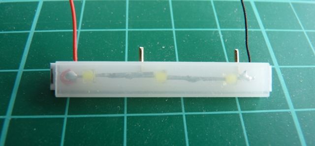
The light fitting is made from translucent tube with a strip of white styrene glued on the top and eventually fitted to the ends. A couple of brass pins fit into holes drilled in the edge along the top to attach the fitting to the side of the wheel house. A couple of holes are also drilled in the top to allow the wires to be fed out. The wire is fed out though the hole in the top at one end and the strip of LEDs pulled through the tube with the other wire, before that end of the wire is fed out through the hole in the top at the other end. TheLEDs were just a nice sliding fit, stiff enough to hold in position but not so tight you break the wires pulling them through.
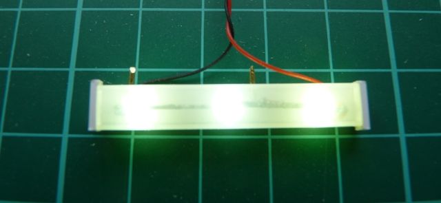
A bit of experimenting was needed to get the brightness right. Eventually I used a 470 ohm resister with each set of LEDs, running them from 12 Volts. This is a bigger resister than normal, but in comparison with the floodlights, the fluorescent lights are not so bright. Here's the effect on the bench.
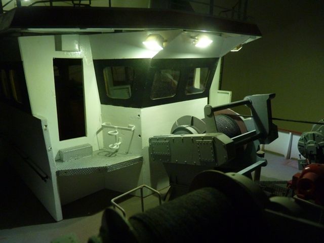
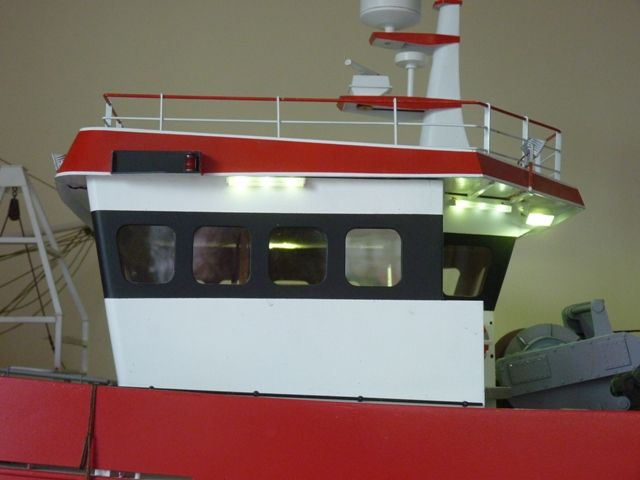
And here's the effect on the wheel house. The nav lights in the roof are not connected at the moment as the roof is just placed in position to show the effect.
Its not too bad a simulation of a 3 foot fluorescent light fitting. Maybe 5 LEDs in a row would have been better but its OK for now. They were a bit fiddly to make and I got through a few LEDs in trial and error making the prototypes. Some failed because they were handled too much and eventually broke off the connector tags. I managed to destroy three in one go when I connected them up to the 12 volt battery but forgot to put the current limiting resister in first. The next job will be the LEDs to light the inside of the wheel house and then all the lighting and electrics will be complete.
Gareth
Edited By Gareth Jones on 23/02/2014 18:35:28
Gareth. My ghast continues to be flabbered by the ever increasing levels of detail. I have had to lie down on seeing the last lot of photos.
I would be a devil and slip in something inappropriate into one of those screens. No one would notice..or would they?
Ashley
Beautiful work, way beyond my abilities, but a pleasure to admire, none the less!
Ashley,
I might or might not have done as you suggested with respect to the displays. That should generate a few close looks the next time Shemarah goes on show. Last weekend I took her for a day out at Ellesmere Port so that the famous TV star Bob Abell could have a look. It was very nice to meet you Bob and we were flattered to get our photo on the forum. However we are still astounded to hear that the Great Eastern has been chopped up.
Amy, I am glad you like Shemarah but I am sure its not really beyond your capability to build something similar.
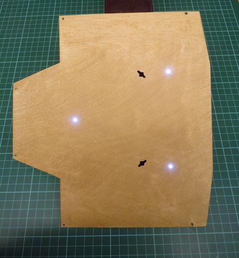
The last job I did before temporarily refitting the roof was top add three LEDs to light up the inside of the wheelhouse. I dont want something too bright, just enough to make the inside visible and give a bit of a glow when nightsailing. The LEDs just poke through the 1/32 ply false ceiling and are taped in position on the upper side.
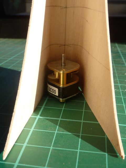
While the roof is still on for the Goole Hobbies Exhibition this weekend I have made a start on building a new version of the mast on top of the wheelhouse. I have lost count of the previous attempts, I think I am up to number 6 now. The current mast is slightly twisted and I want to hide the radar motor and wiring more completely. Here's the rear view of the current one.
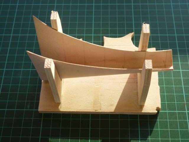
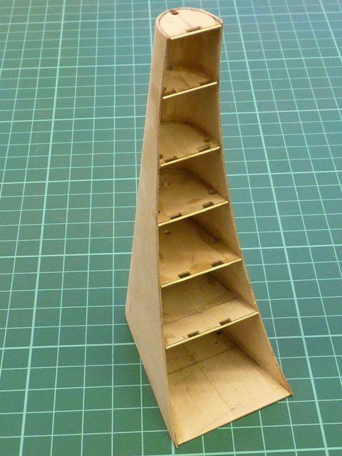
My next attempt was in styrene but that was a failure, 0.75 mm sheet was not stiff enough. The advantage of the original 0.75 mm ply is that by bending along the laminations after steaming the ply, it's flexible enough to get the tight front curve but still stiff along the vertical axis. Because the last one ended up slightly twisted and was a real pain to glue the diaphragms into, I have made a little jig this time to support the skin on assembly.
The motor to be used is a little Robbe 500:1 geared motor which I already had stored away, having used it in another application for a while. Unfortunately, while unsoldering the wires this morning I managed to melt the plastic plate that holds the brushes in place and pulled the complete brush out from one terminal – which is probably a terminal error as far as this ones concerned. Looks like I might have to order another.
The motor will fit completely in the bottom section of the mast and will be hidden by a plate across the back of the base section. I am planning to fit one or two lengths of plastic tube down the mast to act as conduits for the wiring from the lights on the top of the mast. I hope to get the mast finished this week and then its off with the roof again to finish off the inside of the wheelhouse and install the crew. After that its mainly the antennas on the roof, a bit of weathering here and there and the model will be finished – although I am sure I will think of something else to do before its next public appearance.
Gareth
Hello Gareth
I like the fluorescent lights!……They look really convincing
I also like the ceiling lights too……..A great idea using a drilled hole to get the size down!
It was a pleasure meeting Elisabeth and yourself at Ellesmere Port and seeing Shemarah and Ariel….With the secret keel!
Geeez…….And I thought the GE keel was ugly!
Capt Bob………..Star of the silver screen…….As you quite rightly mention
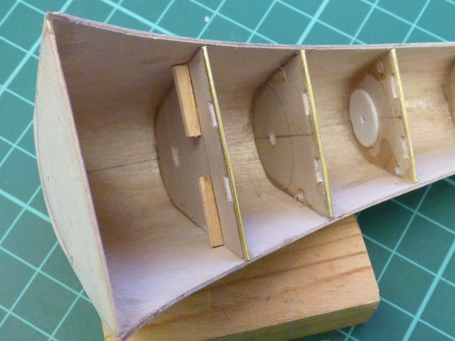
This week I have been building the new mast, using the same materials as the original, 0.75 mm ply. All the diaphragms have been fitted, along with the hand holds up the rear edge.
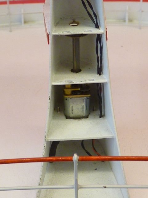
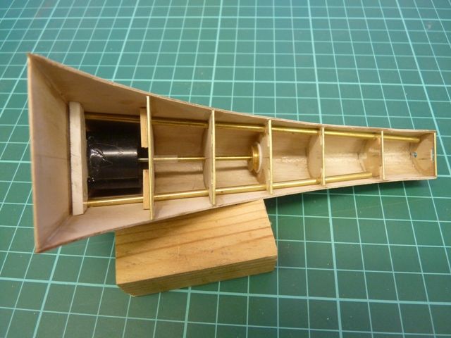
The radar motor now fits completely in the bottom section and will be covered by another small sheet of ply when the mast is complete. The drive shaft runs up the centre of the mast and there is a small disc of styrene glued to the underside of the centre diaphragm to act as the upper bearing.
I have fitted two lengths of brass tube to simulate the electrical conduits for all the wiring that runs down the inside of the mast. Its a bit oversize to scale but it had to be big enough to get the wires down from the lights on the top of the mast. In the picture below you can see the radar drive shaft and pulley. The belt will exit through a slot in the front of the mast, hidden under the platform that supports the radar head. The shaft is connected to the drive motor by a short length of palstic tubing which also acts as a flexible coupling.
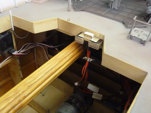
Another job that was not really anticipated is to modify the electrical connector between the hull and the wheel house. At the moment the plug in the wheel house is fixed but the socket from the hull is on a flying lead. Originally, when the wheelhouse was relatively simple and the deck was uncluttered it was reasonably easy to make the connection. Now that the winches have been fitted to the hull and the steps and railings are on the wheelhouse its a struggle to make the connection without damaging something. Since Shemarah is so heavy and needs to be put in the water with the wheel house removed I need to modify the connection so that it is made automatically be lowering the wheelhouse onto the hull. Some form of guide will be needed and I have a plan, just not had the time to build the parts yet.
Gareth
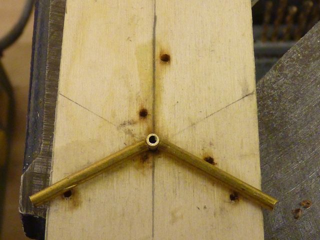
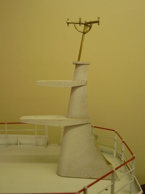
I have now made the platforms that project from the front of the mast and this morning started on the aerial array that fits on top. The aerial support has three arms at 120 degrees to each other but they sit on a plane at 80 degrees to the vertical support to allow for the fact that the mast slopes back 10 degrees. It may seem complicated but all should become clear soon.
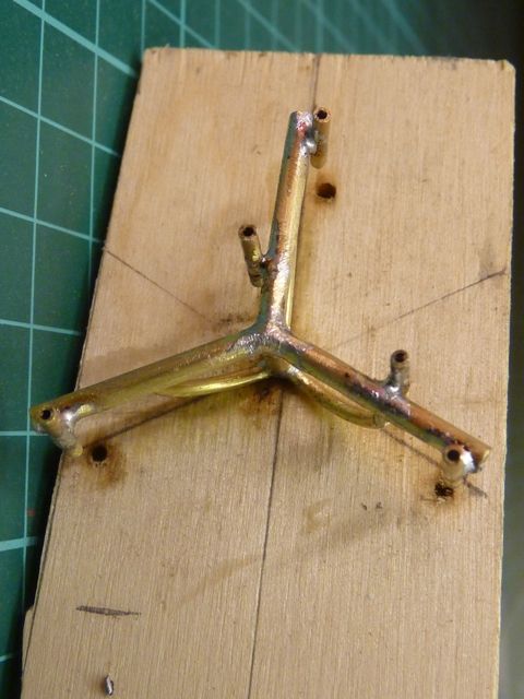
As usual in this sort of fitting I made a jig to hold the parts while soldering them. The vertical support goes theough a hole in a piece of 6 mm ply. The hole is drilled at 80 degrees, not vertically though the ply. The arms are then laid alongside on the marked lines to get the right layout. Here you can see two of the arms laid around the upright, although this photo was taken later just to illustrate the method.
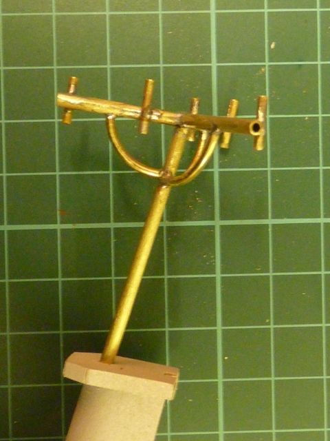
After all three arms had been soldered on to the upright I drilled 5 additional holes in the ply to locate the 1/16 brass tube which forms the bottom of each individual antenna, so they could be soldered on the arms. Finally I soldered 3 support brackets which lie under the arms.
The essentials in soldering this sort of fitting are to make sure it is clean and shiny, apply a little flux and 'tin' each of the parts with a little solder in the area they are to join. Then make sure your soldering iron is really hot and just touch the joint quickly with a little additional solder. If you take too long in getting the heat into the assembly it all falls appart as the solder in the other joints melts. Sometime you need three hands to hold everything but usually with a bit of support from a jig its possible to hold and locate everything in the right place.
The aerials themselves are make from plastic coated stranded steel wire. Its stiff enough to represent the aerial but flexible as well so if you catch it on something it just flexes out of the way and springs back. A bit of solid brass wire would either stay bent or snap off. There is also probably less risk of poking yourself in the eye if you get too close. Its all ready for painting now, which is the job for the weekend.
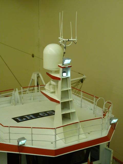
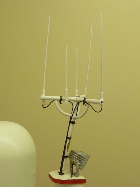
A bit more progress towards finishing the wheelhouse this week. The registration letters have been painted on the wheelhouse roof and the mast has been painted and wired up.
I have made a first attempt at the wiring to the aerials on the top of the mast. Just two more to do and some thinner tape to wrap around them to simulate the tieraps. I also need to do a bit of touching up as the white paint has flaked off the brass tube in a couple of places.
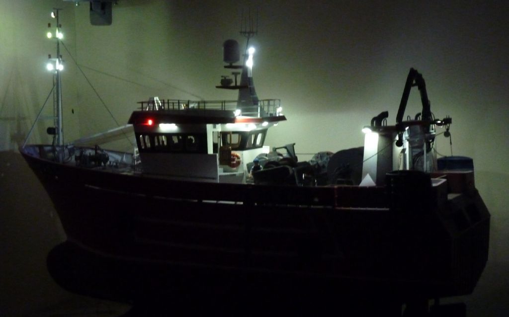
Finally a slightly shaky picture of Shemarah in the workshop with all the lights on, except for the ones inside the wheelhouse. There are 31 LEDs in the lighting system and it only takes about 1/4 watt to power it all, 0.2 amps at 12 volts.
Next job is to fix the 3 tall whip aerials on top of the wheelhouse plus several smaller ones that seem to be positioned around the edges. After that its a few more details to add inside, the ships bell to fit, a couple of tannoy loudspeakers, which I painted this weekend, and then the crew. That will just leave a bit more weathering here and there before its finished.
Gareth.
Well done, Gareth
Lovely model!…..We are going to miss your regular postings of the Shermarah build, on it`s completion
How will you follow this class act?
Bob
Thank you Bob.
I might start a new thread for my next model which will be something completely different. At the moment the plan is to build two 1/16 scale Sheffield sized hulls, partially concurrently, partially consecutively. One of them will be finished as a Humber keel, the other as a sloop. Its going to be joint project with Elizabeth.
Gareth
What?…….Do you realise how big Sheffield is?
Never heard of a Humber keel etc
What size in real terms?
Bob
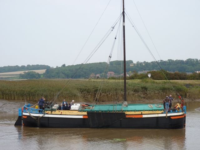
If you haven't heard of a Humber keel you haven't lived Bob. Heres a link to a website which will tell you all about them. **LINK**. I will post a photograph tomorrow. They were not the most elegant or beautiful sailing ships but have a long and illustrious tradition in our part of the world.
The keels and sloops were built to standard sizes to fit in the locks on the inland waterways on which they were to trade. Sheffield sized is one of the most commonly built versions and was nominally 61 feet 6 inches long and 15 feet 6 inches beam. The model will be about 48 inches overall length and height. However they were designed to allow the mast to be lowered quickly and easily so it will be possible to drop the mast on the model so it will fit in the car conveniently.
Gareth
Thank you Gareth
I like it…..I like the shallow curved blunt nose…….. Saw similar at Ellesmere and liked it then
Could you not make your model much larger?……Like 8ft?……… 4ft is rather small and will look very insignificant…..No matter how much fine detail you add to it?
Make it in two halves for transport?
A big motorised barge was my secret ambition, until recently
Give it some thought?…..You could make 4 ft each?
Bob
Hi Bob,
Thanks for the suggestions but 4 foot will be plenty big enough, and more significantly heavy enough. If it was eight feet long it would need a mast around 8 ft 6 inches high which is just not practical. We already have a 6 foot 6 inch long sail box for Elizabeth's Marblehead yachts and that only just fits in the car.
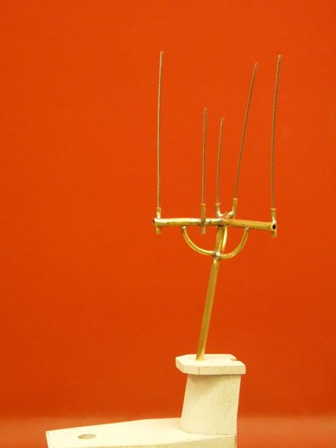
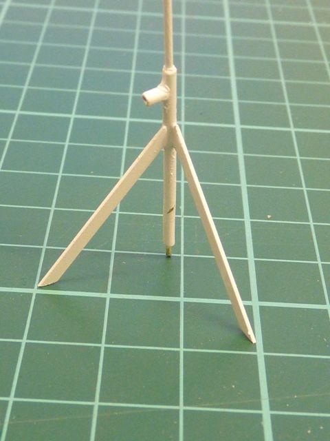
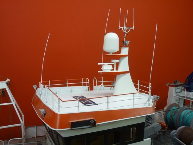
Shemarah has progressed a bit further over the last couple of weeks. I have made the 3 long 'whip' aerials which fit on the wheel house roof. They are each mounted on a tripod arrangement which is difficult to see in detail on the photos I have so I have had to improvise. Here is the tripod base made from brass tube and strip.
It was quite difficult to solder together so, as usual I had to improvise a little fixture to hold the bits in the right relative position while soldering.
The aerials themselves were made from some more plastic covered stranded fishing trace, painted white. However the paint has not bonded very well and I think I will have to rough up the plastic covering a bit to give it better adhesion. However the aerials look pretty good. I have yet to add the connecting leads and the black box that attaches to the railings at the bottom of each unit.
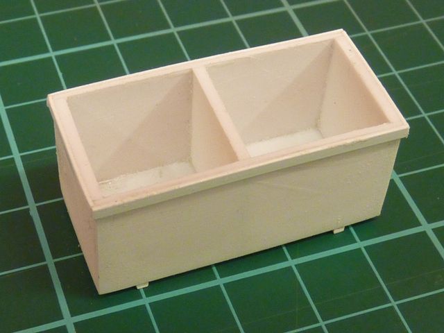
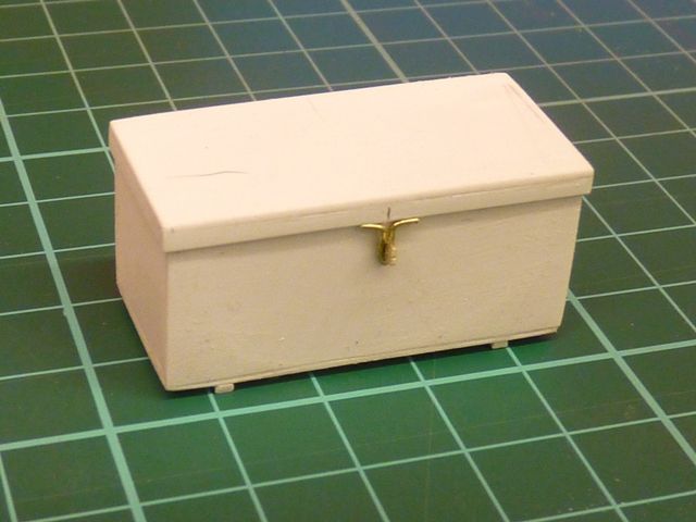
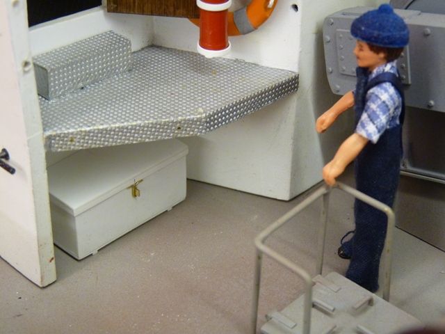
The next job was the lockers which fit under the rear wheelhouse platforms. They are simple styrene boxes with a simulated lid and latch.
Here's one of the crew members admiring the finished article. As usual they are retained on the deck with a couple of 1/32 brass pins for the moment.
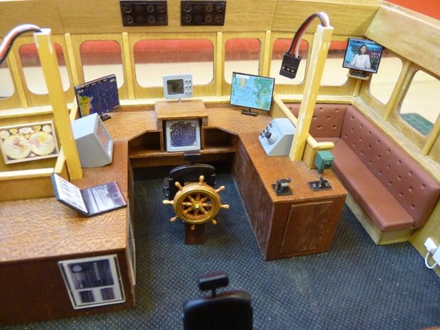
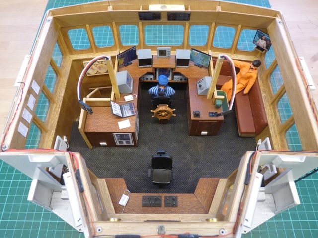
The inside of the wheelhouse has been finished with the last couple of display screens added and the crew glued into position. The real wheelhouse looks more cluttered but since you cant see inside the model very well it will do, at least for now.
I have also finally fixed in place the electrical connector for the wiring to the wheelhouse light, radar and speaker. It was a bit fiddly getting it in the right place. I was expecting to have to put a couple of guide pins and tubes in each half to locate them when the wheelhouse is fitted but the coaming on the deck works fine and its just a matter of pushing the wheelhouse down on to the connector. It take a bit of wiggling to free it but its not too difficult. It's certainly easier than trying to hold the wheel house up while fitting the connector on the end of a flying lead.
Finally I have fitted the two drain pipes which run down on either side of the wheelhouse.
I am getting near the end now, only about half a dozen minor jobs to do, although there will probably be a few extra ones I have forgotten.
Gareth
Code of conduct | Forum Help/FAQs
Home › Forums › Scratch build › Topics
Started by:
Alasdair Allan
in: All things floating
Colin Bishop
Started by:
Ray Wood 3
in: Sailing Models
Ray Wood 3
Started by: Tim Cooper
in: Soapbox
Richard Simpson
Started by:
ashley needham
in: All things floating
ashley needham
Started by: Stephen Garrad
in: All things floating
Tim Cooper
Started by:
Ray Wood 3
in: Scratch build
Colin Bishop
Started by:
Colin Bishop
in: All things floating
Colin Bishop
Started by: Tim Cooper
in: All things floating
Richard Simpson
Started by: Bob Abell 2
in: Scratch build
Ray Wood 3
Started by: Tim Cooper
in: Build Blogs
Tim Cooper
Started by:
Chris Fellows
in: Build Blogs
Boiler Bri
Started by:
Boiler Bri
in: Build Blogs
Boiler Bri
Started by: Tim Cooper
in: R/C & Accessories
Tim Cooper
Started by: Charles Oates
in: Collectors’ corner
Dodgy Geezer 1
Started by: harry smith 1
in: Collectors’ corner
harry smith 1
Started by:
Colin Bishop
in: Full Size Ships
harry smith 1
Started by: Queequeg Quint
in: All things floating
Colin Bishop
Started by: Queequeg Quint
in: Beginners
Tim Rowe
Started by:
Richard Simpson
in: Soapbox
Richard Simpson
Started by:
Alasdair Allan
in: All things floating
Richard Simpson
Started by: Len Morris 2
in: Soapbox
Richard Simpson
Started by:
Alasdair Allan
in: All things floating
Alasdair Allan
Started by: harry smith 1
in: Collectors’ corner
Richard Simpson
Started by: mejt2026
in: Beginners
Richard Simpson
Started by: Stephen Garrad
in: Scratch build
Stephen Garrad