Hunstman 31 by Tim Rowe

Advert

Hunstman 31 by Tim Rowe

Home Forums Build Blogs Hunstman 31 by Tim Rowe

  • This topic is empty.
Viewing 14 posts - 26 through 39 (of 39 total)
  • Author
    Posts
  • #88315
    Chris Fellows
    Participant
      @chrisfellows72943

      Blimey Tim the keel is shallow. Won't be much left when you've profiled it for the skins! Mine are massive in comparison but as you know I don't do light!

      Following with interest.

      Chris

      Advert
      #88322
      Eddie Lancaster
      Participant
        @eddielancaster

        Hi. Tim, another fine and informative build, you must almost spend as much time setting up and taking photos as you do actual building laugh, but I am not complaining, please keep them coming.

        Regards.

        Eddie.

        #88324
        Tim Rowe
        Participant
          @timrowe83142

          Thanks Chris and Eddie.

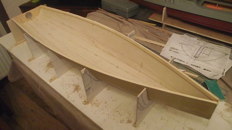
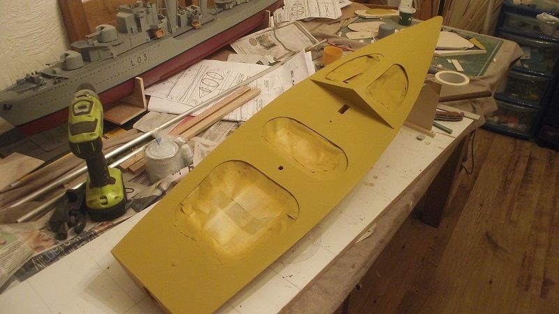
          That's the key to the whole concept. Individually the parts are weak and floppy but when assembled they are support each other. The tricky thing sometimes is the bit in the middle and why I am so keen on jigging. I have done the same thing on the keel of the Sealane. Galileo has no internal keel or chine stringers although those joints were reinforced with glass and epoxy. Initially it had no internal structure until I added it but only where I reckoned it was necessary.

          There is some logic to keeping the hull light in my case when you see the amount of gubbins that goes with that big lump of a motor. Probably the flywheel weighs more than the equivalent electric motor then I have to add fuel tank and plumbing, cooling system, exhaust, throttle servo, battery and the list goes on!

          Bet your boats will last longer than mine in the long run Chris

          Tim R

          #88325
          Eddie Lancaster
          Participant
            @eddielancaster

            Hi. Tim, I know what you mean about a hull with no internal frames, the Boxkite was like that, with only one frame carrying all the internal gubbins,mast box, radio, servo etc.and that was only fixed to the gunwales, deck and fin box

            dscf3766.jpg

            dscf3781.jpg

            The top of the frame supports the foredeck.

            Regards.

            Eddie.

            Edited By Eddie Lancaster on 24/05/2020 12:30:35

            Edited By Eddie Lancaster on 24/05/2020 12:32:39

            #88329
            Ray Wood 3
            Participant
              @raywood3

              Hi All

              The reason the old Aerokits boats were designed an built like brick outhouses , was to withstand the force of somebody with a starting cord trying to pull the engine over !! Maybe slightly less strength required these days with a vee belt round the flywheel and an electric starter 😄

              Regards Ray

              #88331
              Tim Rowe
              Participant
                @timrowe83142

                Hi Ray

                That's what I am doing. There will be a belt permanently tucked under the flywheel so that I can pick it up with an electric starter. I have a few of those at various sizes. This is not a big engine either.

                Tim R

                #88334
                Dave Milbourn
                Participant
                  @davemilbourn48782

                  That's the key to the whole concept. Individually the parts are weak and floppy but when assembled they support each other.

                  I've been struggling to find the right words, Tim, and here you are with exactly what I was trying to say about designing a model around the material. Thanks for that!

                  Dave M

                  #88338
                  Chris Fellows
                  Participant
                    @chrisfellows72943

                    Hi All

                    Yes, I understand frames and structures etc., in fact I've got a steel calculation to do for someone taking a wall out in their house, and could build lighter than I do but I get some satisfaction from building a hull with a bit of weight to it.

                    Overall weight isn't an issue with the size of boats that I'm building and with the power of brushless motors getting them to perform isn't an issue either.

                    Of course I'm saying all of this without one of my creations actually seeing water (What do you mean Dave that we probably never will!) and so if I stop posting and take up knitting you know why! smiley

                    But I'm enjoying my builds which is what it's all about.

                    As others have said Tim, your builds are really interesting with your attention to detail, ways of doing things and modifications etc. rather than just assembling things. I think part of my cavalier attitude to building models is because all my working life involved attention to detail and for my hobbies I don't have to do that unless I want to.

                    Chris


                    Edited By Chris Fellows on 24/05/2020 15:58:12

                    #88339
                    Eddie Lancaster
                    Participant
                      @eddielancaster

                      Talking of weight I have just weighed our two hulls with the glass and resin on and rubbed down they weigh in at

                      389 grams and 390 grams each.

                      Eddie.

                      #88353
                      Chris Fellows
                      Participant
                        @chrisfellows72943

                        That's just not good enough Eddie! Check again when finished, they'd better be exactly the same!

                        Breaking news, two of my builds have now seen water! laugh

                        Tim – sorry for keep hi-jacking your thread. Will restrain in future.

                        Chris

                        #88354
                        Tim Rowe
                        Participant
                          @timrowe83142

                          Chris

                          You know you are always most welcome in my threads and congratulations.

                          Tim R

                          #88364
                          Tim Rowe
                          Participant
                            @timrowe83142

                            Some more layout work before sticking anything together. Actually the two halves of the keel have been stuck together and apart from the cockpit that's about it.
                            p1160222.jpg

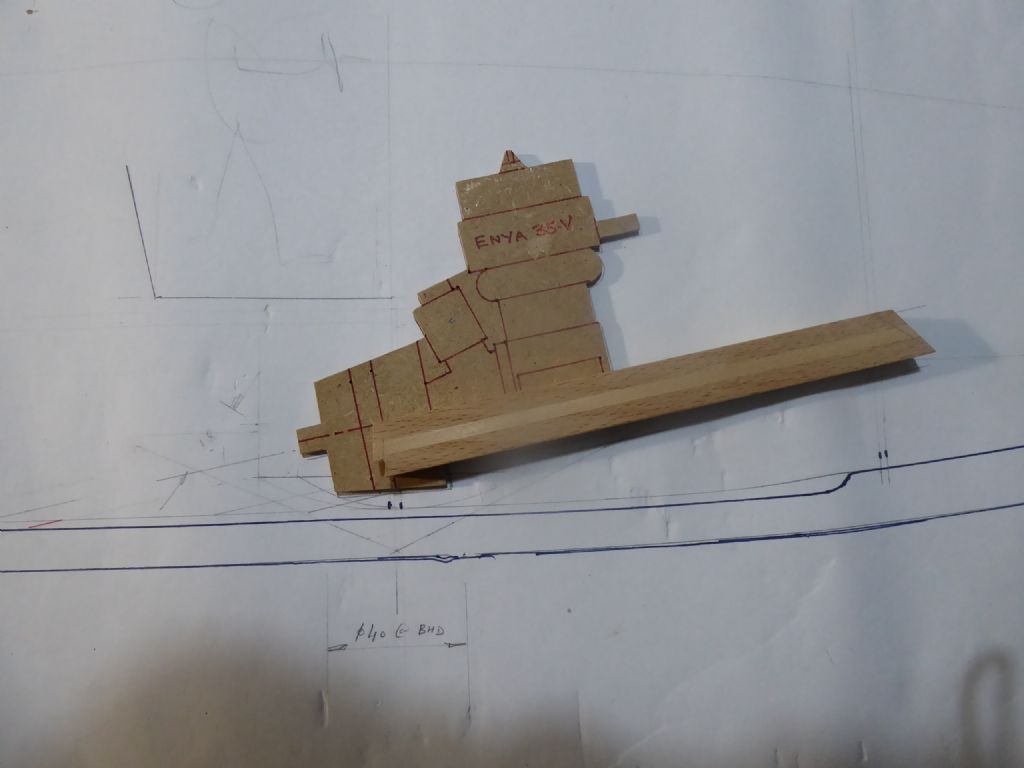
                            Here's the shadow engine on the bearers. The bearers have been spaced quite a bit wider than the actual engine mounts and the idea is that the engine sits on two aluminium plates to make up the difference. The fixings to the bearers will always have the same pitch but if I ever want to change the engine, all I have to do is make another set of adaptor plates. The plates are 3mm thick and I have allowed that thickness when setting out the height of the bearers. The bearers are beech and as hard as nails. They had grooves in them because they are for aircraft undercarriage piano wires but they have been repurposed by filling the groove with some hard white wood hence the two-tone effect.
                            p1160223.jpg

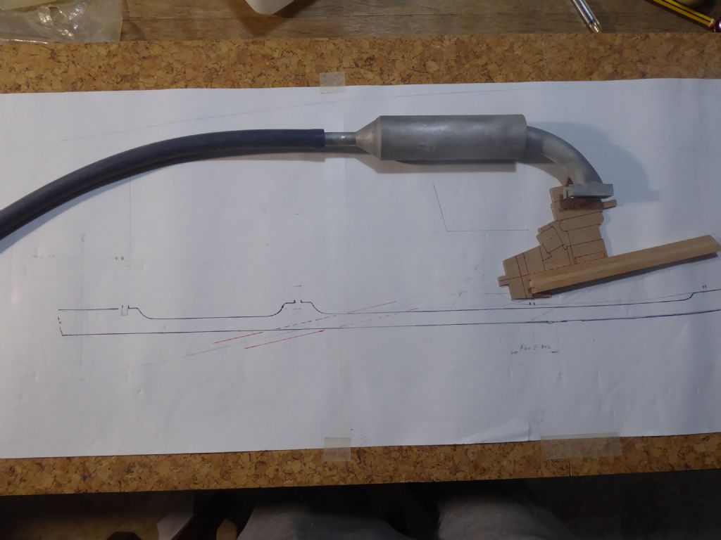
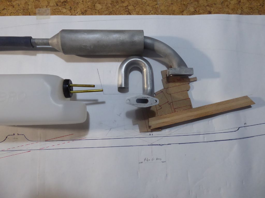
                            Here is the silencer and the silicone tube exhaust tail. The silencer arrived in a lucky-dip job lot I bought some time ago. It is aluminium. I have no idea how it will affect the performance of the engine but that's for later.
                            p1160225.jpg

                            Same job lot and I have a rather nice exhaust riser. I have to adjust the pitch of the holes on the riser to suit the engine or I may make an adaptor. The flange on the silencer will be cut off and the two parts joined with silicone tube. I am going to bright polish the exhaust parts to add a bit of bling. There were bright shiny parts on the Ford Mermaid and Sabre engines that went into a lot of the Faireys.

                            Also showing is the fuel tank. Relatively speaking it is quite large for the engine which should give me a decent duration if I don't have to use full throttle all the time. It is an American Du-Bro tank marked in US fluid ounces. No idea what that is but there are 16 of them.
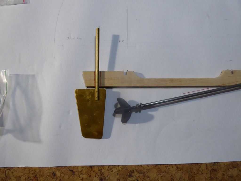
                            p1160232.jpg

                            The rudder is as far aft as I can get it. It overhangs the lower part of the transom but is inside the top line of the transom due to it being raked. This has allowed me to get the engine further aft and to tweak the shaft angle.
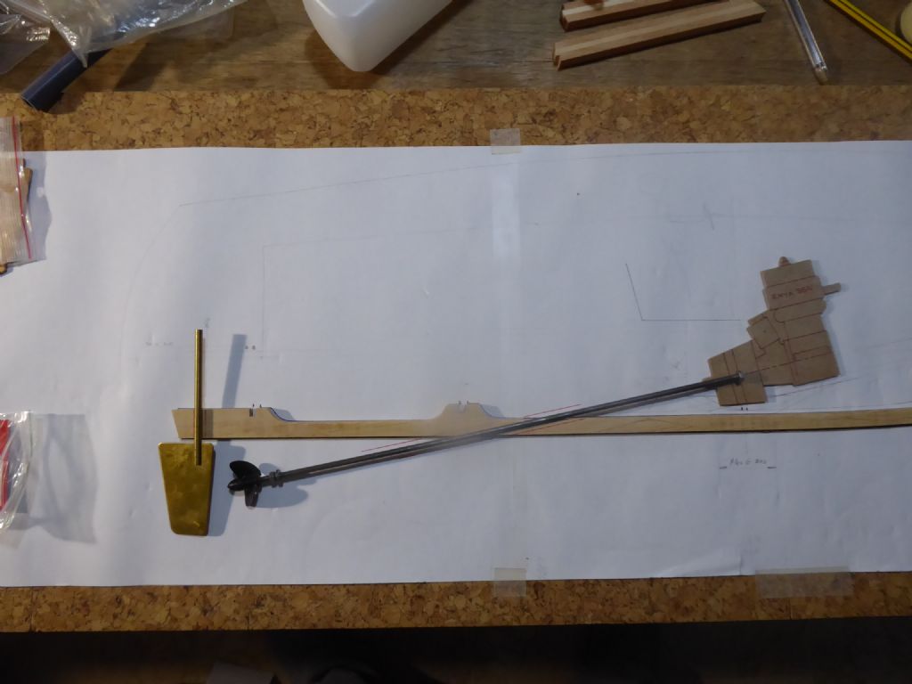
                            p1160233.jpg

                            Roaring ahead now with the shaft lined up. Somewhere in there I will have to fit a scoop for the water cooling pick-up. The shaft and tube is too long but I could easily sort that out. I don't know however whether it is any good or whether I should buy something better. Ideally it would like to have a short tube and run the shaft in a bearing in a P bracket like full size. I shall be picking brains on that later as modelling wise this is new to me.
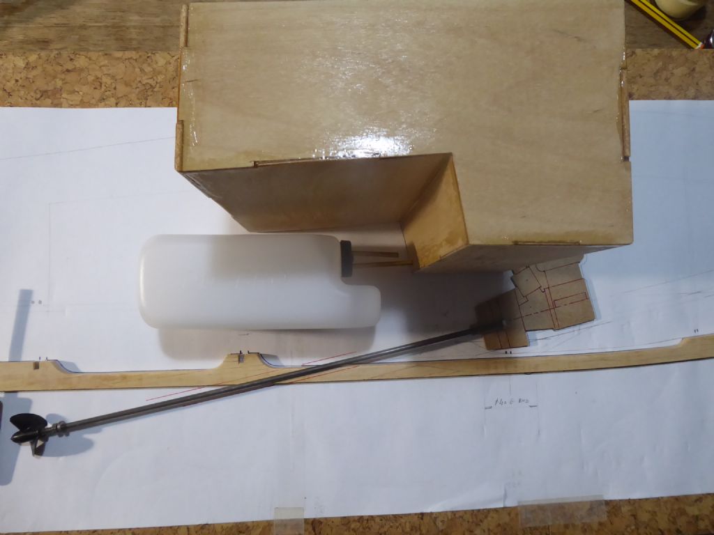
                            p1160234.jpg

                            Final check to see if the cockpit will miss the bits. The photo is biased and in fact the engine is clear from the front of the cockpit with plenty of breathing room around the carb. You can now see that the tank goes about 1/2 way through a frame and is supported by the cut-out. It will need a steady at the front when everything is finally being assembled for real.

                            I like to try to arrange things to have dual purpose and in this case the bulkhead avoids me having to make a separate cradle and keeps everything nice and simple inside.

                            I'll have to do some more building now as this is about where I am.

                            Tim R


                            Edited By Tim Rowe on 24/05/2020 20:26:19

                            #88369
                            Chris Fellows
                            Participant
                              @chrisfellows72943

                              Hi Tim

                              Raboesch do a maintenance free prop shaft with an exposed inner shaft with a bracket that can be cut down for a P or Y. Only do it in 4mm though, but I guess as your shaft is relatively short that would be OK? And ModelBoatBits do P and Y brackets that will support the inner shaft as well as an 8mm bore one.

                              Cheers, Chris

                              #88374
                              Tim Rowe
                              Participant
                                @timrowe83142

                                Thanks Chris

                                I will do some research. I think I have to use something better than I have got

                                Tim R

                              Viewing 14 posts - 26 through 39 (of 39 total)
                              • Please log in to reply to this topic. Registering is free and easy using the links on the menu at the top of this page.

                              Code of conduct | Forum Help/FAQs

                              Advert

                              Latest Replies

                              Home Forums Build Blogs Topics

                              Viewing 25 topics - 1 through 25 (of 25 total)
                              Viewing 25 topics - 1 through 25 (of 25 total)

                              View full reply list.

                              Advert