The world's leading magazine for all model boating interests
A class yacht – Serica II
A class yacht – Serica II
Home › Forums › Sailing Models › A class yacht – Serica II
- This topic is empty.
-
AuthorPosts
-
11 March 2017 at 19:02 #70254
Gareth Jones
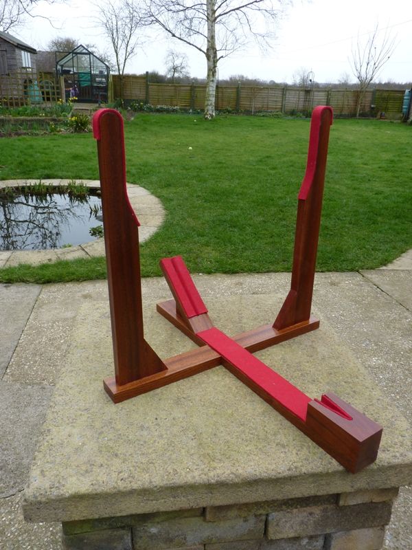
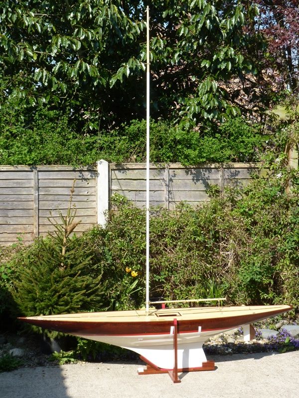
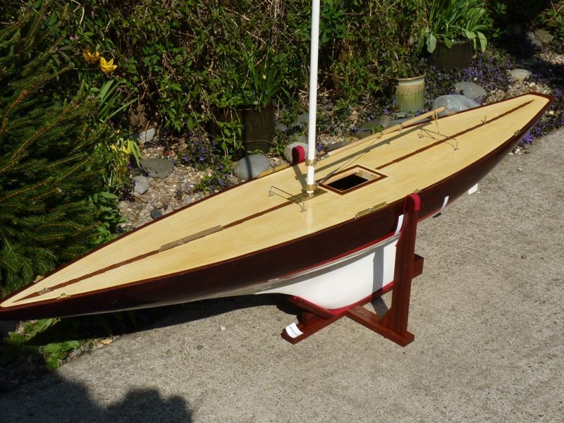
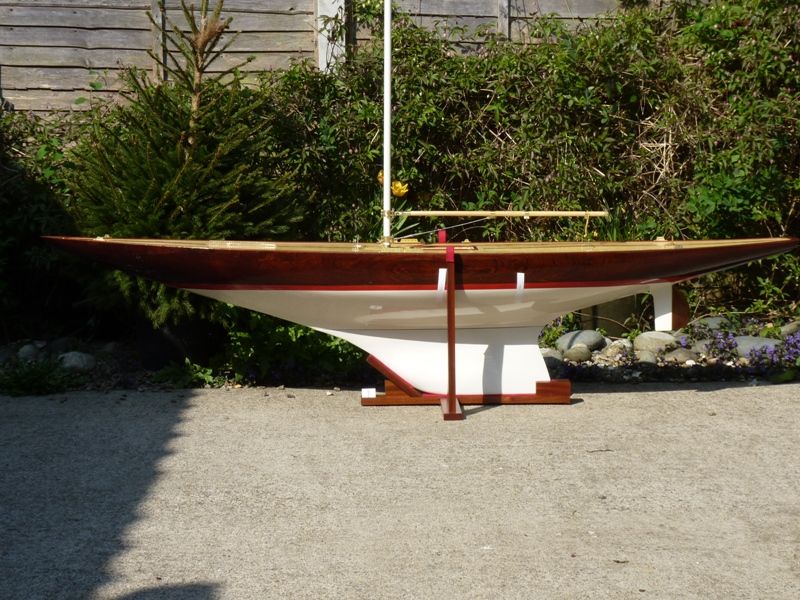
Participant@garethjones79649Before fitting the keel I needed to make a stand for Serica as none of our existing ones is big enough. About 3 years ago I bought a job lot of 12 pieces of Sapele, 20 mm x 50 mm x 1200 mm and have made about half a dozen stands so far, all to the same basic design. Serica's will be the last one as I have now used up my supply of timber. Here is Serica's stand in our back garden, ready for its first use.
11 March 2017 at 19:23 #70256Gareth Jones
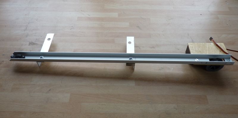
Participant@garethjones79649Serica will be a dual control model. It was designed in the days when free sailing with vane steering was the norm and this will be an option. However for practical purposes, there are very few venues suited to that nowadays so radio control of the sails and rudder has to be an alternative option. The sail winch and rudder servo have to be fitted discretely to preserve the vintage appearance of the yacht. I will be using a Graupner drum type sail winch with a closed loop inside the hull. This is built up as an assembly on the bench and then slid in through the single hole in the deck, which is only six inches be three. However given the space inside the hull, its surprising what can be manoeuvred in. Here is Serica's winch, partially made up, still to be fitted with the cord loop to which the sail sheets attach. The assembly is attached to the two keel bolts by the aluminium angles.
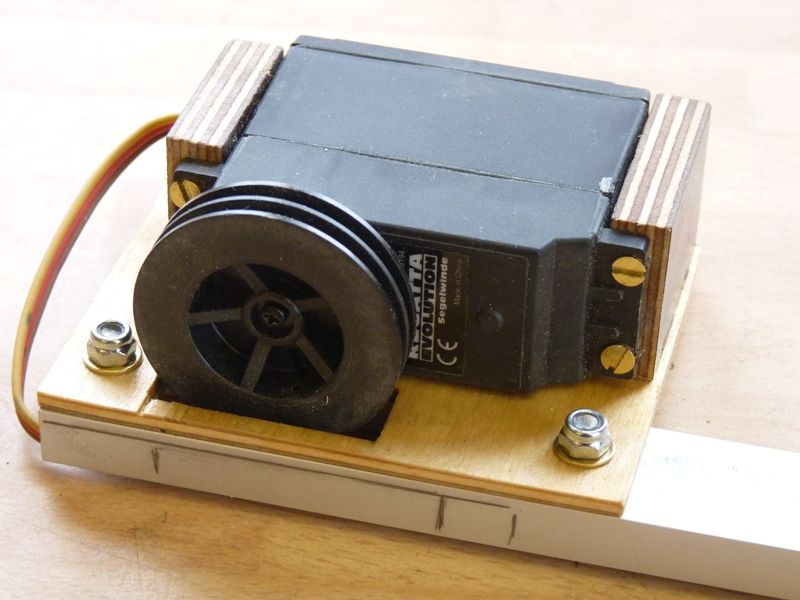
Here is another view showing the sail winch itself, must get some longer screw though, as there is not the regulation 1.5 threads showing through the stiffnuts.
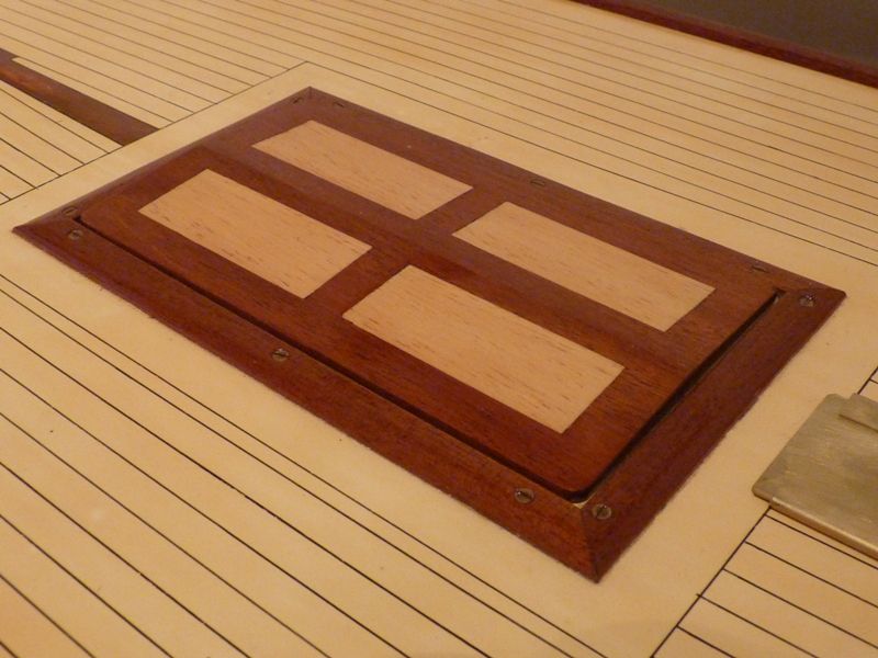
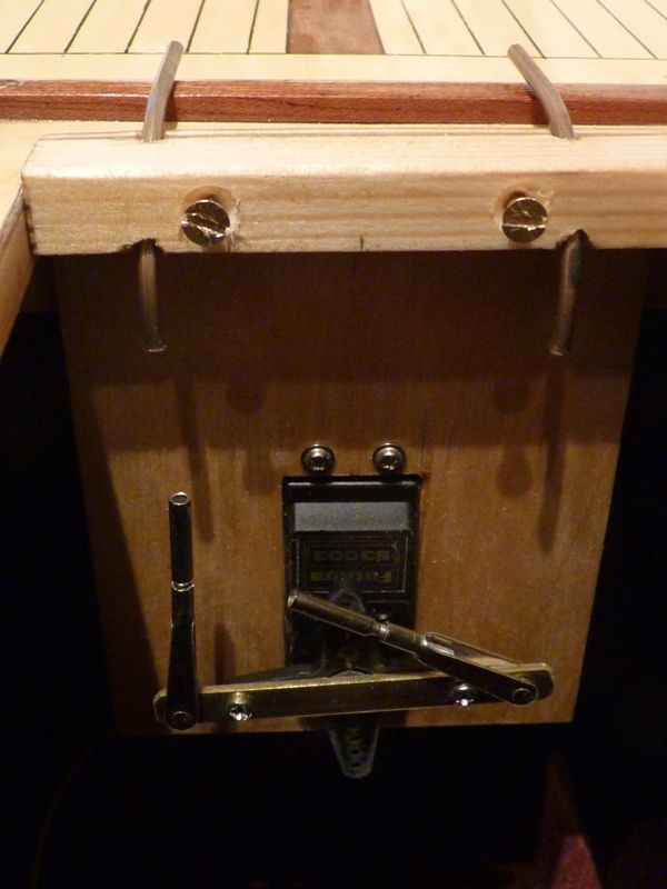
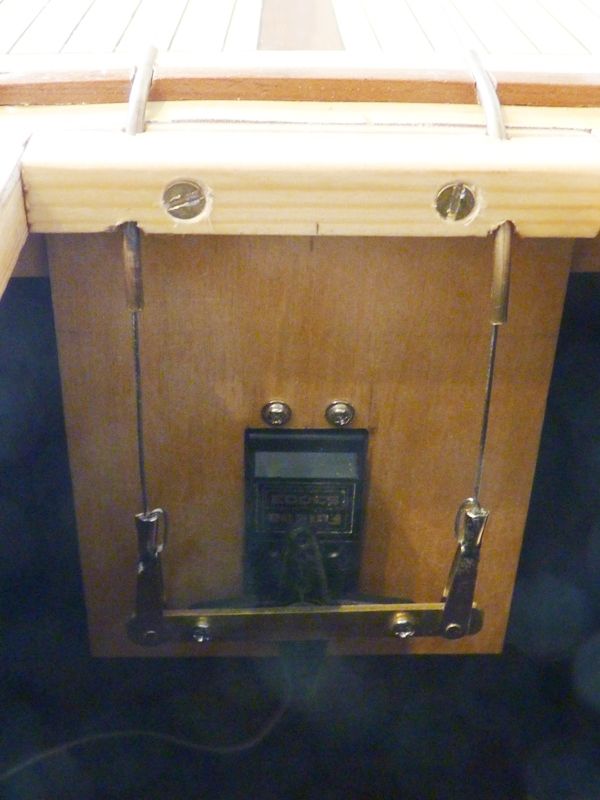
Normally I fit the rudder servo inside the hatch at the aft end with the servo arm on top and a connection back to the rudder post by a closed loop pair of wire cables. This would not be easy on Serica as the hatch cover is very thin and inset into a thin coaming on the deck. I decided on an alternative design with the rudder servo turned through 90 degrees and mounted aft of the hatch. The control wires will pass through a pair of brass tubes to guide them round the 90 degree bend. Here is the existing hatch, it was beautifully made by John Gale and I did not want to replace it or marmalise it too much.
Here is the rudder servo installation mounted on a ply plate attached to the rear of the access hatch opening. It needs to be removed before the sail winch can be installed or removed but its only held in by two brass screws at the top.
I need to cut a couple of slots in the coaming for the brass tubes to fit in so the hatch will seat properly in place. If the yacht is sailed on the vane I can remove the rudder servo assembly by removing the top two screws and blank the slots in the coaming with a bit of rubber cut from a length of O ring material.
11 March 2017 at 19:59 #70257Gareth Jones
Participant@garethjones79649The next job was to float Serica in the pond to check that the keel joint is watertight and to measure the waterline length which will then allow me to calculate the permitted sail area. I plan to order the sails from Nylet but these will take some time to arrive because they will have to be purpose made so I want to get the required size defined as soon as possible so I can send the information to get a quotation for the price and delivery.
I weighed the hull, complete with radio gear, but no battery on two sets of bathroom scales and got an average weight of 55.4 lbs. I weighed the rig of a 10 rater that Elizabeth owns which gave me an estimate of about 2 lbs for the mast, booms and sails on Serica. Including the weight of the hatch, battery, vane and deck fittings I reckon Serica will weigh about 58 lbs in vane configuration and 59 lbs in radio control mode. I made up the difference in weights with some ballast, namely three tins of baked beans and a bit of lead sheet.
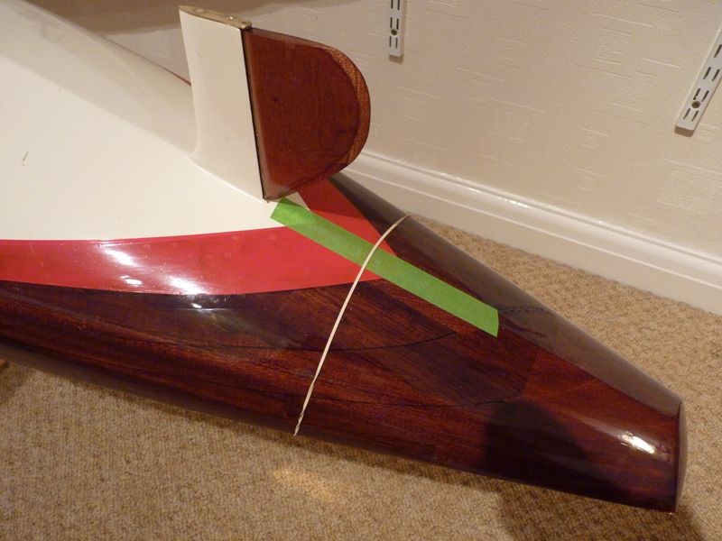
Measuring the waterline length is a bit tricky in a pond so I came up with a cunning plan using masking tape and a rubber band. I put a piece of masking tape along the bottom centre line where the water line was expected to cross. The rubber band can be moved back and forth while the boat is in the water until it just sits at the waterline point at the front and back. Here is the picture showing the back end arrangement, the front is similar.
Serica is too big to fit in our garden pond/test tank so it was off to Goole for the next step.
When both rubber bands are correctly positioned the boat is lifted out and the lines marked on the masking tape in pencil. I repeated the exercise with a tin of baked beans removed which gave me waterline lengths of 59.125 in radio configuration and 58.875 in vane configuration (to the nearest 1/8 of an inch, not the nearest thou) Its a bit tricky to measure the straight line distance between the two marks because of the bulge in the hull in between but I used a straight piece of timber with a pair of set squares alongside the hull to get the accurate water line length measurement.
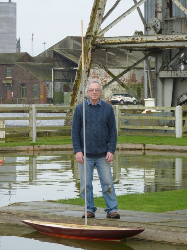
Here is a final picture of Serica in the pond with the mast fitted to give an idea of scale – big isn't it.
I think this is the first time the hull has been in the water in the 60 or so years since it was built and the really good news is there were no leaks – but it is bl**dy heavy to lift in and out of the water. The next job is to calculate the sail area, stand by for some tricky mathematics.
Gareth
Edited By Gareth Jones on 11/03/2017 20:01:59
12 March 2017 at 08:39 #70263 ashley needhamParticipant@ashleyneedham69188
Gareth that's a whopper and no mistake. Seeing it next to someone really makes the scale of it stand out,
I think you may need a bedsheet for the sails…..
Ashley
24 March 2017 at 20:13 #70427Gareth Jones
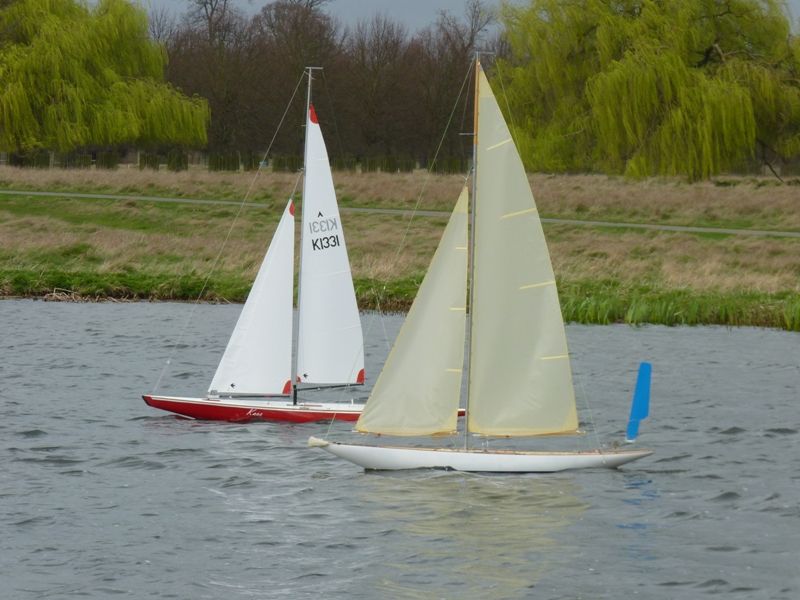
Participant@garethjones79649As Ashley mentioned recently we were invited to visit the hallowed portals of his shed last weekend. It was quite amazing, the way the boxes just kept on coming off the shelves, each one revealing a new and different model. The variety, ingenuity and build quality was excellent, including his latest foray into the world of vac-forming. We were sworn to secrecy so I can't show you any pictures inside the shed but I can show a couple from the other reason we went down south, to see some vintage A class yacht racing at Hampton Court. Here are a couple of photos of a pair of vane steered models beating their way along the pond in fresh breeze.
As you can see its a waders on job to launch and recover at the Rick pond so manhandling a 55 lb plus yacht while your feet are sinking and sliding on the mud is not for the fainthearted.
Gareth
24 March 2017 at 20:56 #70430Gareth Jones
Participant@garethjones79649The tricky calculations have now been completed for Serica and led to a tricky problem to solve. All the recognised racing yacht classes have a set of rules to ensure that all the yachts in the class are evenly matched. In some cases, such as Marbleheads the basic rules are quite simple, it has maximum hull length of 50 inches and a maximum sail area of 800 square inches, other than that pretty well anything goes and there is lots of scope for design development. Other classes such as the International One Metre are extremely prescriptive with virtually every aspect of the yacht hull and its rig defined in the rules. The A class falls somewhere in between and is based on a formula for a full sized 6 metre yacht scaled 1:6. This does not mean that the A class is one metre long, but when you feed in waterline length, sail area and displacement into the formula, you end up with a figure of 1 metre maximum, or if you work in imperial units 39.37 inches.
For the yacht to be competitive, you need to get as close to the class rule as possible, so when I fed in my waterline length, approx 59 inches, displacement, approx 1620 cubic inches based on a weight of 58.5 lbs, the formula indicates I can fit approximately. 1300 sq inches of sail area.
However the problem is there are also a number of other limitations which must be met or you suffer a penalty on the rating. For example draught must not exceed (waterline length x 0.16) + 3.5 inches. Any excess of draught must be multiplied by 3 and added to the rating and Serica was about 0.25 inches over the limit. Also the freeboard was under the limit by about 0.1 inch which also resulted in a penalty. These two parameters were going to cost Serica about 100 sq inches of sail. The challenge was to reduce the draught and increase the freeboard in order to avoid the penalties, but with the minimum reduction in displacement (effectively total weight) as reducing displacement would also cost me sail area.
I took Serica back to the pond and rechecked the waterline length, draught and freeboard with various amounts of ballast to give me weights of 54.5 lb, 56.5 lb and 58.5 lb.
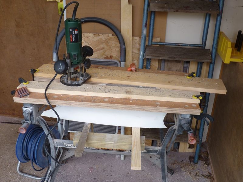
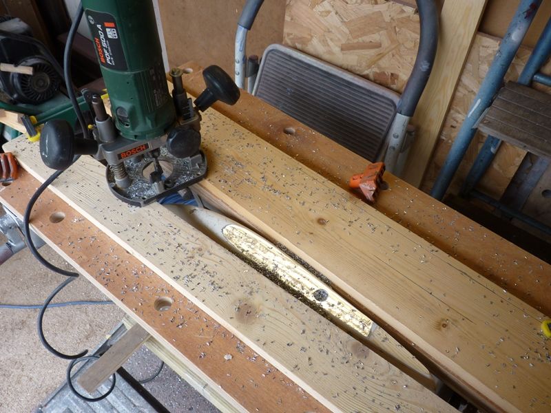
I worked out that if I removed about 0.2 inches from the bottom of the keel it would reduce the weight by about 1.4 lbs. The yacht would float about 0.1 inches higher because of the reduced weight and the draught would be reduced by 0.3 inches in total. This should be enough to avoid the penalties so I then had to come up with a neat way of removing the material from the bottom of the keel, a mixture of lead and wood. Sawing and filing would be tedious and messy. A milling machine would be ideal but I don't have one. However I have got a router and I reckoned that would be able to cope with machining away the lead provided the cuts were not too deep.
The first job was to remove the rear keel bolt or the router would end up hitting the retaining nut. A bit of heat from a blowlamp on the bottom softened the Araldite and it tapped out OK with a bit of persuasion from a light hammer and a hardwood drift. I managed to mount the keel in my workmate, using a couple of pieces of stout timber to support the weight on the cross bars underneath. The keel was clamped in the jaws and a couple of pieces of 1 inch thick timber provided a working base for the router.
The router made light work of the whole job and gave a very neat flat surface.
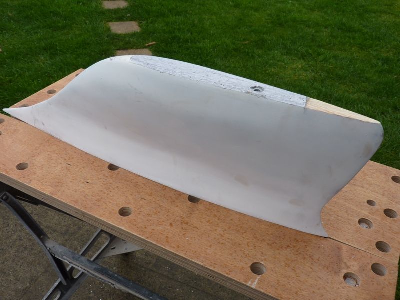
The corners have been rounded off, rear keel bolt refitted and the keel bolt hole refilled and the keel is now ready for a final coat of primer before getting a few coats of gloss white.
I have now started to make the mast, booms and deck fittings. The main part of the mast is 3/4 inch aluminium tube but the longest length available was 2 metres so the top section has been planed from a piece of pine dowel, tapering to approximately 1/2 inch at the top. The full length of the mast is approximately 8 feet. Today's job has been a start on the mast fittings to attach the shrouds and boom. However the first couple of attempts were not that successful and my initial attempt at silver soldering left something to be desired. However I am making progress and once I achieve something usable I will illustrate how it was done.
The sails have been ordered from Nylet so I have 8 weeks to get everything finished before they arrive, hopefully in time for the CADMA show at Doncaster where we will be hosting a vintage model yacht group stand and Serica will be centre stage.
Gareth
27 March 2017 at 07:21 #70455Banjoman
Participant@banjomanGareth,
This continues to be truly impressive in so many ways: the quality of the original build on the hull, the quality of your continuation of the build, the resulting beauty of the thing — and just the sheer size of it!!!
Mattias
Edited By Banjoman on 27/03/2017 07:21:47
2 April 2017 at 20:22 #70533Gareth Jones
Participant@garethjones79649This week has mainly been spent reducing bits of brass strip to scrap and filings. However I have now mastered the art of making the mast fittings and silver soldering the bits together so I have made some progress.
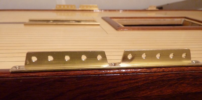
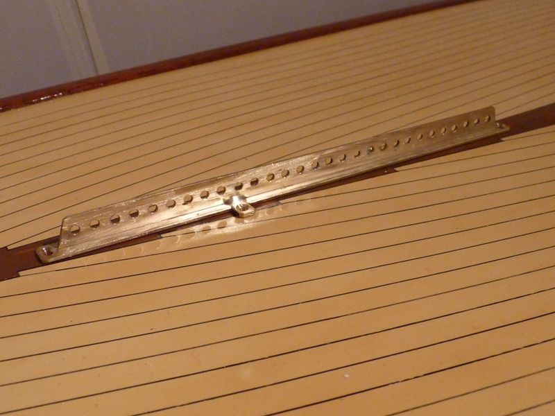
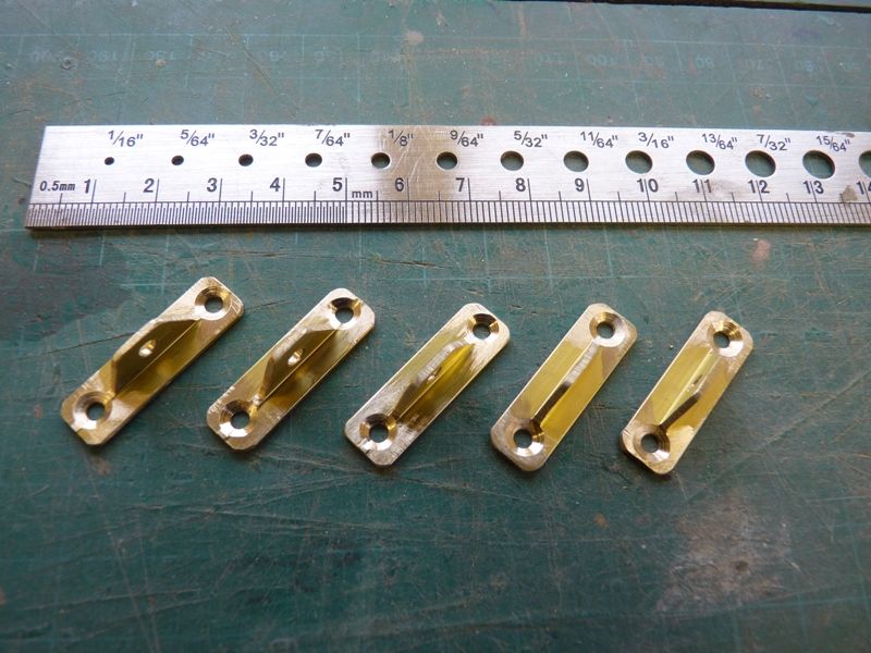
First the easy bit, although not quite as straightforward as I expected. I have spent a lot of time searching for some brass Tee section to make the shroud plates and jib rack. Unfortunately pretty well all that's available is either too small or too big. I did get some 6 mm x 6 mm from the 4D model shop some years ago but they don't stock it now and it would be a bit small for Serica. There is some 8 mm x 8 mm available from Modulor in Germany but the postage is expensive. Eventually I found some brass curtain track advertised. I thought it was an I section and big enough to cut in half to get 2 lengths of T section. 8mm x 8 mm. Unfortunately one end has an extra small T section on to to suspend it, so I could only use one side of the length, but there is plenty for Serica.
I have made the shroud plates as shown in the photo below
the jib rack
and assorted deck eyes
The next step is the mast fittings which is where all the scrap was created.
Gareth
2 April 2017 at 20:45 #70534Gareth Jones
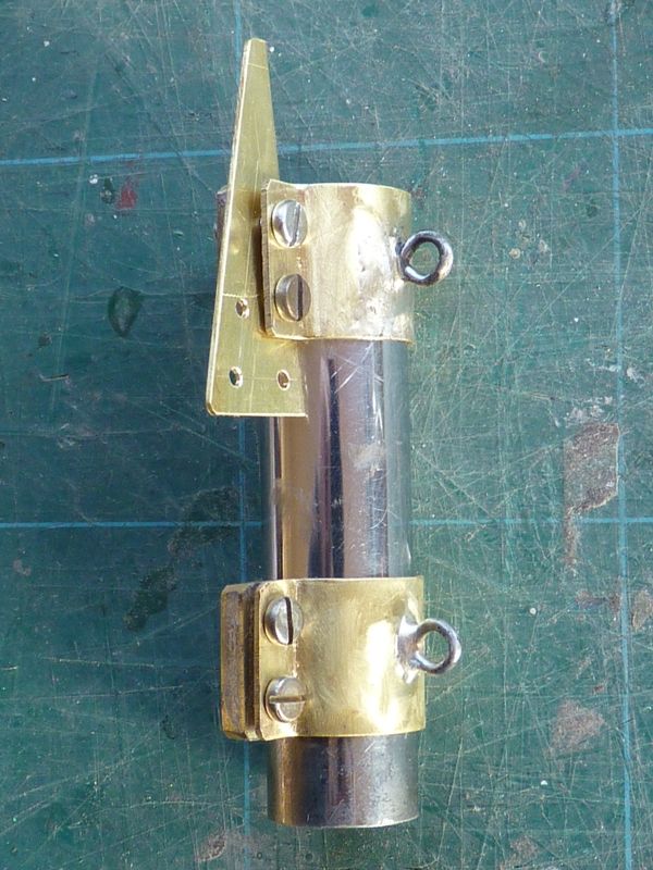
Participant@garethjones79649My first attempt at a mast fitting was one of the two straps that attach the boom and kicking strap. It was not a great success but served its purpose as practice and a prototype.
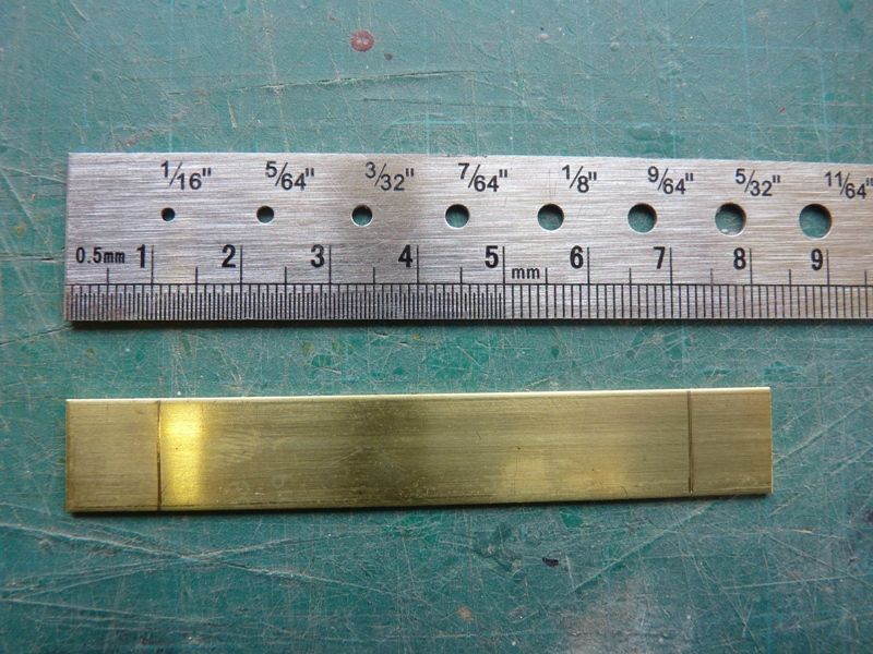
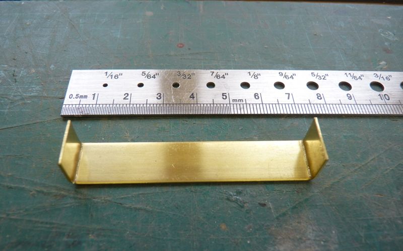
After several more practice pieces I evolved a process for making the bits the right size and rather more neatly. The first problem is to get the strap the right length and the distance between the two right angles correct. By trial and error I found that it was best to make the two flanges 10 mm to start with and the distance between them equal to the tube diameter plus 1 mm.
Here is an example marked out to fit on the 3/4 inch (19 mm) tube that the mast is made from.
The two ends are placed in a vice, in turn and bent up 90 degrees, with the line aligned along the top edge of the vice. Here is the result.
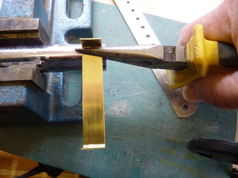
The trick is then to bend the strap around a tube, clamping it with pliers so that the bend starts right from each end, as shown below.
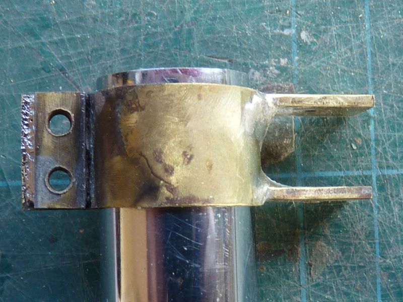
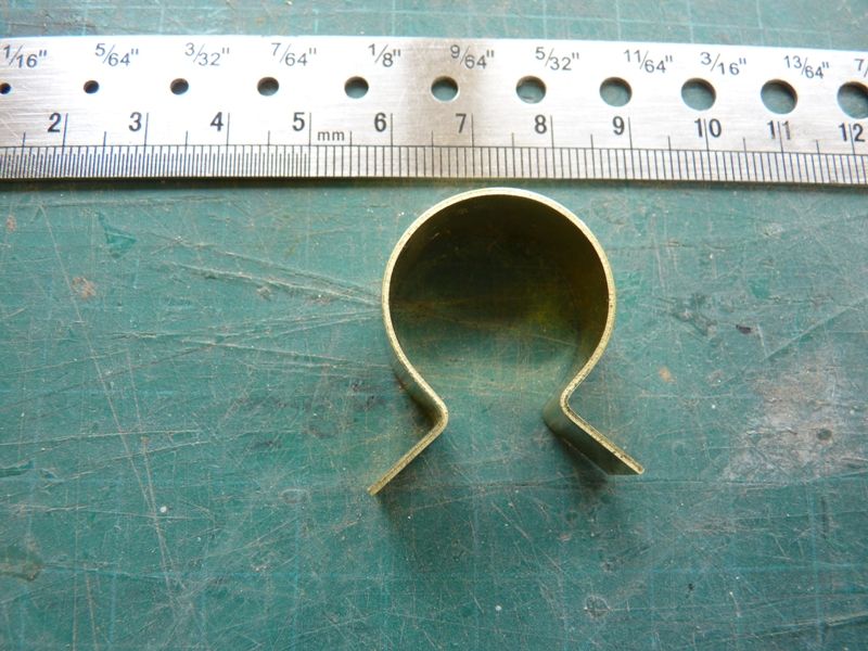
Each end is bent the same way and then the whole strap wrapped around the tube and clamped in a vice by the end flanges, pulling it tight round the tube, with the result as shown below.
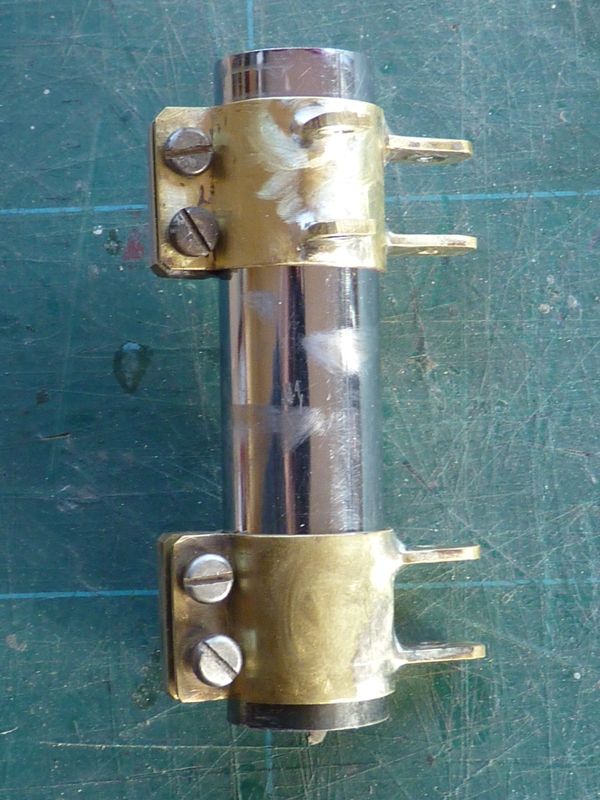
If everything works out ok the strap should just wrap around the mast with a gap of about 1 mm to allow it to be clamped by two 3 mm screws. I soldered a piece of 6 mm x 3 mm brass strip to one of the flanges, drilled and tapped it 3 mm to take the screws.
These formed the basis of all the mast fittings, some of which have eyes for shrouds and various other bits attached as shown here, working up from the bottom of the mast. Here are the mounts for the kicking strap and main boom. The two extra sets of lugs on the upper strap are to mount a spinnaker pole, not something I have ever done before but I thought I would make provision while I am at it. As you can see, my silver soldering has improved considerably.
The next pair up are the attachments for the lower shrouds and jib hoist.
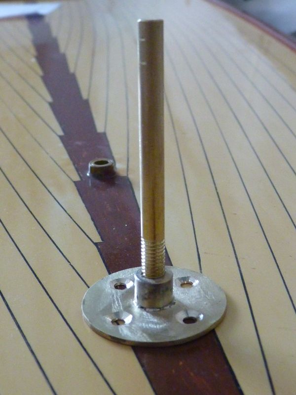
There are another 4 fittings to make but I decided to take a break at this point and do something different so I made the pintle mount for the vane gear. The pintle itself needs to be cut to length and the top pointed to locate in the bearing recess in the vane pivot. It will be retained in the mount by a locknut.
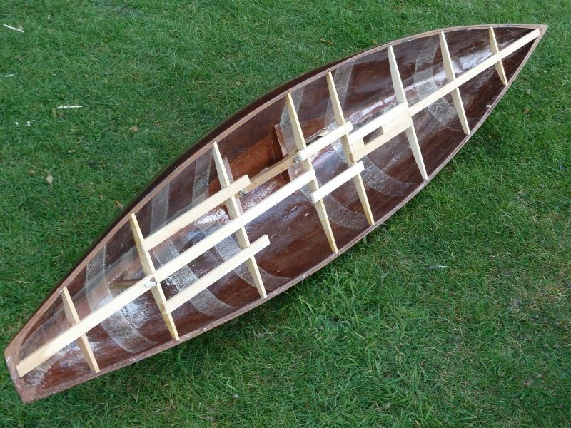
Finally, a picture courtesy of Anthony Warren of the Vintage Model Yacht Group showing the hull of Serica II after John Gale had finished carving the inner side of the hull, just prior to fitting the deck. Its a very useful picture as it gives me an indication of where all the hard points are under the deck.
3 April 2017 at 20:34 #70541Gareth Jones
Participant@garethjones79649First of all let me correct a silly mistake I made in the last posting. In the second paragraph I was taking about getting the length of the strap correct and I should have said the distance between the two marks for the right angle bends is the CIRCUMFERENCE of the mast + 1 mm, not the diameter +1 mm.
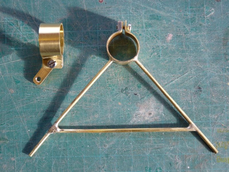
I have subsequently made a few more bits. Still working my way up the mast, here is the lower attachment for the upper set of shrouds and the spreader for the two upper shrouds. I will insert a couple of split pins in the ends of the tubes to hold the wires.
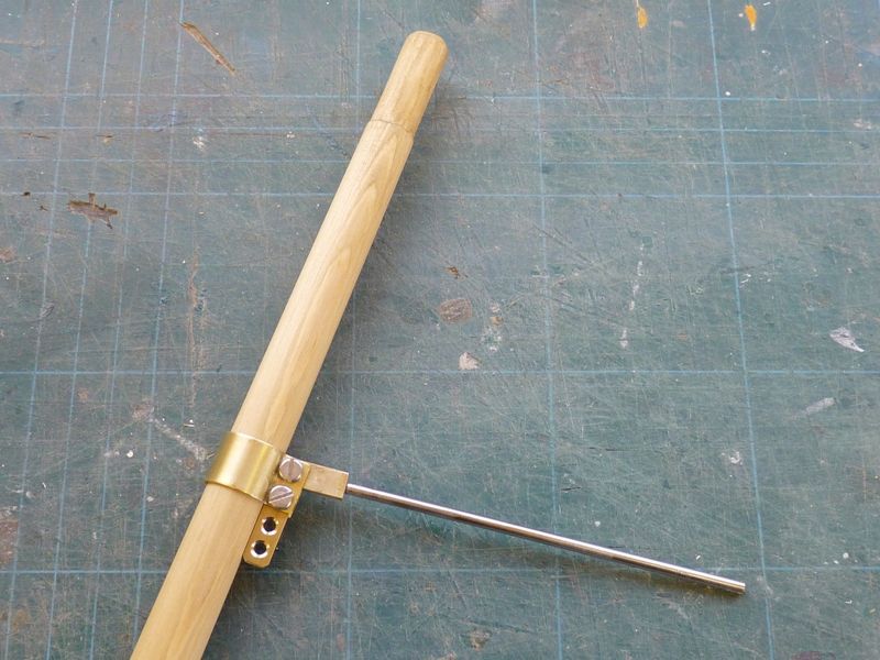
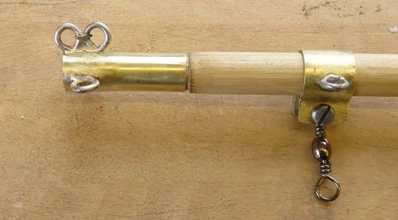
Next the backstay crane which attaches to the wooden extension on the top of the aluminium mast. There is a small hole drilled in the outer end of the stainless steel rod and a short sawcut to allow the backstay to be located in the crane. The top section of the backstay will be stranded wire, the rest of it will be Dyneema cord. The lug with two holes is the hoist point for the mainsail halyard.
The final mast fitting to make is the top strap with the eyes for the forestay and backstay but that is awaiting a bit of brass tube purchased on ebay for that purpose.
The main boom has been planed down to shape and size from a piece of pine dowel and, along with the top of the mast has been stained ready for varnishing.
The keel is finished and painted but is a rather glaring white in contrast to the hull which is a slightly warmer creamier colour. I plan to give the keel a couple of coats of varnish to try and get a better match.
The next job when the brass tube arrives is the top mast fitting and the main and jib boom fittings and then the kicking strap and deck horses. The final parts to make are the rudder lever and drive connection between the rudder and vane gear.. At that point, pretty well all the parts are made, and its a matter of putting it all together.
My target date is the northern VMYG meeting in Cleethorpes at the end of this month, but the initial sailing trials will probably be with a set of sails borrowed from one of Elizabeth's 10 raters, as I don't expect to get the pukka set until mid May. The 10 rater sails will be a bit smaller in area, but they are about the right height.
Will Serica II make it on to the water before Banjoman's Moonbeam I wonder?
Gareth.
3 April 2017 at 21:29 #70542Banjoman
Participant@banjomanGareth,
That is a case of absolutely stunning brass-mongery, that is! Really beautiful.
And yes: Serica II will most decidely make it onto the water before my Moonbeam – not only am I still only two thirds of the way down the jib luff with the bolt ropes (and thus have both main- and topsail still to do), but in the next couple of months we shall be moving house, with all that that entails in the form of planning, packing and unpacking plus of corse everything that'll go with the process of selling our current apartment.
The good thing about being in the process of doing the bolt ropes is of course that every five minutes that can be spared for such work are five minutes of actual work, and also it is work that can be done in front of the telly of an evening – my wife at her knitting and me stitching on rope to a sail … a picture of true domestic bliss, eh wot wot?!

Also and not least from a model boat building perspective this move'll be worth the effort, I think, when I contemplate the space that'll be available for my workshop after we've moved …
If all goes really well, I just might be able to finish Moonbeam before our removal, but it is far from certain, and I certainly wouldn't want to rush the job just to meet a self-imposed (and unnecessary) deadline.
Mattias
9 April 2017 at 16:15 #70583Gareth Jones
Participant@garethjones79649Mattias,
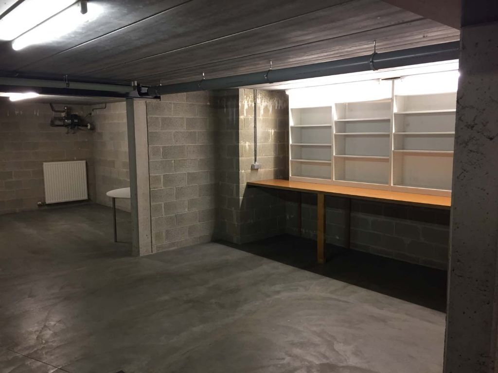
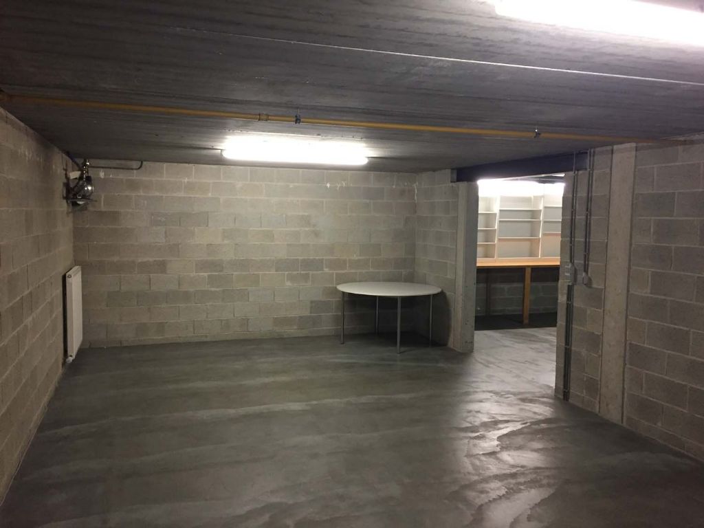
That looks a very useful sized space for a workshop, although it looks a bit dark at the moment. Is it located in a cellar or basement? It looks like you might need to add a few extra light fittings. Would you be able to do that yourself or do the building rules and regulations in Belgium prohibit that sort of thing. The electrical regulations were tightened up here some years ago so in the UK you are supposed to engage a competent qualified electrician to do that sort of thing nowadays. I dont think we have got as strict as some places. We have some friends who bought a flat in Switzerland and were very surprised to get a visit from a local council (or maybe canton) who had come round to check their fire extinguishers were within their inspection and maintenance time limits. Of course they also had to pay for the privilege of this service.
Serica has progressed a bit further, the main boom gooseneck and kicker strap are complete, as are ll the other fittings on the boom.
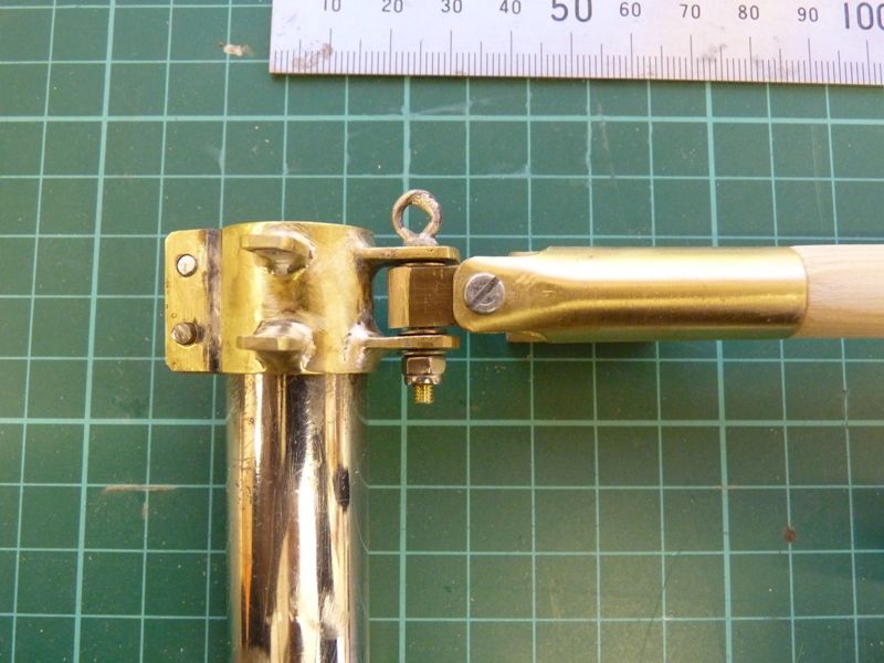
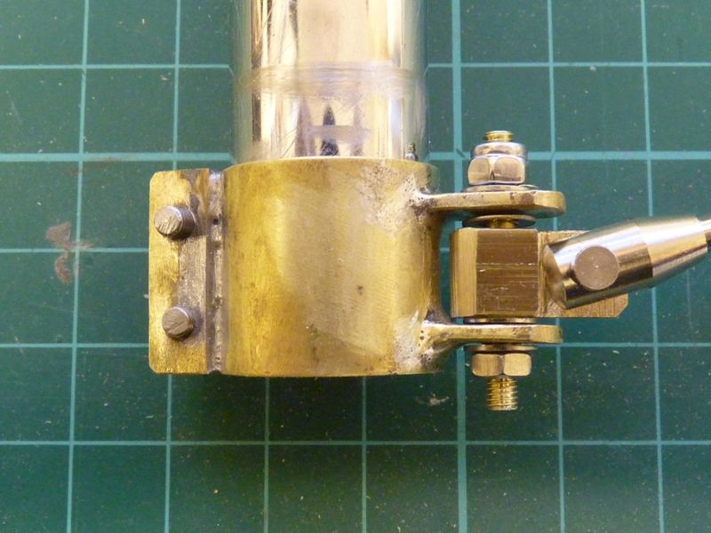
The top bearing is a piece of 3/8 inch square section brass bar drilled 3 mm in two planes.
The bottom bearing is similar but the brass bar had to be machined down to fit into the fork end of the turnbuckle adjuster.
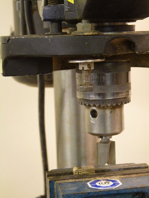
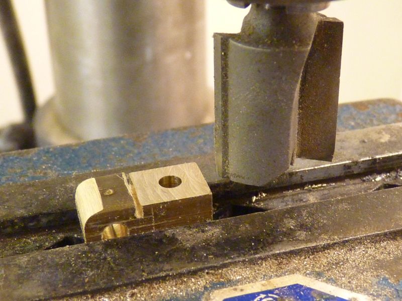
I have made one of these before for a large yacht and in that case I cut down the bar by sawing a piece out from each side and then filing it to size. This time I decided to have a go at machining it on my trusty pillar drill which was impersonating a milling machine for the day.. I clamped the block in a vice and used a router tool to mill away the surplus material. I made a saw cut first to give me a straight edge to cut up to. I fitted a bolt to the drill to act as a simple adjustable stop to set the depth of cut. The vice was slowly moved across the face of the cutter by hand, taking a few mm off each time.
I could only mill off a small section each time but it provided a neat and accurate way of reducing the thickness of the block. The process was repeated on the other side to give me a Tee section for the lower hinge.
Edited By Gareth Jones on 09/04/2017 16:17:31
9 April 2017 at 16:33 #70584Gareth Jones
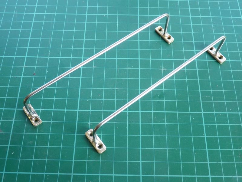
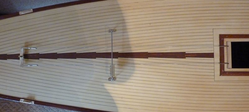
Participant@garethjones79649The next step was to make the deck horses from some 2.5 mm diameter stainless steel rod silver soldered into brass feet.
Since its a nice warm sunny day today I decided to start attaching the jib rack, shroud plates and some of the other fittings. The hull is now starting to look less bare.
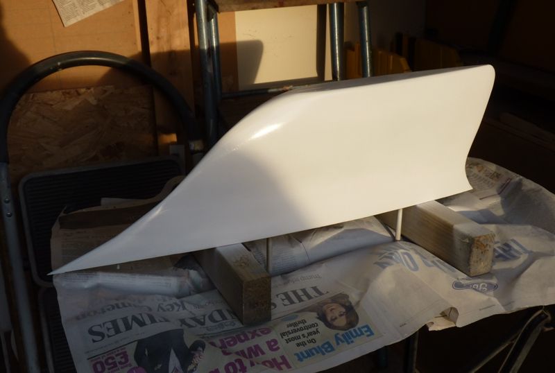
The new paint for the keel is still not a very good match for the rest of the hull as its still a bit too white. The latest attempt is Rover white diamond from Halfords which looked a closer match than our standard Appliance white. We could not see anything in the shop that looked a better match, based on the colours on the top of the tins, so I think I am going to leave it for the time being and hope it yellows with age.
The final picture shows there is also an ever so small kink at the point where the front of the keel meets the hull. I plan to have a look at this the next time I have the hull upside down and see whether I need to fair the two parts in together a bit better.
The next job will either be the jib and its fittings or the rudder/vane connecting mechanism, depending on how the fancy takes me next week. Sailing by the end of the month is still a possibility but my plans might be scuppered as there is now also a possibility I may be returning to work again – not that I want to work in the summer but needs must and it will be an interesting job.
Gareth
9 April 2017 at 21:26 #70588Bob Abell 2
Participant@bobabell2Hi Gareth
I like the sleek look of the hull, now that it's painted nicely and lined
Can we see a familier object alongside to get a feel for the size, please?
I also like your brass fittings, especially the Silver Soldered attachments
If you don't mind a suggestion, the complex fittings can be buffed up, using a wire brush
Bob
10 April 2017 at 09:38 #70590Banjoman
Participant@banjomanGareth,
It is, I think, a very useful space indeed: a total of 68 m2, not counting the garage part! And yes, it is a (window-less) basement, so I shall certainly have to improve the lighting. I doubt, though, that I'll do that in the form of new, permenantly fixed fittings, as it is a rented house, not one that we own. Instead I'll just put a sufficient amount of work lamps, e.g. these **LINK** of which I already have six in my current workshop. There are plenty of wall sockets available, and with LED lamps, the current drawn by each one is low enough that one needs not really worry about multiplying them.
I might also look at replacing the flourescents tubes in the existing fittings with LED ones.
Finally, I've also been thinking about getting a moveable lightsource of the type used by photographers to get really good light when painting larger pieces like boat hulls, but that'll be for later. As it is, I think the existing overhead fittings for general light together with work lamps for my work surfaces should be more than fine …
As for rules and regulations, I am not entirely sure what one is and is not allowed to do oneself here in Belgium, but given the amount and type of electrical installation material available in any DIY shop, taken together with the DIY gene strongly present in Belgian DNA, I suspect that one is still allowed a fairly free hand. However, any substantial change to an existing installation requires you to have it officially inspected. For my part, were the house ours to do with as we wanted, I would get a proper electrician in anyway for anything that required touching the fuse/distribution board. The potential consequences of a botched electricity job are so much worse than the cost of an electrician, I find …
Mattias
14 April 2017 at 11:32 #70625 Tony HadleyParticipant@tonyhadley
Gareth,
A very interesting build of this 'A' boat to a first class standard of workmanship. Hope the return to work doesn't cause any problems.
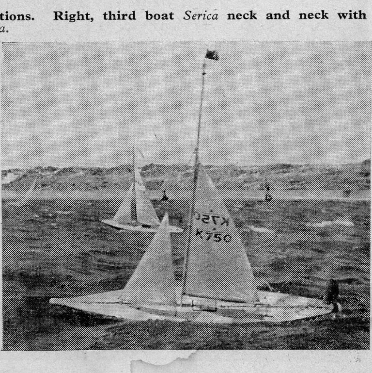
I came across a further photograph of the original Serica in the October 1957 Model Maker magazine. The yacht was racing at Fleetwood and finished in a very respectable third position. The scan isn't the best, it's not one of mine, came to me pre-scanned.
15 April 2017 at 20:43 #70631Gareth Jones
Participant@garethjones79649Hi Tony,
Thanks very much for another picture of the original Serica. It looks like a typical day at Fleetwood, strong winds and big waves and Serica heeled over despite wearing a very small suit of sails. Norman Hatfield obviously got around the country with his A class model, no mean task in the 1950's. I wonder whether he drove up from London or got the train. No motorways in those days so either would be a bit of a challenge with a 7 foot long 60 lb boat to shift.
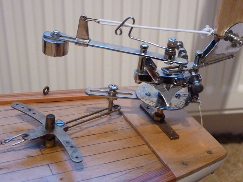
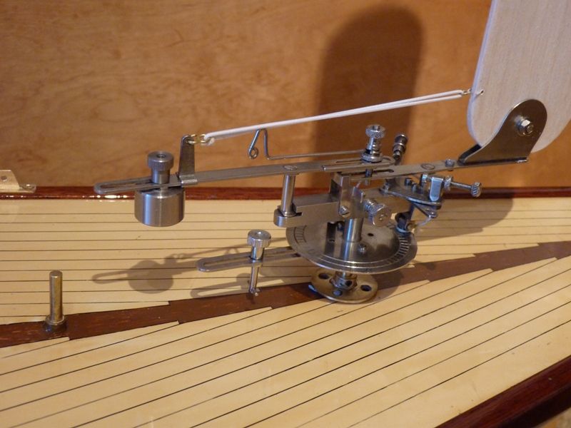
I spent a few hours last week working out where the vane pintle should be fitted. The vane I am planning to use for Serica II was bought from John Gale's daughter, along with the hull. It was made by Ken Corby, in stainless steel and is a fine example of the vane makers craft – it cost significantly more than the hull.
The vane is connected to the rudder by a pin which can be moved along a slot to vary the gear ratio between vane movement and rudder movement. He is a picture of a similar but smaller vane (not by Corby) on Elizabeth's Marblehead Pond Princess. In this case the vane, which came with the yacht, is mounted about 85 mm behind the rudder pivot.
According to Vic Smeed, in his book Model Yachting, the gear ratio should be variable from 1:1 to 3:1, i.e. in 'low gear' 3 degrees of vane deflection from neutral gives 1 degree of rudder movement in the opposite direction. On the Corby vane, with the pin closest to the vane, its effective radius about the vane pintle is 32 mm. For a 3:1 ratio that would mean the effective radius of the rudder lever would be 96 mm and so the pivot points of rudder and vane should be 128 mm apart. In the high 1:1 ratio, the radius of the vane is 64 mm and the rudder lever radius would also be 64 mm, gain making 128 mm apart, which is consistent and sensible.
Here is a picture of the Corby vane fitted to Serica, although the pintle is only held on with Blutack.
Having established the basic dimensions required I can now start to think about making the linkage that attaches to the rudder pivot. I suspect that the design dimension for the installation was actually 5 inches, bearing in mind the limited amount of metrication in the UK during the 1950's. Applying the same logic to Pond Princess's vane suggests the ideal position would really be 100 mm (4 inches) aft of the rudder but I suspect the original builder thought this might be a bit too close to the end of the hull and compromised.
There has been quite a bit of building also gone on over the last week but more of that later. At the moment I am banned from the workshop as its in paint shop mode for Elizabeth's current project.
Gareth
Edited By Gareth Jones on 15/04/2017 20:45:28
16 April 2017 at 07:48 #70633Bob Abell 2
Participant@bobabell2Hello Gareth and Elizabeth
i do like this contraption!……..It's amazingly complicated and really well made
A nice addition to your nicely restored yacht
Bob
16 April 2017 at 17:26 #70635Gareth Jones
Participant@garethjones79649Bob,
I have always been fascinated by mechanisms, it is probably a result of playing with Meccano from a very early age. Some of the most interesting jobs I worked on involved mechanisms of one sort or another, some very intricate and some apparently quite simple but often susceptible to subtle changes in geometry. Problems often only emerged when Fred retired after making the same bits for 20 years and Bert took over, not realising that Fred had never made it to the drawing but had his own subtle way of making it work, which he had never told anybody about.
I am not an expert on model yacht vane mechanisms but they are very clever devices. There are only about 3 or 4 different basic principles but dozens of variations on these themes and it can sometimes be very difficult to work out how they are set and used. They often have three different operating modes with adjustment on gearing and over centre spring tension, which means there is a long learning process and the only way to become proficient is by practice.
Ken Corby was acknowledged as one of the finest vane builders, basing all his models on the principle of the American Fisher gear, with his own improvements, in two different sizes. He built a total of 103 vane gears in the 1950's and 60's, the last three when he was 89 years old.
Gareth
Edited By Gareth Jones on 16/04/2017 17:28:12
16 April 2017 at 19:01 #70636Gareth Jones
Participant@garethjones79649This week I have managed to finish the jib boom, having made the 4 brass fittings that are attached to it. Here are the front two, including the attachment to the deck which will be via a fishing swivel.
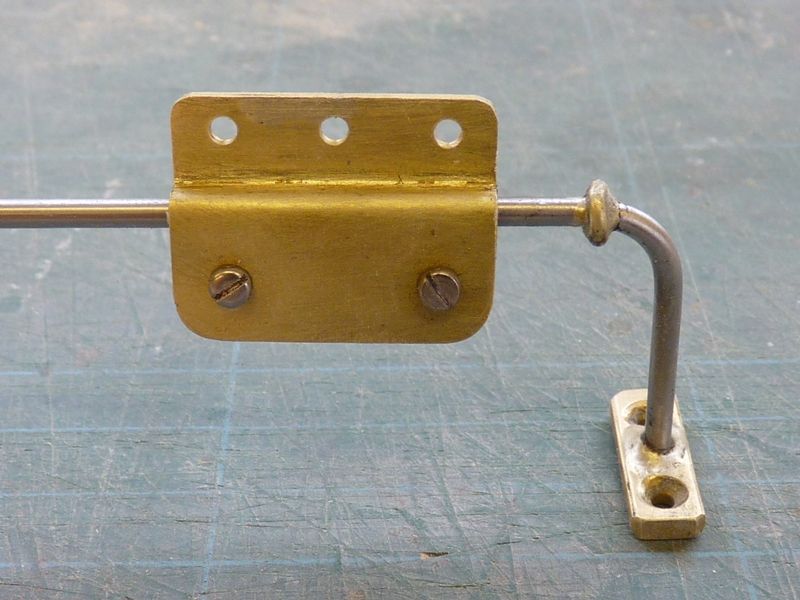
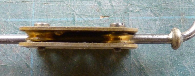
I have also made the travellers for the deck horses. These are made from 1/32 brass sheet, the most difficult bit being creating the 3 mm joggle to accommodate the pulleys that allow it to slide freely. Maybe I should invest in some sort of sheet metal folding and bending tools, rather than improvising with a vice, hammer and assorted bits of steel and aluminium strip. I also added some stops to the deck horses as I found the travellers could jam at the extreme ends. I should really have done this before adding the mounting feet. The stops are just coils of brass wire silver soldered on.
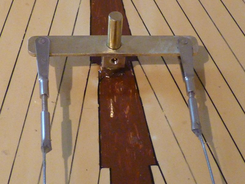
I have also finished the rudder controls. The rudder bar is a brass strip, with a boss silver soldered underneath. The boss has two tapped holes to take 3 mm grub screws that will allow the bar to be fastened to the rudder pivot post. The slotted lever that connects the rudder bar to the vane gear will be screwed to the top of the bar. I will also need to make provision for a spring attachment to centre the rudder when vane sailing. This is usually done with with a light spring or piece of elastic attached about 30 mm ahead of the rudder pivot, running forward to a deck eye, with some means of adjusting the tension, and thus centering force, in the spring.
The servo is mounted inside the main hatch and the whole system is quite discrete and can be removed completely when vane sailing.
Pretty well all the major parts are now made to allow the yacht to be sailed under radio control, so, if the weather is good I will start adding the standing rigging tomorrow. One of the problems of having a really big yacht is that there is nowhere indoors high enough to rig it properly.
Gareth
21 April 2017 at 20:04 #70720Gareth Jones
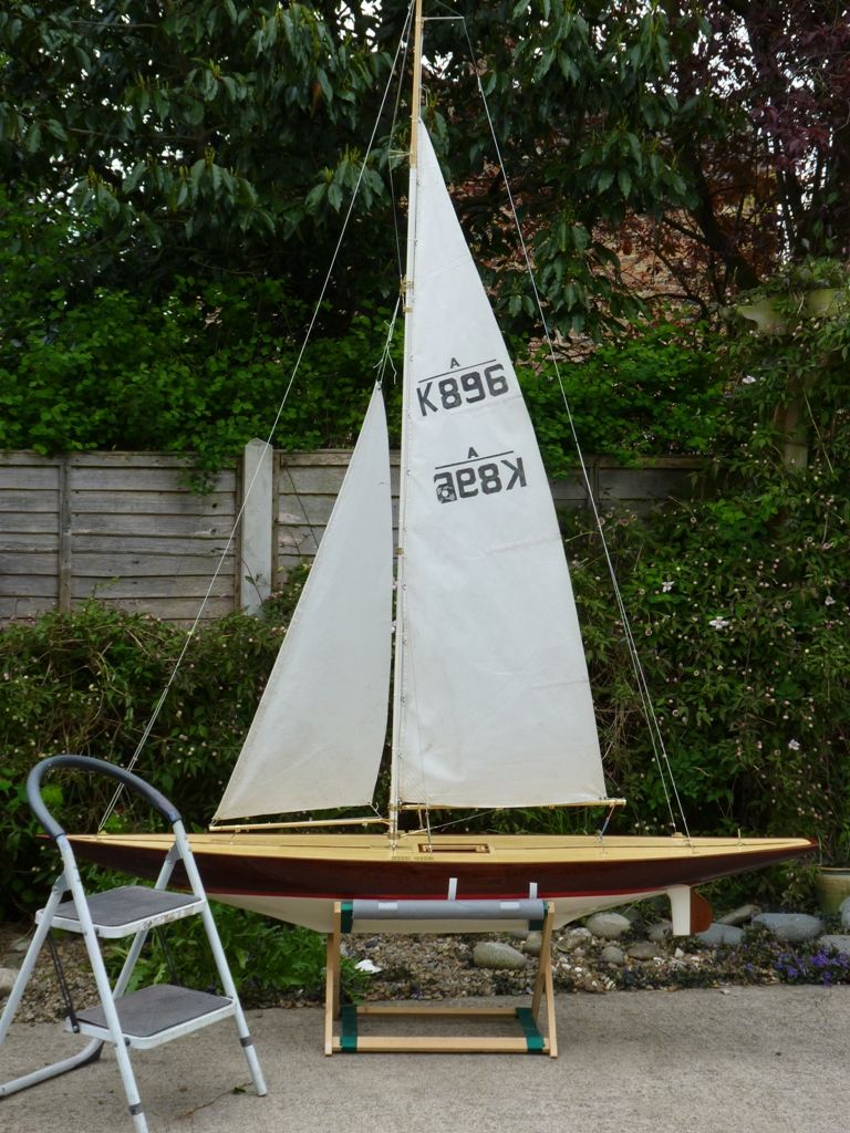
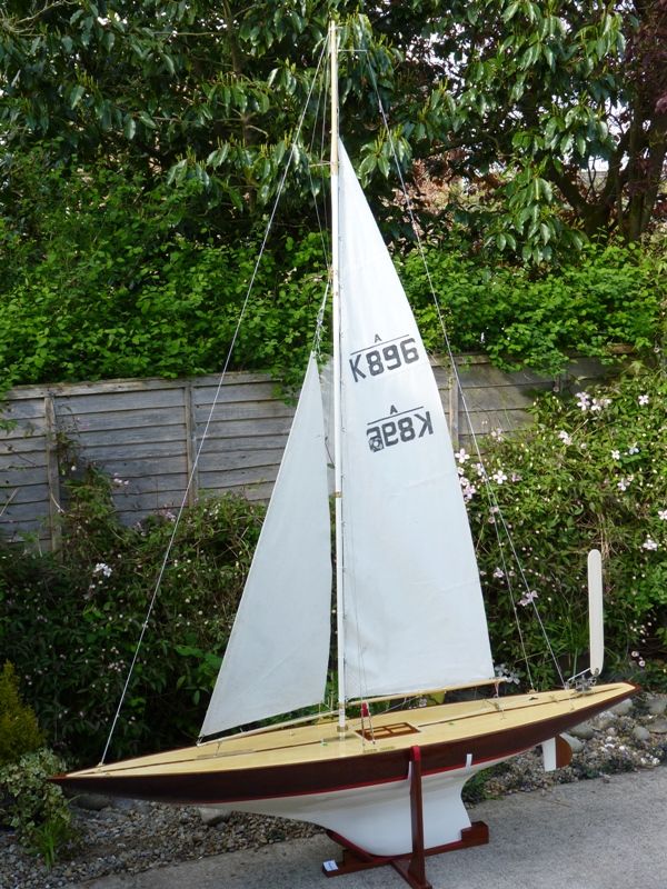
Participant@garethjones79649Here is a picture to give you an idea of the size Bob. The standing rigging is now pretty well complete and the temporary set of sails fitted. They are a very scruffy second suit from an unknown A class yacht. They came to us on an old 10 rater some years ago and are about 15% smaller than Serica's 'proper' sails but will do to aid rigging and for initial sailing trials. The next step is the winch installation and sail control sheets but that is held up by the weather at the moment as its a bit too windy to work outside with the booms and sails flapping around.
Gareth
21 April 2017 at 20:16 #70721Bob Abell 2
Participant@bobabell2Very nice, Gareth
I like curved back edges ( leeches?) very graceful
I was looking at a pro sail making article, the other day, and was interested in the method of making the pro sails with the Boom edge of the sail temporarily fixed to a curved mould, to give a permanent belly in the sail. Are you familiar with this method?
Bob
24 April 2017 at 19:56 #70763Gareth Jones
Participant@garethjones79649I have never tried making sails Bob, although I have heard of the use of 3D patterns to get an optimum shape. I think its one of those specialist subjects where you need a lot of experience and practice to get good results. Elizabeth has made quite a few sets of cotton sails but, apart from getting the warp and weft in the right direction that's about the limit of our expertise, and she would definitely not let me near her sewing machine.
Serica has progressed yet further over the last few days and is now ready to sail, under radio control, just waiting for some decent weather which looks like the end of this week at the earliest.
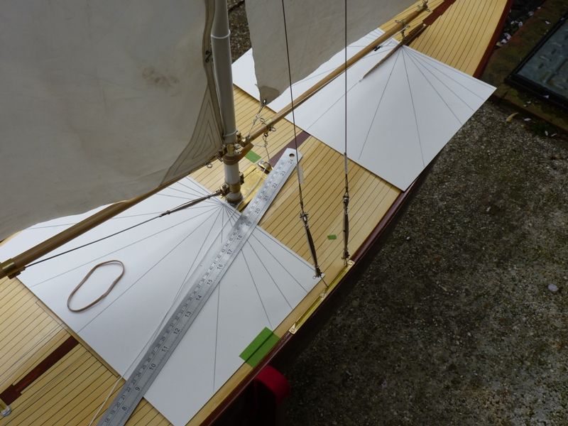
I spent most of Friday rigging the sailwinch and the sheets, which is always a bit of a juggling act. The winch itself was built on the bench sometime ago and, using a computer transmitter can be set up to give up to 425 mm linear travel on the control loop under the deck. Using basic geometry, this means that the attachments to the booms needs to be about 37 cm from their pivot points. Generally the jib is the shorter of the two booms and given the pivot point of the jib is about 20% back from the front end, 37 cm back from that would be right at the very aft end of the jib boom. Consequently I usually fix the jib attachment as far back as possible, blutack the deck eye in the required place and then see what travel of the jib I get, usually aiming for about 80-85 degrees either side of the centreline. It is necessary to adjust the sail winch travel on the transmitter to get the correct jib angles and in the case of Serica I found about 400 mm of winch travel was best. It then a matter of repeating the whole exercise on the main boom, but in this case, because it is much longer there is more scope for adjustment. I use a couple of pieces of cardboard marked at 10 and 20 degree intervals, and taped to the deck to give me a better idea of what the boom angles are. After several hours juggling the positions of the boom and deck attachments and the transmitter travel range adjustments I was eventually satisfied it was about as good as I could get. At that point there comes the crucial step of drilling the holes in the deck to fix the eye attachments under each boom for the sheets, not something you want to make a mistake with.
The deck eyes through which the sheets run need to allow the sheet to pass through and turn through 90 degrees with the minimum friction, even under high loads. The ones I have used are really too small so I have ordered some larger replacements and I will fit them when the proper sails arrive.
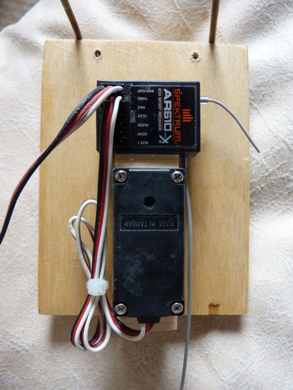
The radio receiver has been fitted up behind the rudder servo with one of the antennas blutacked to the underside of the deck and the other just sticking out sideways from the receiver.
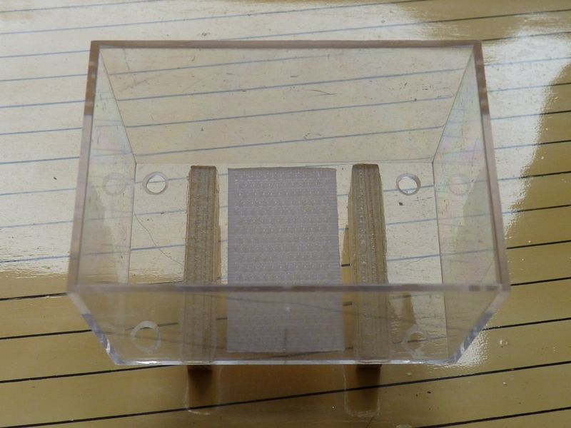
The receiver battery fits in a small perspex box that I happened to have stashed away because it might come in useful. The box straddles one of the floor beams on the bottom of the hull and is located by a couple of strips of timber and held in place with velcro. There is a hole in each corner to allow any water to drain out in the event that the main hatch leaks.
There are still some jobs to do on the vane mechanism and the sheets that control the sails when vane sailing. However these will have to wait till I get access to the workshop – still occupied by Elizabeths 10 rater restoration, or some calmer weather when I can work outside again. However Serica is looking good for sailing on Friday.
Gareth
Edited By Gareth Jones on 24/04/2017 19:57:16
24 April 2017 at 20:04 #70765Bob Abell 2
Participant@bobabell2Very nice Gareth…..Looks lovely
I`ve seen a class of model yacht, where they have the hull looking over size with unusually small sails, as the norm
They look very similar to your present set up
Any idea what class I`m referring too?
Bob
24 April 2017 at 20:28 #70768Gareth Jones
Participant@garethjones79649No idea Bob. Serica is an A class and the rating formula sets the relationship of displacement, sail area and waterline length. There are also constraints on sail height, draught and freeboard. Some of the more open classes such as Marbleheads and 10 Raters nowadays have very deep keels and are able to carry very high narrow sets of sails that sometime look a bit out of proportion to the length of the hull.
The set of sails fitted to Serica at present are only an interim suit for rigging and shakedown sailing. The 'proper' set has about 20% more area and is about 4 or 5 inches higher than the sails in the picture
Gareth
-
AuthorPosts
- Please log in to reply to this topic. Registering is free and easy using the links on the menu at the top of this page.
Code of conduct | Forum Help/FAQs
Latest Replies
Home › Forums › Sailing Models › Topics
-
- Topic
- Voices
- Posts
- Last Post
-
-
The new journey begins
1
2
3
Started by:
 mick east
in: Build Blogs
- 9
- 52
-
1 day, 1 hour ago
 mick east
-
New Website Forum – Discussion Topic
1
2
…
7
8
Started by:
 Colin Bishop
in: News and Feedback
- 20
- 183
-
1 day, 8 hours ago
 Colin Bishop
-
Tin Plate Clyde Puffer
1
2
…
7
8
Started by:
Len Morris 2 in: Scratch build
- 12
- 177
-
1 day, 9 hours ago
 Richard Simpson
-
Puffer advice
Started by:
 Alasdair Allan
in: All things floating
- 4
- 20
-
1 day, 10 hours ago
Len Morris 2
-
Todays Boating
1
2
…
200
201
Started by:
 ashley needham
in: All things floating
- 83
- 5,002
-
1 day, 19 hours ago
 ashley needham
-
Kempton steam open days incl boats
Started by:
 ashley needham
in: All things floating
- 2
- 7
-
1 day, 20 hours ago
 ashley needham
-
Purchasing Kits.
Started by:
Michael Cole 8 in: Building Kits
- 6
- 15
-
2 days, 18 hours ago
 ashley needham
-
Kempton Park Steam Engines
Started by:
 Colin Bishop
in: Shows and Events
- 1
- 1
-
3 days, 4 hours ago
 Colin Bishop
-
another Clyde Puffer
1
2
Started by:
mmcp42 in: Scratch build
- 7
- 45
-
3 days, 6 hours ago
mmcp42
-
Wanderer III
Started by:
grich101 in: Scratch build
- 4
- 5
-
5 days, 16 hours ago
 Ray Wood 3
-
Two more of my old models gone
Started by:
Bob Wilson in: Static modelling
- 1
- 1
-
6 days, 3 hours ago
Bob Wilson
-
Two more of my old models gone
Started by:
Bob Wilson in: Static modelling
- 1
- 1
-
6 days, 3 hours ago
Bob Wilson
-
May 2024 issue not in the archive?
Started by:
mmcp42 in: News and Feedback
- 2
- 5
-
1 week, 2 days ago
mmcp42
-
My Clyde Puffer
1
2
…
9
10
Started by:
James Hill 5 in: Scratch build
- 17
- 241
-
1 week, 3 days ago
Len Morris 2
-
Wild Duck meets Eventide
1
2
Started by:
Tim Rowe in: Scratch build
- 5
- 30
-
1 week, 4 days ago
 Tim Rowe 1
-
Ben Ain
1
2
3
4
Started by:
 Richard Simpson
in: Steam powered models
- 8
- 99
-
1 week, 4 days ago
 Richard Simpson
-
getting the boat to pond
Started by:
 Alasdair Allan
in: All things floating
- 3
- 8
-
2 weeks, 1 day ago
 ashley needham
-
MFA Motors ceasing business
Started by:
 Colin Bishop
in: All things floating
- 3
- 3
-
2 weeks, 5 days ago
 ashley needham
-
HMS Glory
Started by:
 Colin Miller
in: Build Blogs
- 4
- 18
-
2 weeks, 6 days ago
 Colin Miller
-
ss Miltiades 1901
Started by:
 Colin Bishop
in: Scratch build
- 2
- 3
-
3 weeks ago
 Colin Bishop
-
Amati j class yacht kit
Started by:
 ashley needham
in: Buy/Sell or Trade
- 4
- 6
-
3 weeks, 1 day ago
 ashley needham
-
North West Model Shipwrights Society
Started by:
Bob Wilson in: Club News
- 6
- 17
-
3 weeks, 3 days ago
Bob Wilson
-
ballasting a paddle steamer
Started by:
 Alasdair Allan
in: All things floating
- 5
- 17
-
4 weeks ago
 Colin Bishop
-
Aerokits pt boat bulkhead plans wanted
Started by:
Roo Hawkins 1 in: All things floating
- 1
- 1
-
4 weeks ago
Roo Hawkins 1
-
building a display case
Started by:
 Alasdair Allan
in: All things floating
- 5
- 17
-
1 month ago
 Colin Bishop
-
The new journey begins
1
2
3
-


