Spritsail barge Veronica

Advert

Spritsail barge Veronica

Home Forums Scratch build Spritsail barge Veronica

  • This topic is empty.
Viewing 25 posts - 26 through 50 (of 72 total)
  • Author
    Posts
  • #53138
    Dave Milbourn
    Participant
      @davemilbourn48782

      Geoff
      I'm currently building a plank-on-frame Dumas kit (of which the least said the better) and the instructions say to cover the outside of the hull with 2" wide parcel tape while you brush polyester resin inside and swill it all round the hull to waterproof it. The resin will run into any gaps between the planks and set up hard. The tape is, of course, there to stop the resin getting onto the outer surface and should be removed before you apply the P38 etc. I subsequently used Z-Poxy epoxy resin and cloth to finish and had no conflicts between that and the polyester. If you're at all concerned then use epoxy for the inside as well.
      Dave M

      Advert
      #53139
      Geoff Sleath
      Participant
        @geoffsleath41411

        What a good idea, Dave. I'll do that. I bought a few cheap paint brushes in Poundland yesterday for once only use with resin. Thanks.

        Geoff

        #53140
        Kimosubby Shipyards
        Participant
          @kimosubbyshipyards

          Geoff,

          FYI the original barges were planked from the bottom up, between each plank a layer of reindeer hair and tar was used, and the weight of the plank squeezed this out forming good seals. When new planking was required it was added to the outside of the original, so the barges actually got beamier.

          DM's idea is good, my Lady Daphne has exactly as suggested, a good wash inside of polyester resin (without any matting).

          The hulls are always painted, so any fillings etc can be covered over.

          Kim

          #53141
          Geoff Sleath
          Participant
            @geoffsleath41411

            Kim

            Reindeer hair! What a strange choice to make for boats built in SE England rather than northern Scandinavia …or perhaps it was saved from where Santa's reindeer brushed against Maldon's rooftops I think I'll use epoxy resin (I never have any polyester in stock) and leave animal hair to the real scale enthusiasts.

            Not sure what to do next once the hull shell is complete. I may move onto the mast and rig generally as the open hull will give maximum access for the sail winches. Things I need to buy next weekend at Warwick.

            Although the rudder servo mounts will be fairly easy to do as well. Not sure why there are two push rods acting as a closed loop system to the rudder tiller. Unless the tiller and the servo arm holes are exactly the same distance apart making a perfect parallelogram things could seize up. The closed loop controls I've done before have always been with thin Bowden cable and the none pulling cable can be slack. I only used one push rod on my 1 metre yacht.

            Geoff

            #53143
            shipwright
            Participant
              @shipwright

              Geoff

              If you use a rudder arm with 2 clevises and threaded 2mm ss rod it is easy to adjust the rod lengths. The non threaded end of the rod is bent into a right angle and secured with a collar/grubscrew. See photo :

              photo_of_rudder_arm_&_clevis.jpg

              #53145
              Geoff Sleath
              Participant
                @geoffsleath41411

                The rod length isn't a problem as they're easily adjusted. The exact equidistance of the holes in the tiller arm and the servo horn is because if the set up isn't a perfect paralellogram (or, at least have enough slop in the connections) it can't turn and can cause the servo to stall. I just don't see the point in having 2 push rods.

                btw you can use Z bends at the non-adjustable end rather than collets. There are also plastic gizmos you can use rather than a Z bend – SLEC make/sell them.

                Geoff

                #53147
                Dave Milbourn
                Participant
                  @davemilbourn48782

                  I'm 100% with you there, Geoff, but we're fighting a losing battle against those folk who believe that a model boat rudder can produce enough force to buckle a 2mm steel rod simply by compressing it end-to-end. Nonsense. I'm presently investigating the second statement about the system binding up as you increase rotation. I'm not so sure that it matters for useable angles e.g. up to 30° each way although I think it does at extremes. I shall report back!

                  DM

                  Edited By Dave Milbourn on 29/10/2014 19:29:58

                  #53149
                  Paul T
                  Participant
                    @pault84577

                    Twin push rods are an engineering 'correct practice' as they equalise the forces being exerted on the servo……. as to whether or not they are actually required would depend upon the size of the rudder, the length of the push rods and the power output of the servo.

                    #53150
                    Dave Milbourn
                    Participant
                      @davemilbourn48782

                      Paul/Geoff
                      I agree, with the caveat that the distance between the pushrods must be identical at both the tiller and the servo disc AND the holes are not staggered as in the picture shown. My CAD drawings show that up to 30° rotation each way there is no practical effect of having different "widths across each, but that this becomes more significant as the angle increases. I'm trying to get these drawings into a presentable form to show here. Bear with me. Ref the parameters, you forgot the density of the water………..which has a happy tendency to move out of the way quite readily – hence propellers.
                      Dave M

                      #53151
                      Paul T
                      Participant
                        @pault84577

                        Dave

                        I didn't want to over complicate matters by delving into water density, water temperature, cavitation and the forces exerted on the rudder post by the changing propeller thrust. Then there are the additional problems when the model is going astern.

                        Paul

                        #53152
                        Dave Milbourn
                        Participant
                          @davemilbourn48782

                          Paul

                          Just pulling your leg.

                          My point is that water is a pretty forgiving medium, certainly at the speeds that Geoff's model is likely to achieve. I have NEVER fitted twin pushrods in any of my models and have never had any evidence that there was any distortion of the ones which I did fit, certainly not to the extent that it was either visible or had any effect on the steering of the model. A belt-and-braces approach is all very well – and may be "good engineering practice" – but you don't need either for your Speedos.

                          Ref my earlier point about the geometry, here are the drawings. The top one shows the system at neutral, with 40mm between the pushrods at the servo disc and 60mm at the tiller. Note that the holes on each are all in a straight line.
                          The second diagram shows the same system with a 30° rotation at the servo disc. The pushrods are drawn exactly the same length throughout. You'll see that there is no discernable strain in the system, as the axis point of the tiller remains in the same place i.e. the pushrods aren't trying to pull it towards the servo (or if they are then it's with very little force). The unlabelled angle at the tiller is about 19.2° incidentally.
                          In the third and fourth drawings however the angle increases to 60° and finally 85° and you can see that the axis point of the rotated tiller arm wants to drift away from its neutral position towards the servo. In a model the servo would be trying to rip the tiller arm off; bend it, or bend the rudder tube. If you introduce angles like that in the earlier photo of the tiller arm then things get worse. The effect would be to bind or jam up the whole shebang.

                          steering geometry.jpg

                          I hope that's clear. At the end of the day this is a bit like arguing about the best car. Everyone will have a pretty entrenched position. I suspect that the belt-and-braces/good-practice chaps will continue to fit dual push/pull rods and us old aeromodellers will continue spend less on threaded rods and clevises. To each his own, or suit yourselves.

                          Dave M

                          Edited By Dave Milbourn on 29/10/2014 20:26:55

                          #53154
                          Geoff Sleath
                          Participant
                            @geoffsleath41411

                            There have been seemingly endless discussions about closed loop controls in the mode aircraft forums. I'm quite proud to have won the argument with one contributor who is usually (always!) right on technical matters. If I use a closed loop rudder control it will probably be with Bowden cable connections. It works on very large scale aeroplanes so a 1 metre barge should cope. Full scale Tiger Moths are festooned with closed loop controls Always fun, though.

                            I assume a Futaba 148 or similar will be more than sufficient for the rudder. I have a box full, mostly good used from models that have climbed to the hangar in the sky … or more accurately the hell beneath the airfield

                            Now my barge is sitting on the bench looking like it's ready to be posted somewhere so wrapped up in parcel tape. The inside is well coated with epoxy so I'll see what the morning brings.

                            Geoff

                            #53179
                            Amy jane September
                            Participant
                              @amyjaneseptember49770

                              My 5', 30lb speed boat uses a single 2mm wire push rod on a standard servo, with no issues what so ever.

                              #53186
                              Geoff Sleath
                              Participant
                                @geoffsleath41411

                                That's good to know, Amy Jane, though I think if it had been my speed boat I might have used a beefier servo and a 3mm connection. I do tend to over-servo my aeroplanes, particularly those getting towards the lower official large model weight limit of 7kg and 3mm push rods are so reassuring.

                                Spent the day making a main mast from a length of 15×15 pine bought from B&Q. Quite satisfying planing and sanding it to shape with a 12×12 square at the step, tapering to 10mm round at the top. It's amazing how round it's possible to get it just by sandpaper without any mechanical aids.

                                Studying the rig drawings to see where all the bits of string re supposed to go. Peter Simmonds in the DVD uses 2 sail winches. 1 for the main sheet and the other for the sprit vang to control sail twist. Trying to work out how the vang can be adjusted without adjusting sprit uphaul (if that's what it's called). Apparently the jib isn't adjusted on a barge. Not sure about the staysail or mizzen sail, though. I'm very familiar with Bermudan rigs but sprit sails seem a lot more complicated.

                                The hull epoxy and parcel tape method worked a treat, too. I just felt like a change today and did something different from the hull.

                                Geoff

                                #53188
                                Amy jane September
                                Participant
                                  @amyjaneseptember49770

                                  There is something about getting a nice, tapered spar out of a solid block of timber, seeing it come to life. Making full sized spars, oars and paddles is even more satisfying!

                                  Sounds like your build is really cracking along!

                                  #53376
                                  Geoff Sleath
                                  Participant
                                    @geoffsleath41411

                                    Thanks, Amy-Jane. In case anyone should think the 'cracking along' has petered out a little here's a bit more progress. I've been finishing off the hull shell and covering it with lightweight glass cloth (30gms/metre square) and West epoxy to give it better strength and resistance to knocks. It's slow job, as West is very slow curing but very hard once it is. I also did it in 4 separate sections. Took a long elapsed time and wasn't really very interesting to report on.

                                    Here's the glassed hull as it is now.

                                    veronica hull 6.jpg

                                    veronica hull 7.jpg

                                    veronica hull 8.jpg

                                    That's as far as I'm going with the finishing for while. Once the rest of the hull and deck are completed it will be sprayed. Before spraying I'll indicate the planking with 0.4mm masking tape at the edge of each plank and then after a coat of high fill primer the tape will be removed leaving a gap between each plank. It'll take almost 40 metres of tape! Approximately 20 planks per side and an 1100mm water-line length will make for a fairly tedious task but I hope it will be worth it when I spray the final coat of paint. It should look like a fully planked traditional working boat hull.

                                    I had a crack at the rudder whilst waiting for the West to cure. I roughly cut out 3 pieces of 3mm plywood to the right shape:

                                    rudder 1.jpg

                                    Then cut out a notch in the middle piece to take the Perspex rudder extension that's needed to make he model steer like the full-size

                                    rudder 2.jpg

                                    I'm not entirely satisfied with the final result but I think it may be OK once it's finished. The strapping is from shim copper I had in my scrap drawer and he post is 9mm square Beech (I think) sold as engine bearers. The black lines are black ball pen which look awful. However, they will be covered with 0.4m tape and the planking will be simulated like the hull planking. I'm hoping the copper shim will be thick enough to show through the paint.

                                    rudder 3.jpg

                                    The rudder hinge will be 3 Robart pin hinges rather than traditional gudgeon and pintles for convenience. The will hardly be seen. In any case the lower 2 are shielded by a rubber strip in the full size to reduce drag apparently.

                                    Geoff

                                    #53378
                                    Ray Wood 3
                                    Participant
                                      @raywood3

                                      Hi Geoff

                                      She is looking good, the Robart hinges should do the trick ! I like a bit of cross-fertilization from the aeroplane world.

                                      I once used a Micro Mold clevice to drive a mechanical lubricator on 3.5" steam engine I built, caused a stir at my model engineering club

                                      Barrie Stevens the editor of MMI tells me he is meeting Peter Simmonds who did the DVD at the Warwick show to see what has happened with the bulkhead shapes, it appears they have published a early version which needs revision.

                                      KR

                                      Ray

                                      #53380
                                      Geoff Sleath
                                      Participant
                                        @geoffsleath41411

                                        Thanks for that, Ray. I intend to go to the Warwick show on the Saturday, probably so I may get to meet Peter Simmonds.

                                        I still waiting to hear what Traplet intend to do as compensation for the faulty components that caused me so much angst. I had to wait for my wood-pack because, I was told, they had been popular and were out of stock. So somewhere there are other builders who will have the same problems I did, but perhaps haven't started yet. I started building almost immediately, only delaying a little studying the plans and watching the DVD. I've made a copy of the DVD because I was afraid of wearing it out, I'm watching it so often At least, it wasn't a mistake I made which is usually the case.

                                        I can't think it was an early version of the drawing because it's so wrong. It's just a faulty version and poor quality control.

                                        To be quite honest, I would have thought the Micro Mould clevis was an obvious thing to use. What would your model engineering friends have used? Though, I must admit, I'd have used a metal clevis, which may have met with more approval

                                        Geoff

                                        #53531
                                        Geoff Sleath
                                        Participant
                                          @geoffsleath41411

                                          I visited the Warwick show on Saturday and met Peter Simmonds who stars in the DVD of the Veronica build. He was very helpful and I learned a lot from him about how to rig the model and what the sail controls should do. I took a load of photographs which will help.

                                          I also met Kim and admired his superb model barges. I'm not sure whether I was inspired or discouraged at the high standards he sets. Time will tell. Thanks Kim Also had a quick word with Dave Milbourn in a brief respite from selling stuff and advising customers on the Component Shop stand.

                                          On the Traplet stand I had a word with the editor of MMI about my problems with the woodpack. It seems someone got files mixed up and an old version was used to cut the batch of parts I received. It's still being sorted out and new woodpacks are on hold until it is. I think any future potential Veronica builders can be confident of receiving accurate components and drawing.

                                          I asked for a refund of my woodpack costs. Traplet have gone further and refunded the total cost of drawings, DVD and woodpack and I'm completely satisfied with their treatment of my complaint. After all, anyone who never made a mistake never made anything as I know from very personal experience! Traplet came clean and admitted their error and have sorted it out.

                                          Geoff

                                          #53553
                                          Kimosubby Shipyards
                                          Participant
                                            @kimosubbyshipyards

                                            Hi Geoff,

                                            Nice to have met you and many thanks for your kind words re me, and Peter etc. As you saw, though their construction appears simple, there are some peculiar ways that the old barge builders used. We, Richard Chesney, Peter and myself are so glad that you sorted every thing out with Traplet to your satisfaction. It does no good to any reputations if a known error goes unsorted and causes frustration and bad will to the detriment of the hobby. I'm sure all will come good very soon, as there is now a waiting list for kits.

                                            The diorama was something else too, though you don't mention it. I've put some images on another thread to do with the show, so look there to see what I'm on about, any who read this.

                                            Geoff, great to meet up, putting faces to forum members is quite exciting, preconception of what "kimosubby" looks like etc. Oh, that's also blown, thanks to Colin!

                                            Aye, Kim [keep the thread winding along!]

                                            #53781
                                            Geoff Sleath
                                            Participant
                                              @geoffsleath41411

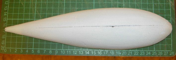
                                              I've been doing a bit and thinking a lot. I've installed the two winches and the rudder servo. I've also made the 'cheat' fin and a half pattern for the lead bulb in blue foam. It's the lead bulb that's causing me a little headache.

                                              I've made the half pattern from the drawing. It's roughly an aero-dynamic (hydro-dynamic?) shape with a length of 28 cms and a main chord of 7cms. I assume it's circular in section though it isn't stated.

                                              So: I've estimated the average chord is 5cms, hence the volume is given by

                                              pi r^2 x length = 3.142 x 2.5 x 2.5 x 28 = 550 cc. ie a cylinder of radius 2.5cm and length of 28cm

                                              lead has a density of 11.34 gms/cc according to Wikipaedia so the weight of a lead cylinder that size is

                                              11.34 x 550 grams = 6,237 = 6.237 kg = 13.27 lbs!! approx.

                                              That's a lot of lead! Can someone please tell me what I'm doing wrong? Or is the drawing wrong – again?

                                              Here are the fin components. There's only an outline of the fin on the drawing with no clue as to how to make it. I made outlines of the top and bottom of the fin in 3mm ply with a slot at top and bottom to take the 6mm fin blade aft of the 6mm threaded rod. The narrower 6mm part extends downwards to help to locate the lead bulb.
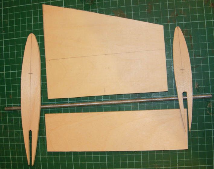
                                              fin 1.jpg

                                              Here are the components being glued together with waterproof PVA. This forms the skeleton of the fin.
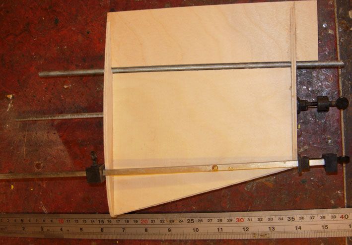
                                              fin 2.jpg

                                              The aerofoil shape is done by glueing in slabs of blue foam and sanding to shape using the top and bottom plywood shapes as guides. Blue foam is quite dense and sands well. It's heavier than the more common packing type foam but that's not a problem in a fin. The locating tongue is to the right.
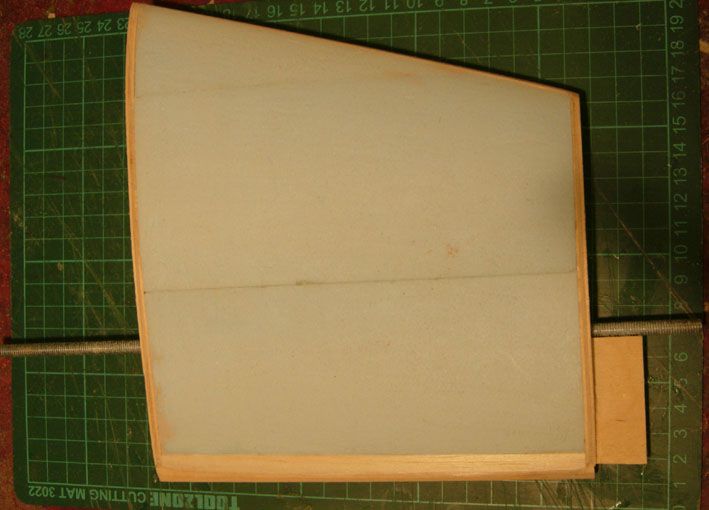
                                              fin 3.jpg

                                              Now we come to the slightly problematical bulb keel. Here's the blue foam half pattern I intend using to make a mold to cast the lead bulb. It's quite accurate to the drawing, though not perfect – after all I made it

                                              fin 4.jpg

                                              I'd be grateful for any advice on how to make the molds. I've thought of fibreglass (probably cheap polyester resin) or perhaps even plaster of Paris. An easier route could be sand but I've never tried that and I imagine the molten lead just running through the grains of sand.

                                              Mostly I'd be grateful if someone could point out the error in my estimate of the keel weight.

                                              Geoff

                                              #53782
                                              Geoff Sleath
                                              Participant
                                                @geoffsleath41411

                                                I've just applied good old Archemedes bath method and measured the volume of the bulb as 680ccs ie even more than my estimate!

                                                I used 2 methods. First I filled a suitable vessel (which took some finding in our pantry) to the brim and sunk my half-pattern into it it allowing water to overspill into the sink. I had to use my finger tips which obviously slightly affected the result but only the very tips got wet. Then I put exactly 500ccs of water into a measuring jug and poured the water back into the bowl until it overflowed again. It took just over 300ccs, which meant the total volume would be 640ccs approx.

                                                The second method was the same as the first except the overflow went into a bigger container (even harder to find – it was the roasting pan from the oven which, as we're vegetarians, is never used). Pouring the contents into the same measuring jug gave me 340ccs or 680ccs for the complete weight.

                                                Slightly different results, but of the same order and implying weights of around 6 to 7 kg, which seems an awful lot to me – ie double what I would expect. No scale is given on the drawing.

                                                Geoff

                                                Just checked back to an earlier estimate of mine in the general thread area when I estimated that the required volume of water to be displaced according to the waterline is 7 litres or around 7kg. So a 7kg bulb would just about sink the whole barge and give it neutral buoyancy as a submarine


                                                Edited By Geoff Sleath on 22/11/2014 23:12:43

                                                Edited By Geoff Sleath on 22/11/2014 23:13:52

                                                #53798
                                                Geoff Sleath
                                                Participant
                                                  @geoffsleath41411

                                                  Spent most of the day setting up the sail winch. Where does the time go? I'm not very good with fiddly bits of string because my right hand doesn't always do what it's told. I shudder to think how I'm going to cope with the rig with all the stays, shrouds etc.

                                                  I find the problem with the winch is not knowing where it is in its travel unlike a servo with an arm. I had some dinghy control line pulleys so I used them for the turn round, with a small fairlead to keep the return clear of the winch wheel. I took a couple of photos of the winch at opposite ends of its travel – easily seen by the position of the tension spring. Having a computer transmitter made it a lot easier to set the limits than when I did it last with a Futaba 27 Mhz 2 channel set on my Rhythm.

                                                  The 8 chennel receiver isn't the one I'll use. It's just the only one I had not fitted to a model. I'll use a cheap 4 channel one. The other 2 servos are for the rudder and sprit vang.

                                                  First with the sheet right in (close hauled)

                                                  veronica hull 11.jpg

                                                  Then with it fully out. There's about 400mm (16&quot of total travel which is probably more than sufficient.

                                                  veronica hull 12.jpg

                                                  On my lead bulb conundrum, I'll leave casting it until the barge is finished. That'll give me a much better idea on how heavy it needs to be. I'd still appreciate some guidance on how to make the mold and other casting techniques.

                                                  Geoff

                                                  #53871
                                                  Ray Wood 3
                                                  Participant
                                                    @raywood3

                                                    Hi Geoff

                                                    Glad to see your pressing on, I've put Veronica on the backburner for a while hoping Traplet will re-issue the bulkhead drawing. I've been tempted to build Tony Nijhuis's 48" Vulcan over the Christmas holiday and have bought all the bits including electric retracts

                                                    The weight of your keel seems to require clarification I'd drop Richard Chesney an email as he is Mr AMBO

                                                    Sorry, but it's best not to put people's emails on forum as it invites spam. You can PM the email instead. – Colin

                                                    Regards Ray

                                                    Edited By Colin Bishop, Website Editor on 27/11/2014 13:04:46

                                                    #53889
                                                    Geoff Sleath
                                                    Participant
                                                      @geoffsleath41411

                                                      Best of luck with the Vulcan. IIRC Tony had problems with the tractor prop version but found both the twin pushers and the ducted fan ones flew well. He's an incredibly prolific builder/designer. I used to race dinghies against a Vulcan pilot way back. He told me he tried to forget just what his load was and about waving to intercept fighter pilots when they were wherever it was they flew.

                                                      I was told Traplet had withdrawn the Veronica drawings and woodpack pending corrections. Apparently the earlier versions were OK and somehow they mixed up file issue dates. However that doesn't explain how such errors ever got as far as they did in the first place.

                                                      I've made and fitted the fin but I won't do anything about the lead until I know how heavy the completed model is. I've made an estimate on the weight of water to be displaced based on the waterline shown on the drawing so it's a simple calculation. The hard bit will be to realise the weight in concrete (or lead) form by making the mold and casting it. I've got a stack of lead I saved after a roof repair some years ago so that's not a problem.

                                                      No idea why the drawing should be so far out as regards weight. I don't think my estimates are very far out.

                                                      Geoff

                                                    Viewing 25 posts - 26 through 50 (of 72 total)
                                                    • Please log in to reply to this topic. Registering is free and easy using the links on the menu at the top of this page.

                                                    Code of conduct | Forum Help/FAQs

                                                    Advert

                                                    Latest Replies

                                                    Home Forums Scratch build Topics

                                                    Viewing 25 topics - 1 through 25 (of 25 total)
                                                    Viewing 25 topics - 1 through 25 (of 25 total)

                                                    View full reply list.

                                                    Advert