The world's leading magazine for all model boating interests
Moonbeam
Moonbeam
Home › Forums › Sailing Models › Moonbeam
- This topic is empty.
-
AuthorPosts
-
5 June 2016 at 10:34 #65854
Ian Gardner
Participant@iangardner62867Shows the value of persistence and lateral thinking!
Ian
5 June 2016 at 12:02 #65857Banjoman
Participant@banjomanBob,
I'm not entirely sure which job you think was sloppy …

If you mean the kitmaker's, I would have to disagree – things were fine enough out of the box; if you mean my efforts, well, yes! Guilty as charged, m'lud!
Although I would perhaps not have gone quite so far in my search of adjectives as sloppy, essentialy the hole in which I found myself was entirely dug by me, by not taking up the deck openings at an earlier stage and double checking them against the placement of the beams before the latter were fixed in place.
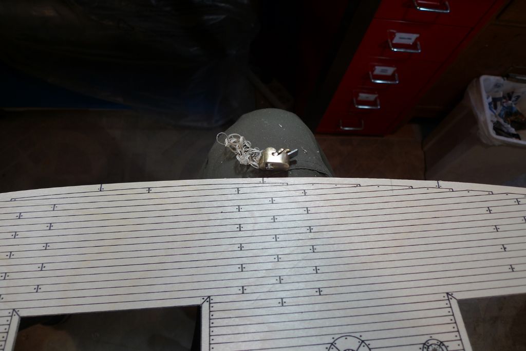
However, now that the problem has been solved, the deck as it is will fit well enough. It won't be a perfect fit, and on that account the kitmaker might perhaps have something to answer to, as the hull outer shape is of his making; however, as I am just going to use the plywood deck as a base on which to put down a second, planked pear wood deck, it does not really matter. I just want to be able to use the pre-printed planking pattern as a rough guide for placing the mast, the sheet through decks and various other bits and bobs, and this will now work just fine.
And of course, I will from now on measure not twice before cutting and glueing, but at least thrice …

Ian,
Thank you very much

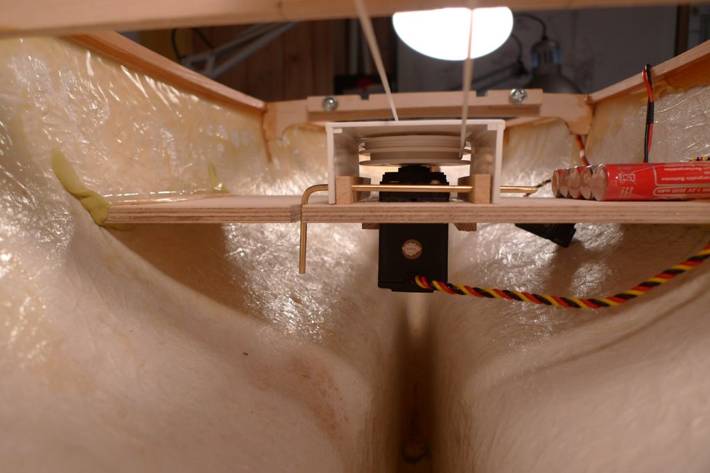
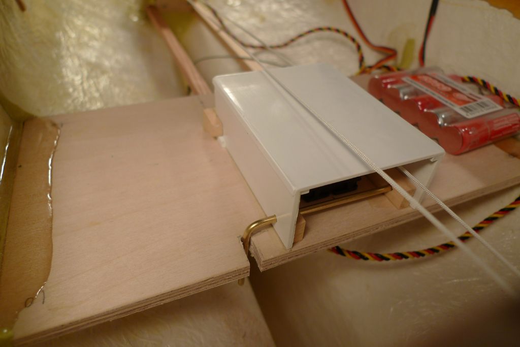
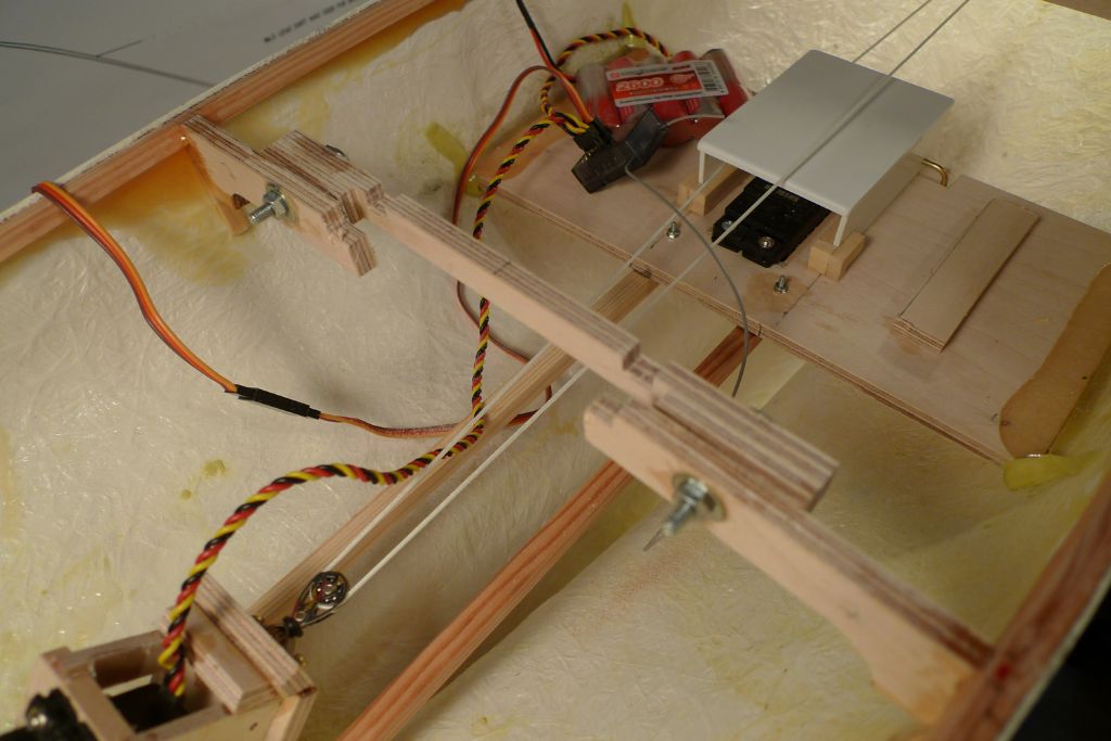
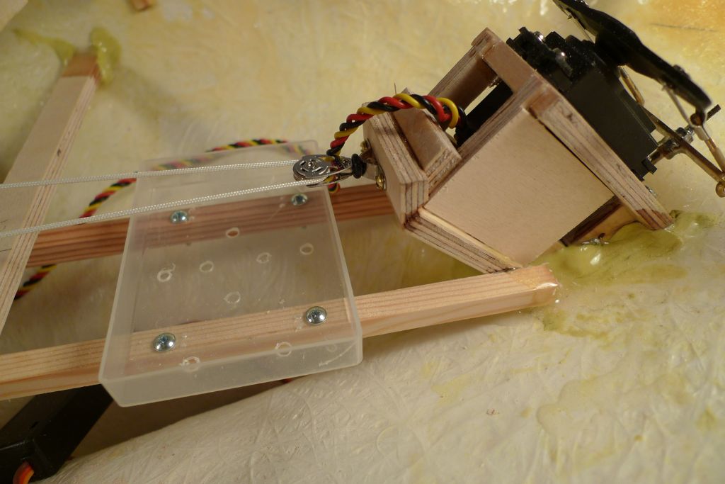
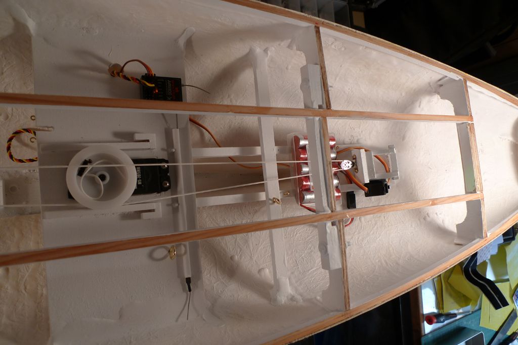
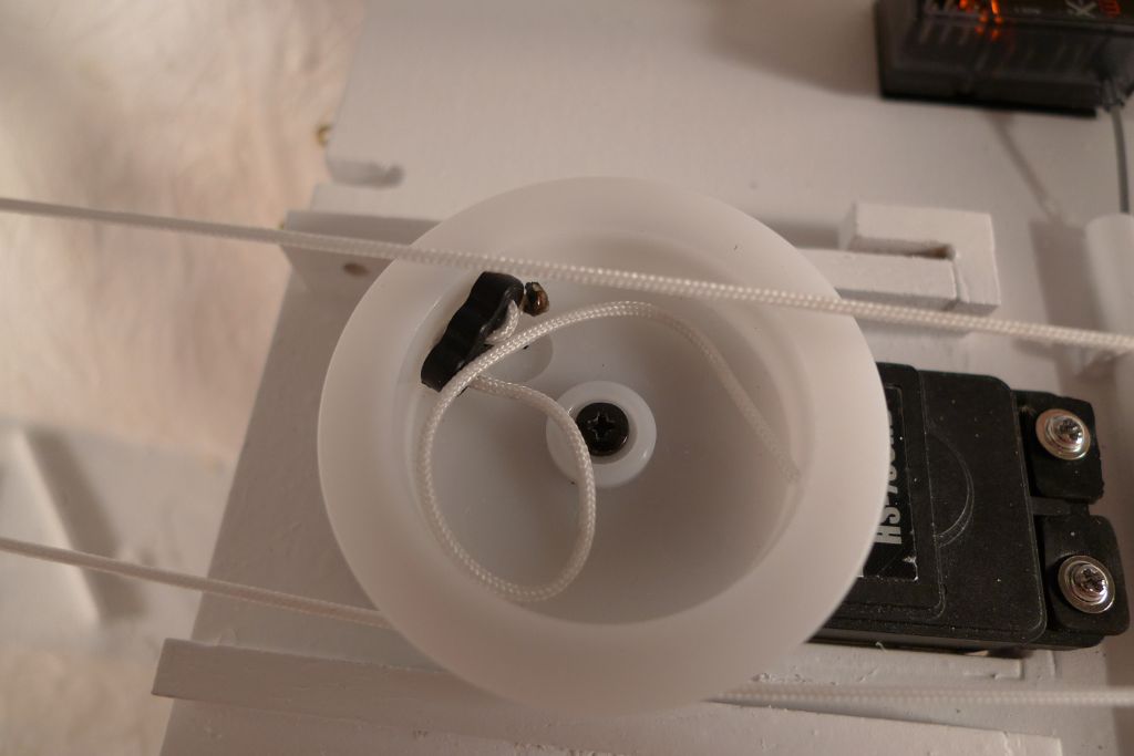
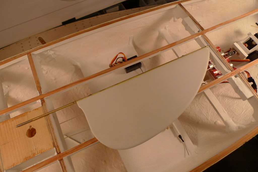
Any road, while all the epoxy was going off, yesterday, I also took in hand the job of making up a covering hood for the sail winch drum, to provide against slack sheets being accidentally pulled into it.
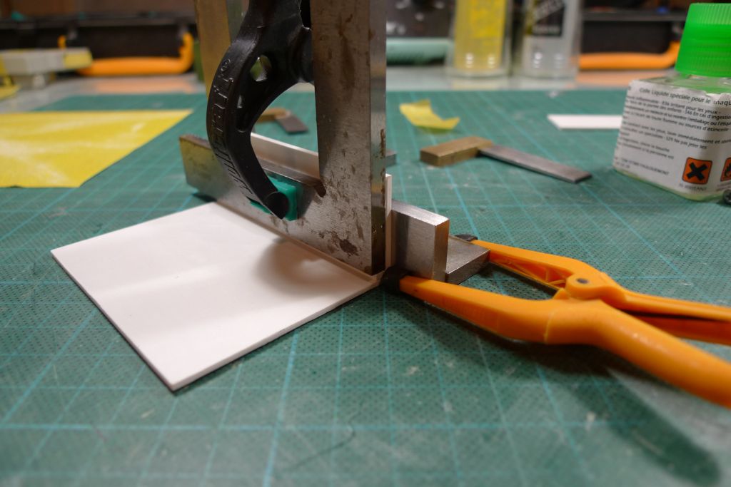
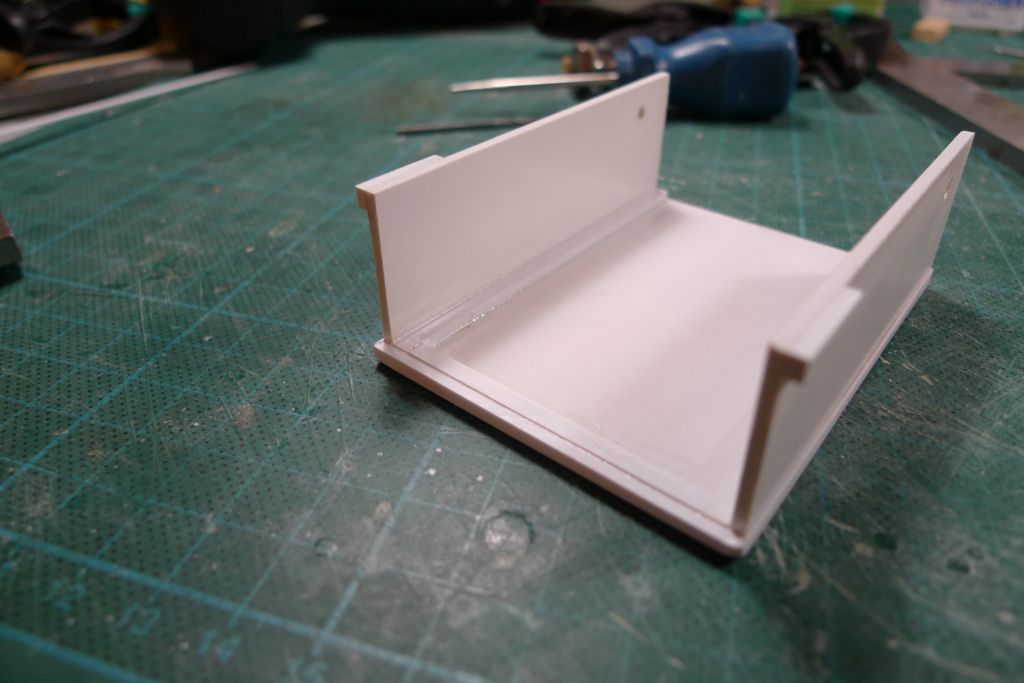
To this end, I cut out a couple of pieces of 1.5 mm (the top) and 2 mm (the sides) styrene sheet, and welded them together, wih corner reinforcements from 2.5 x 3.2 mm styrene strip.
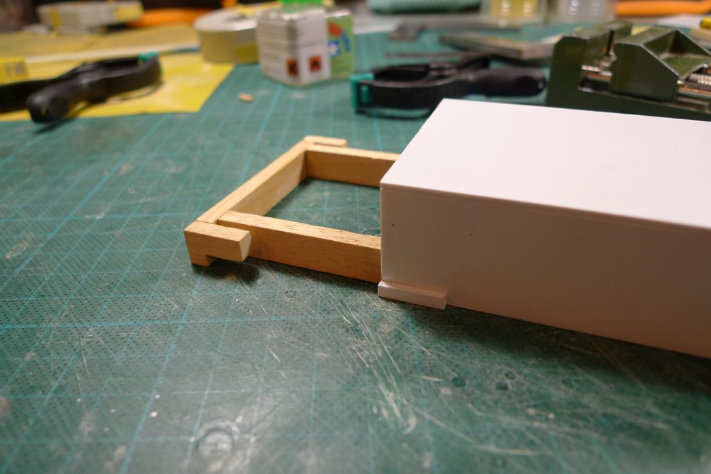
Two short lengths of the same styrene strip was then affixed to the outside, lower aft corners of the box, and a couple of wooden sliders with corresponding hooks made up from some scrap wood strip.
The box was then further reinforced, and the upper, outer edges rounded off; at the forrard lower ends of the two side pieces, 2.6 mm holes were also drilled.
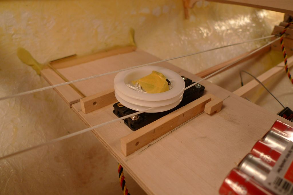
Matching holes were then drilled through the two wooden sliders as well, which were then glued down onto the winch holder on both sides of the winch.
The hood can now be slid under the after hooks, and a simple pin made from some 2.5 mm brass rod pushed through the holes at the forrard end, thus holding everything securely in place.
The brass rod pin is in its turn secured by its 90° bend being let into a slot, cut into the winch holder. In principle, I think gravity should be enough to keep it from unshipping; however, to be zartain shure, I will at a later tage add a small, elastic preventer across the slot opening.
I have also tested putting the hood into place and removing it again through what will be the avalable deck opening, and it works just fine. It is a little bit fiddly, but not too much so, and will, I think, be rather easier to manipulate if necessary than had it been bolted down, while at the same time being sufficiently well fixed in place not to come loose or move about to the detriment of proper winch, loop or sheet function.
To be continued …
/Mattias
Edited By Banjoman on 05/06/2016 12:03:43
Edited By Banjoman on 05/06/2016 12:04:34
Edited By Banjoman on 05/06/2016 12:05:03
Edited By Banjoman on 05/06/2016 12:06:14
Edited By Banjoman on 05/06/2016 12:07:03
5 June 2016 at 12:50 #65859Bob Abell 2
Participant@bobabell2Hello Banjo
Heavens above, Banjo………..I wouldn't criticise your workmanship, what so ever!
Bob
5 June 2016 at 18:53 #65865Banjoman
Participant@banjomanHello Bob,
Why not?! 'twas indeed I who mangled my measurements …

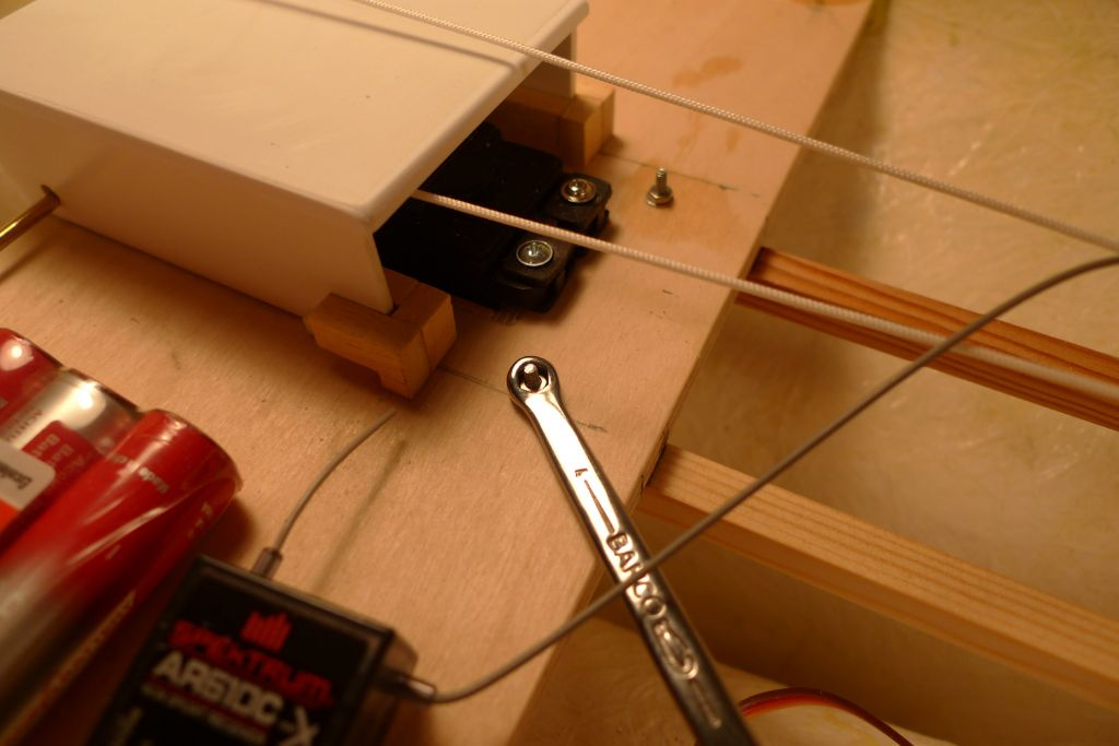
All that aside, I began today's bit of build with the rather small job of further securing the battery battens to the underside of the winch holder with a couple of M2 bolts. Not that I don't think the epoxy joint wouldn't be up to it, but still – when a glues joint is in a position were any accidental force would be applied pretty much dead on in the direction of the joint breaking, I do like to add brtaces to the belt in the form of a mechanical fixing, too …
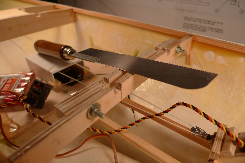
With that small job out of the way, it was time to get out a thin razor saw …
… and to carefully cut away the central part of the original deck beam …
… which was then glued back in its new place, up against the aft face of the bridging piece.
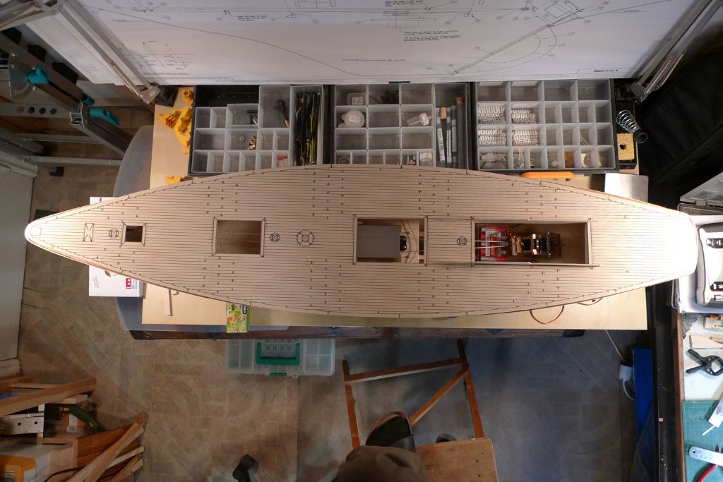
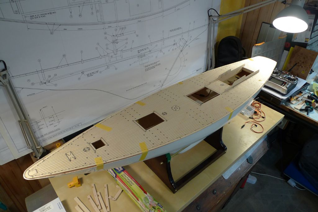
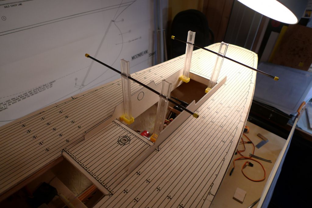
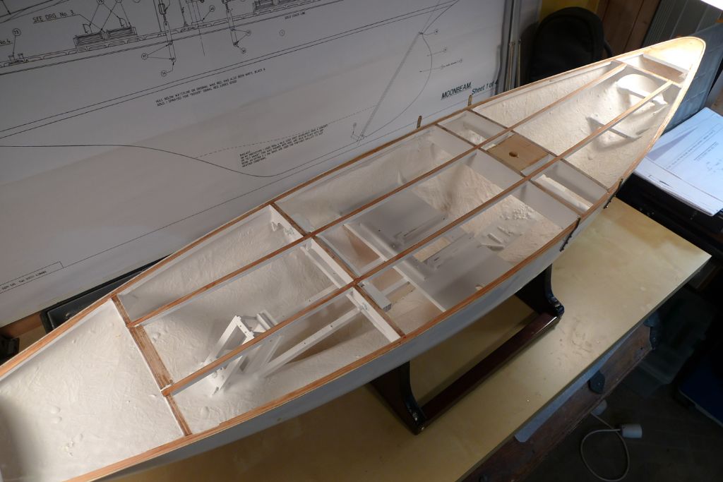
I then tried laying out the deck with the hull edges as a guide, and was very happy to note that the cockpit opening now corresponds perfectly with the two aftermost transversal deck beams!

The deck is perhaps not a perfect match to the hull …
… but had I intended to use only that, and not plank on top of it, I would have taken rather more care to check it for fit beforehand, and would have tried to do the necessary. As it is, it does not matter: where it is a tad over size, midships, I will shave off a few millimeters, and where it does not wuite reach the edge of the hull, I'll simply add some filler.
To be continued …
/Mattias
7 June 2016 at 12:26 #65907Banjoman
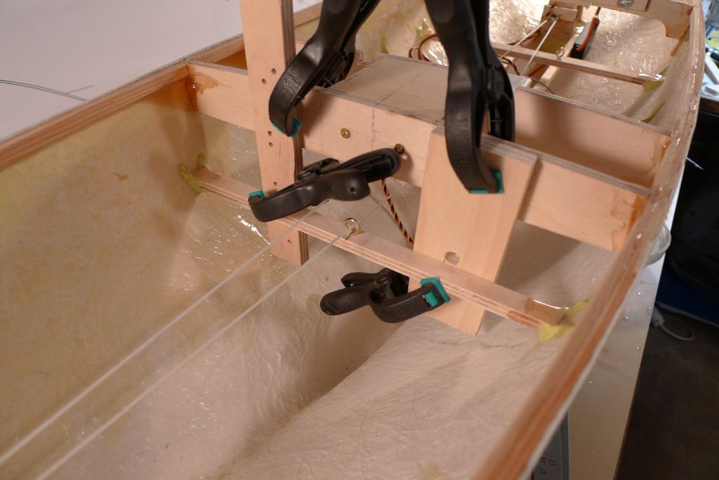
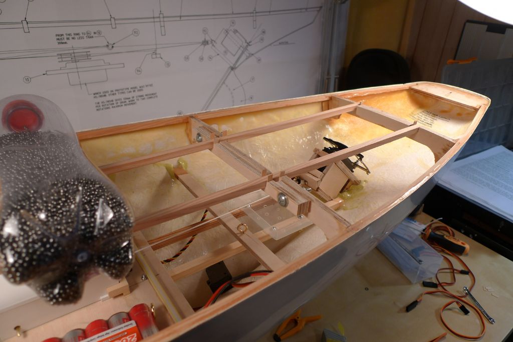
Participant@banjomanYesterday, I put in the lower beams that primarily serve to hold the eye-screws through which the sheets'll pass after coming down through the deck and before going on their respective points of attachment on the winch loop.
Before actually fixing anything in place, I took a length of (black) line and simulated the various sheet runs to verify that everything will work as it should …
… after which the beams could be glued in place, both the one for the foresail …
… and the one for the mainsail sheet. The jib sheet runs through an eye-screw on the short beam in the forepeak to which the forrard loop pulley is also attached, so there it was just a matter of adding the eye-screw to the beam already in place.
To be continued …
/Mattias
Edited By Banjoman on 07/06/2016 12:27:18
7 June 2016 at 15:12 #65913Gareth Jones
Participant@garethjones79649The cover over the sailwinch is well worth fitting. We discovered we had to add one to Elizabeth's Moonbeam after it had been completed and it was much more difficult to do a neat job when the deck was in place.
Gareth
7 June 2016 at 15:35 #65914Banjoman
Participant@banjomanyour Thank you, Gareth, for confirming my thinking — when I saw how close to the winch drum the sheets would have to pass, I did not feel comfortable about leaving it as suggested by the kit instructions. A bit of slack for whatever reason at the wrong moment, and a sheet would be very likely to be either pulled onto the drum or to get caught between drum and loop cord, with potentially less than agreeable results.
Oh, and there's another question I've been meaning to ask you, given Elizabeth's and your experience of the Moonbeam!
I've noticed that there are no real coamings around the deck openings. Have you had any problems when sailing Moonbeam with the deck becoming sufficiently awash for water to infiltrate via the joints between the deck and the superstructures?
/Mattias
Edited By Banjoman on 07/06/2016 15:36:46
Edited By Banjoman on 07/06/2016 15:36:58
9 June 2016 at 07:23 #65936Banjoman
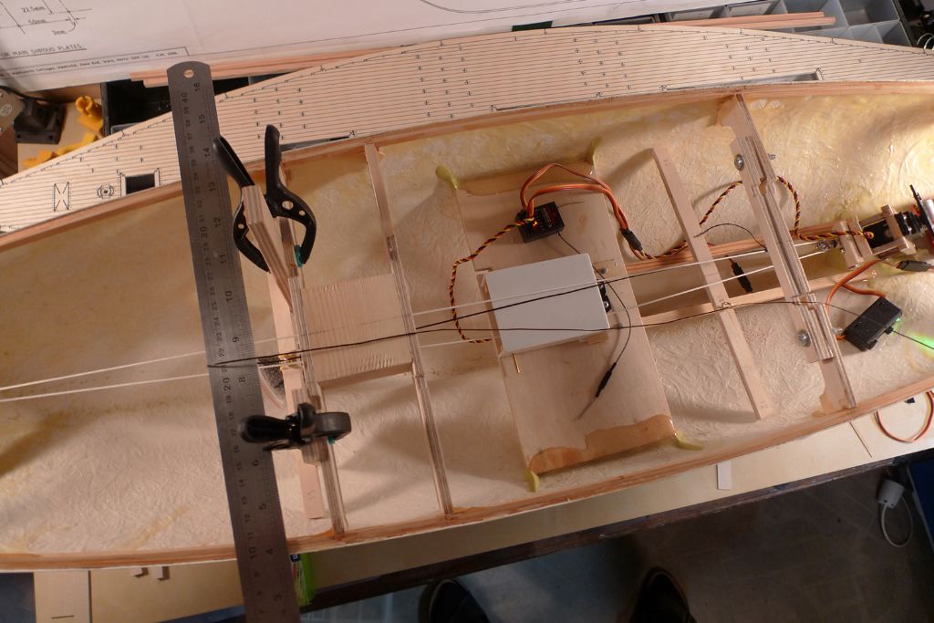
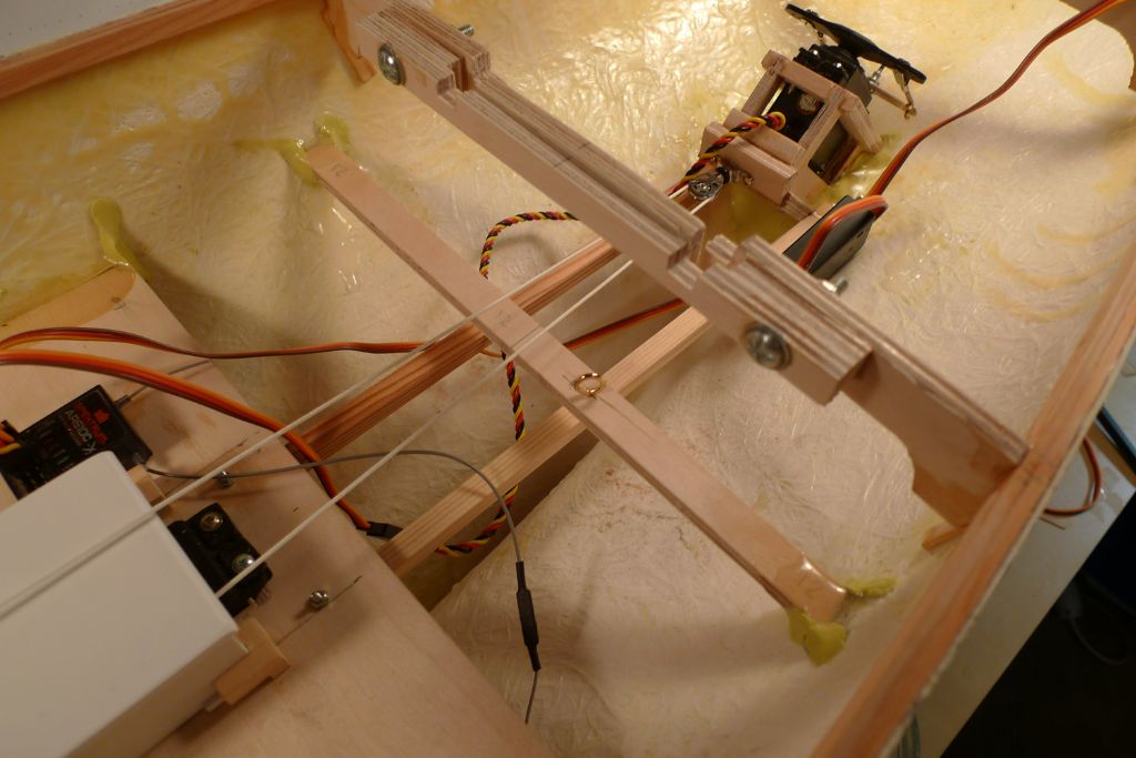
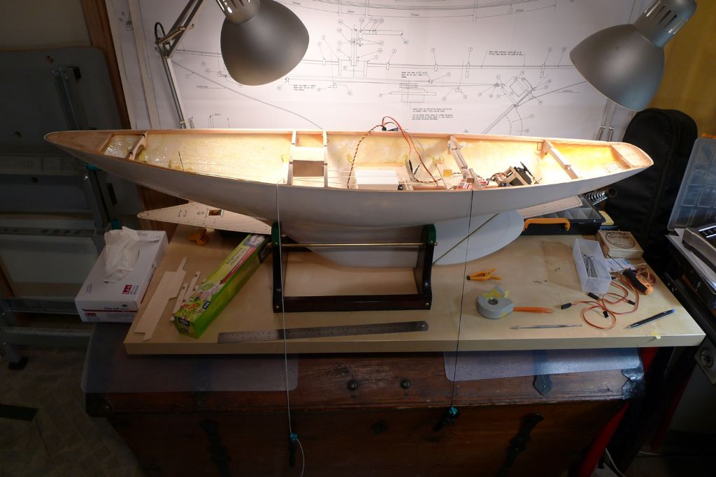
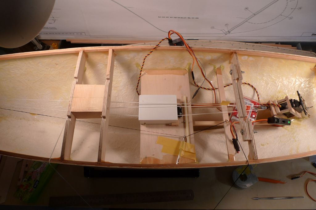
Participant@banjomanWith the lower beams in place, I carried out a few more test sheet runs, with a couple of lines weighted down outside the hull to simulate the fore and main sheets …
…. specifically in order to test the idea of adding a second eyescrew to port of the sail winch to give the main sheet a completely free run, well clear of the winch hood.
For test purposes, I taped down a small ring key in the position required, and found that this set-up did indeed seem to work quite well.
Given that this sets the main sheet at an angle to the winch loop, rather than parallell with it, while the foresail sheets will be just that — parallell — there will be a slight difference in the total run length of these two groups of sheet. From my roughish measurements in situ, at 65% winch rotation (which is more or less what I plan to use) the main sheet run will be some 3 mm or so shorter — 275 as opposed to 278 mm, or in other words a difference of just over 1%. I am sufficiently convinced that this difference will be negligable, and thus feel justified in going for a set-up that should give the main sheet a much smoother run.
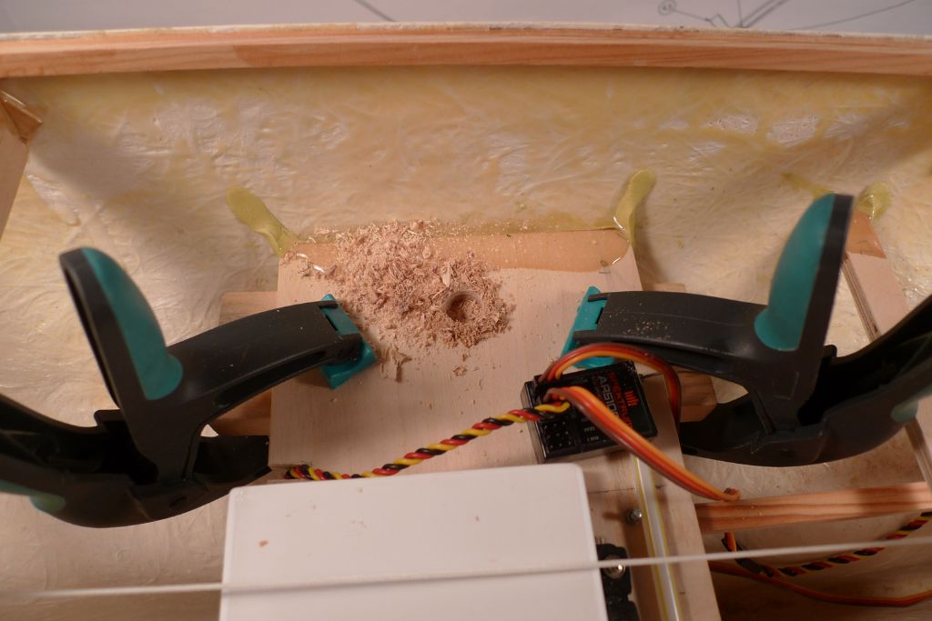
I also drilled a 12 mm hole through the winch holder on the starboard side …
… for the wires connecting to the receiver to come up through, so that they can be given a run in the lower parts of the hull, well out of the way of the sheeting arrangement.
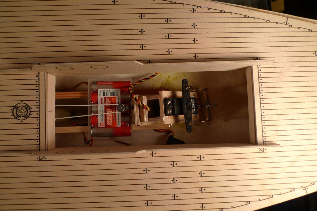
I also glued a length of drinking straw parallellel with the after edge of the winch holder. By pushing the receiver antenna into this, it can be kept nice and straight and, at the same time, well protected from the sheet and loop runs. If one looks carefully, one can also see that the second eyescrew for the main sheet has been added.
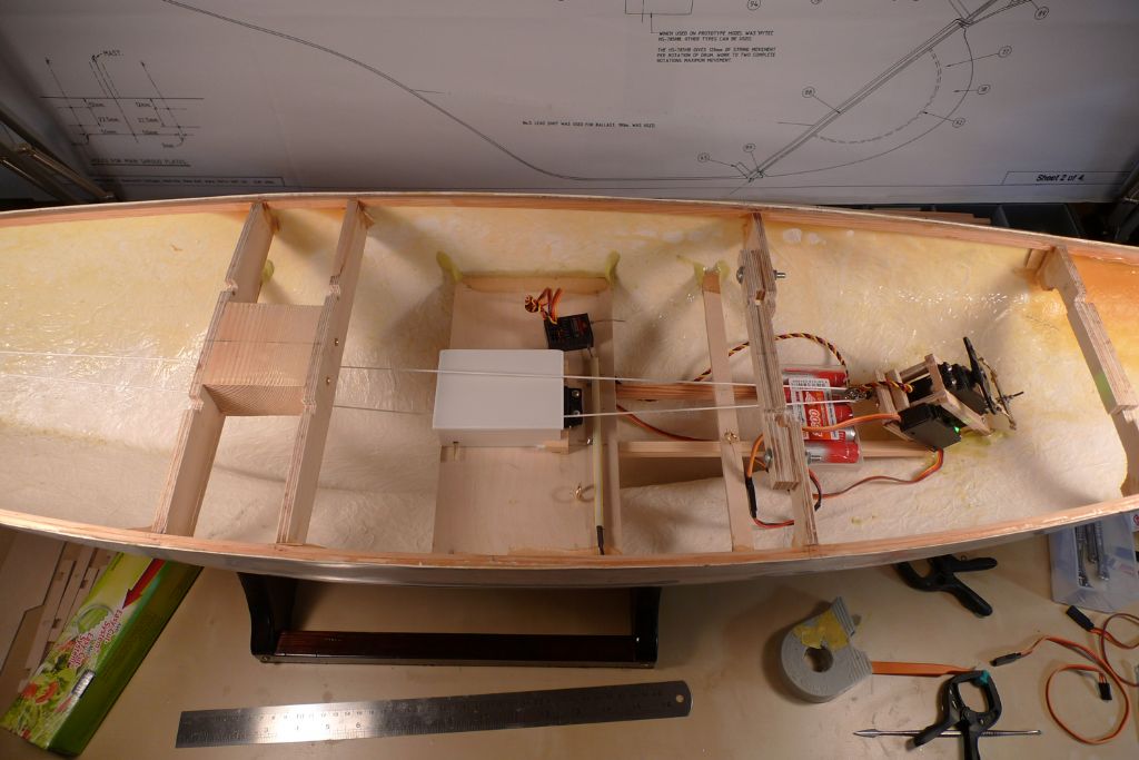
I have also screwed down a small plastic tray that I found in my box of bits and bobs, which happens to fit the battery pack quite nicely, and have also glued a piece of 1.5 mm plywood to the side of the rudder servo box to serve as a base against which to attach the on/off switch.
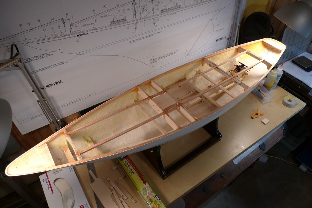
With the above jobs sorted, the technical installation is as good as done, and it was thus time to put in the fore-and-aft deck beams.
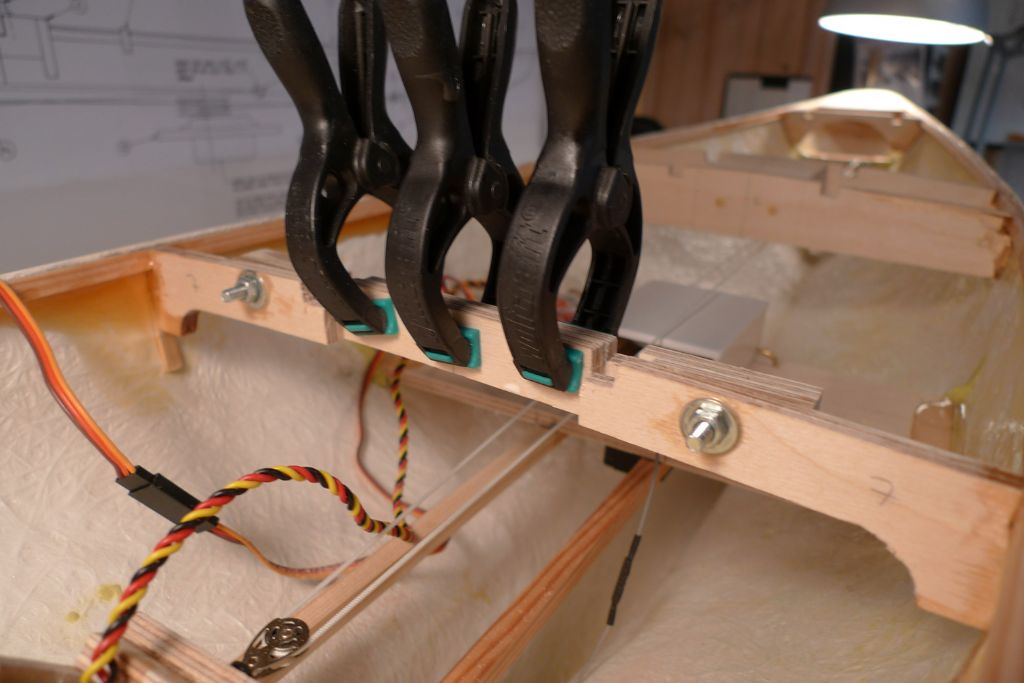
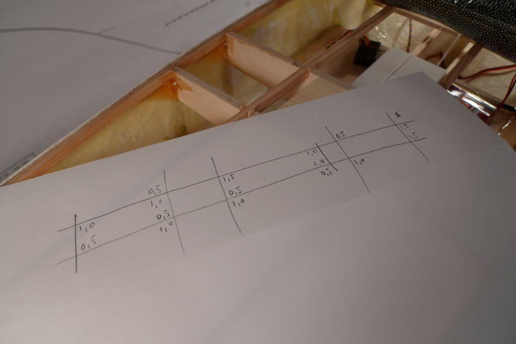
These sit in slots in the athwartship beams, and as these slots had been CNC routed a tad too large, I decided to add shims, partly for the purpose of filled-up, more solid joints, but primarily to make sure that the fore-and-aft beams would (a) be perfectly parallell at 80 mm apart, at least from the stern up until the mast, and (b) would be exactly the same distance in from the port and starboard sides respectively.
This is very important, as these beams will form the fore-and-aft coamings for the cockpit and large skylight assemblies, and thus must provide an opening of just the right size which is perfectly centred along the fore-and-aft axis of the hull.
To this end, I cut off some short pieces of 0.5 and 1.0 mm maple strip and proceeded to dryfit these in all the beam crossjoints until I was happy with the result.
I then made a careful note of the combination of shims ..
… took out the dryfitted shims again, made up a batch of 24 hour epoxy, and glued everything in place.
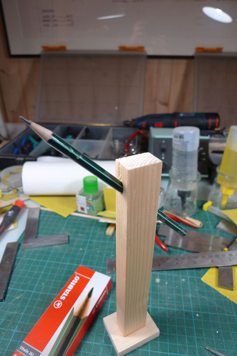
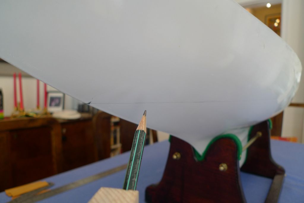
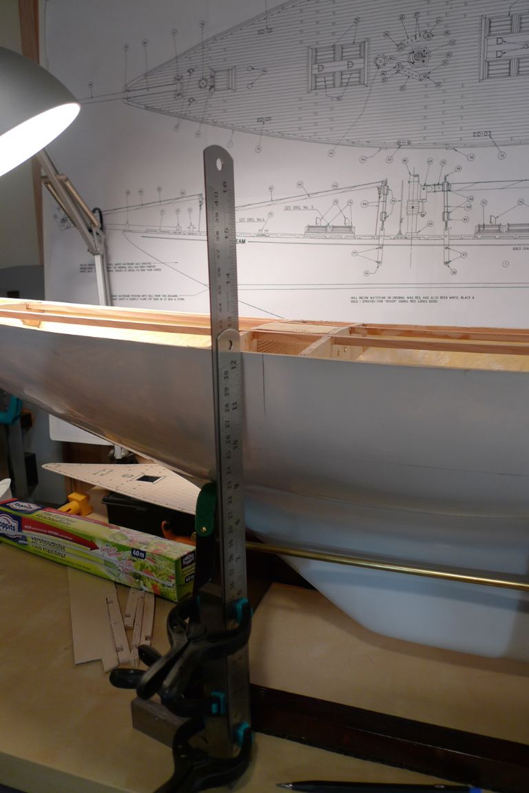
The final job last night was to make up the suggested form of waterline marker, in the form of a pencil passed through a 45° hole in a length of wood with added foot.
To be continued …
/Mattias
Edited By Banjoman on 09/06/2016 07:24:14
Edited By Banjoman on 09/06/2016 07:26:06
Edited By Banjoman on 09/06/2016 07:28:22
13 June 2016 at 11:50 #65998Banjoman
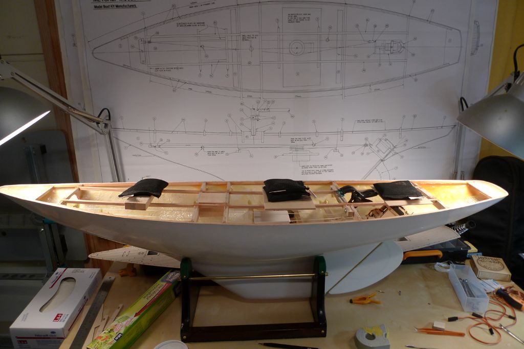
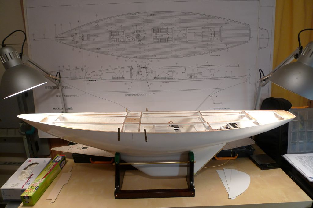
Participant@banjomanWith the fore-and-aft beams duly and permanently in place, it was time to turn the attention to getting the boat ballasted. According to the instructions, this should actually have been done before putting in most of the internal structures, when access to the depths of the keel would have been more free, but for various reasons I decided instead to wait until the current stage of the build.
Anyway, I cleared the interior of the entire technical installation (except the rudder servo, to keep the rudder from swinging about) …
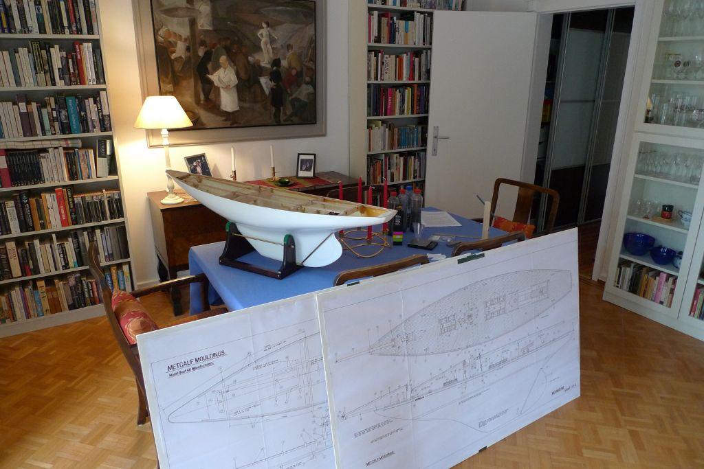
… and then brought the hull up from the workshop into our dining room, where the dining table provides a sufficiently large and flat surface accessible from all sides (and where the bathtub test tank is closer to hand).
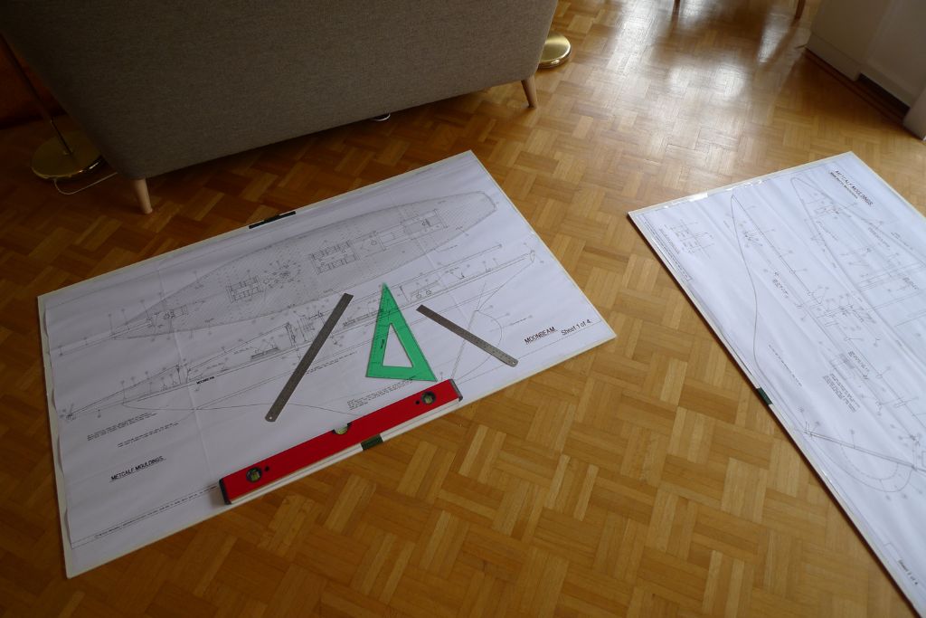
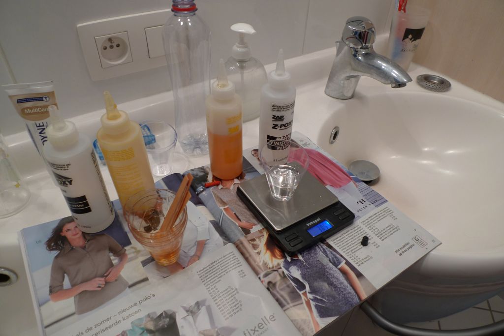
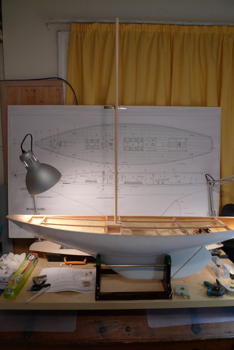
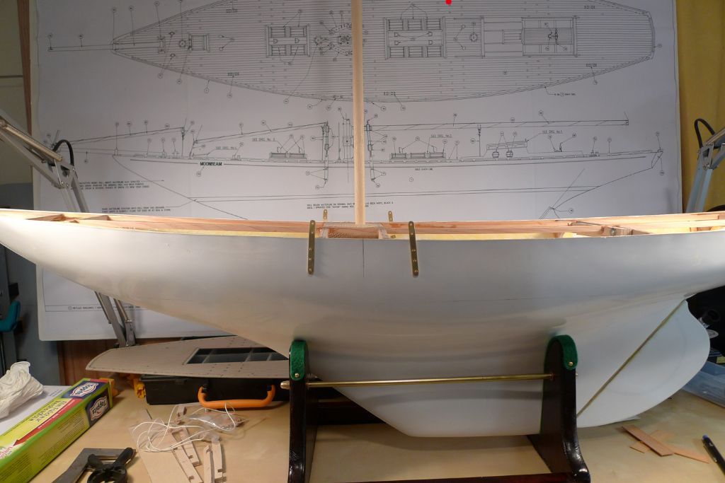
Along with the hull also came the plans, 7.5 kg of lead shot, plenty of Z-Poxy Finishing Resin, a set of scales, the waterline tool and various other bits and bobs.
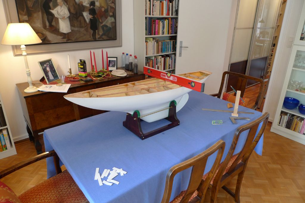
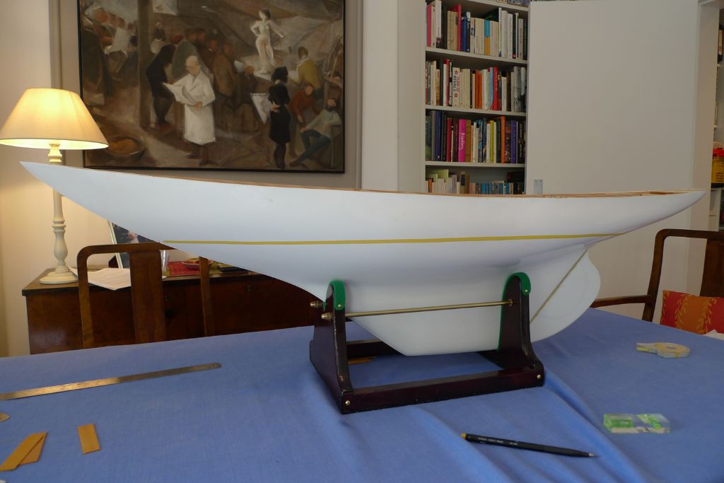
I began marking out the waterline by checking that the hull sat level on the table, adding shims under the stand as needed …
… carefully measured the waterline positions at the bow and the stern on the plans, marked these positions onto the hull …
… and connected them together by running the waterline tool along both sides of the hull.
I know from experience that in a bathtub situation, where the water is very clear, it can be a tad tricky to ascertain whether a thin pencil line sits just above, at or just below the surface of the water, so I reinforced the waterline visibility with two lengths of 6 mm masking tape just above the pencil line (which represents what will be the lower edge of the painted waterline).
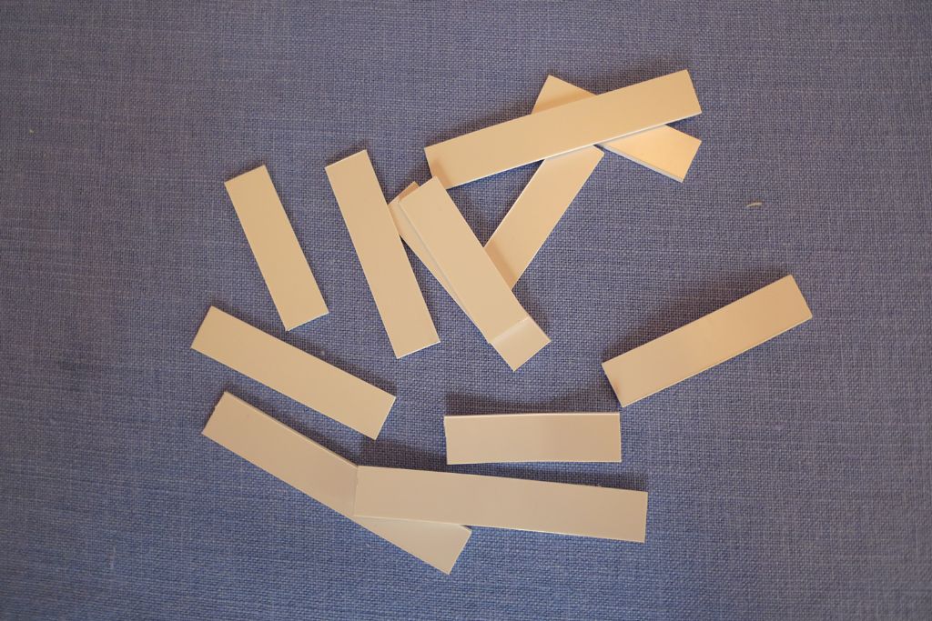
Among the bits and bobs that I'd prepared were also a set of 1.5 mm styrene strips, 14 mm wide and either 50, 60 or 80 mm long.
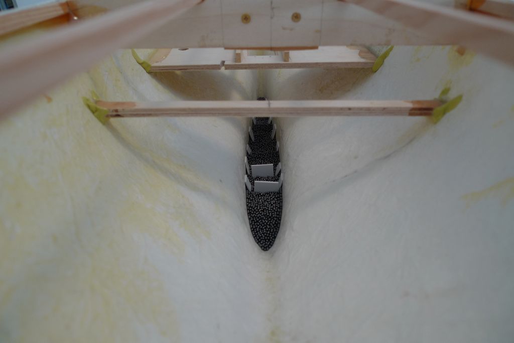
These strips were folded in the middle, and set down into each layer of lead shot added, so that the ends would spring outwards from the middle, and sit against the keel walls.
The idea here is to further ensure that the lump ballast won't fall out under its own weight when the hull is turned upside down (for example when it is painted) by adding some mechanical resistance to the otherwise resin-based securing of the lead. I don't know whether it would really be necessary, nor how much of a difference it'll make, but as it was very easy to do, and wouldn't in any case hurt, I figured it was worth the (rather minor) additional effort.
The pieces of styrene sticking up in the middle of the lead are in their turn there to help keep the higher levels of lead shot needed towards the bows from slipping down back into the centre of the keel.
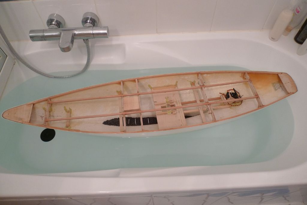
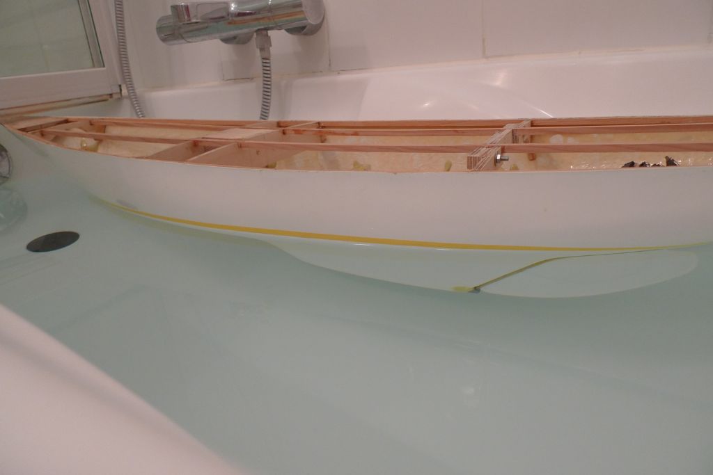
At the table, I put in the first nine pounds of lead shot, after which the hull was brought across to the bathroom, and set down into the waterfilled bathtub.
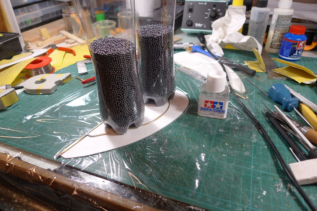
Here, another four pounds of lead shot was added, one pound at a time, and pushed towards the bows as necessary, until I was happy with how she sat in the water.
It was then time to make up the necessary amount of finishing resin, one 60 gram batch at time …
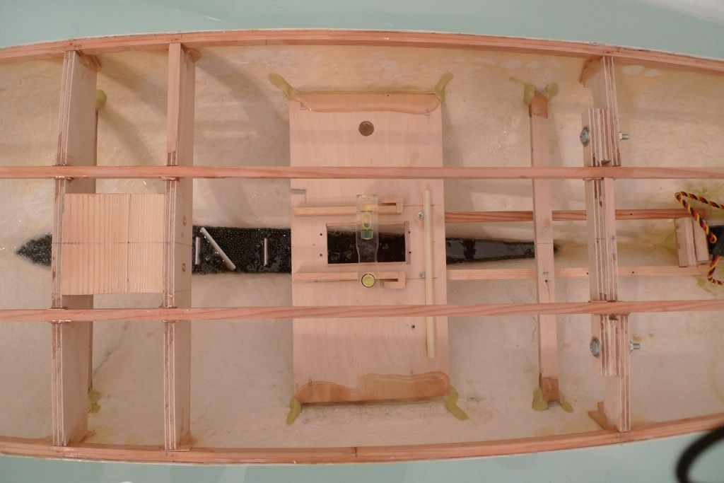
… until a total of one pound of resin had been poured over all parts of the lead shot, while a small spirit level helped to make sure that the ballasting was done on an even keel.
With the abovementioned weight added, the masking tape representing what will be the painted waterline sat just above the water in a nice and even fashion, all around the hull, which should give me enough of a margin for the weight of the additional construction to come.
To be continued …
/Mattias
Edited By Banjoman on 13/06/2016 11:51:23
Edited By Banjoman on 13/06/2016 11:51:52
Edited By Banjoman
13 June 2016 at 13:43 #66002Gareth Jones
Participant@garethjones79649Hi Mattias,
We have not really had any problems with water ingress into Elizabeth's Moonbeam, although it is usually sailed as a fair weather boat so it is not often exposed to high winds or well heeled over. The hatches fit quite snugly and the hull is reasonably large so it is not affected by general splashing and small waves as a smaller yacht would be.
If you wait till you have sailed it a few times and are satisfied everything has settled down, you could seal the hatches that you dont need to remove for battery access with a bit of silicone sealant. They could still be prised off later if need be.
Gareth
13 June 2016 at 13:50 #66003Banjoman
Participant@banjomanHi Gareth,
Many thanks for your helpful (and reassuring!) reply! As I am certainly planning for my Moonbeam to be a fair weather boat, and don't intend to do any racing or other more strenous sailing, I shall build the superstructures as instructed, see where that gets me on the pond and then take measures, if any are needed.
/Mattias
14 June 2016 at 10:01 #66032Banjoman
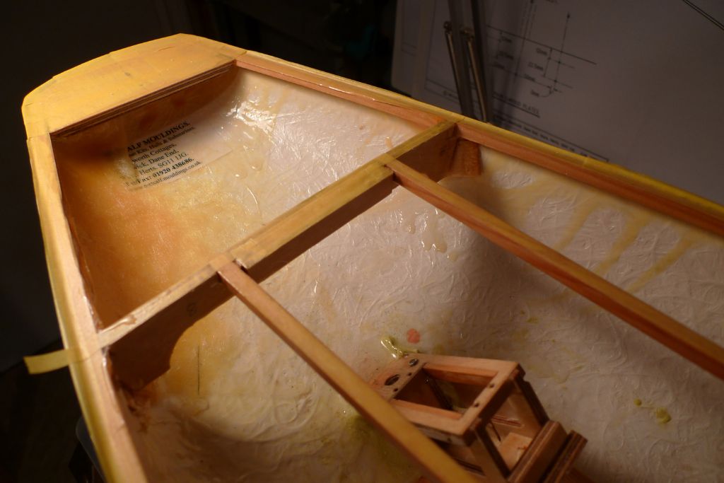
Participant@banjomanWith the fore-and-aft beams in place, it was now not only possible but also very easy to determine exactly how the deck should sit, by simply pressing the cockpit side pieces against the beams. As this is all a nice, tight fit, there is only one way that the cockpit hatch can sit against the four surrounding beams with the sides in place, and everything else just follows from there.
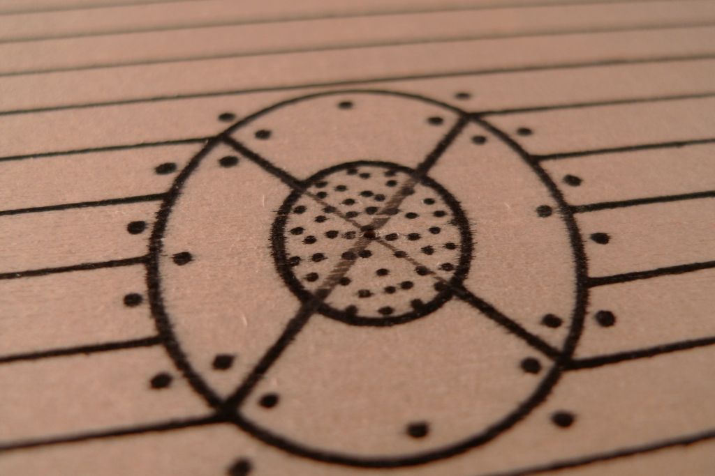
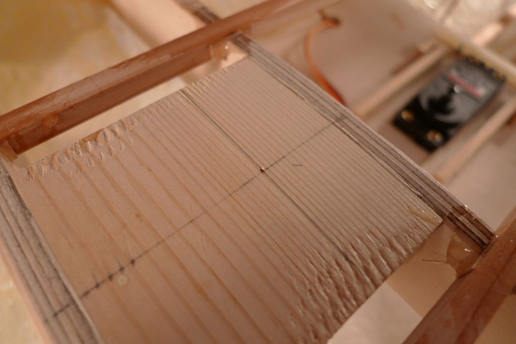
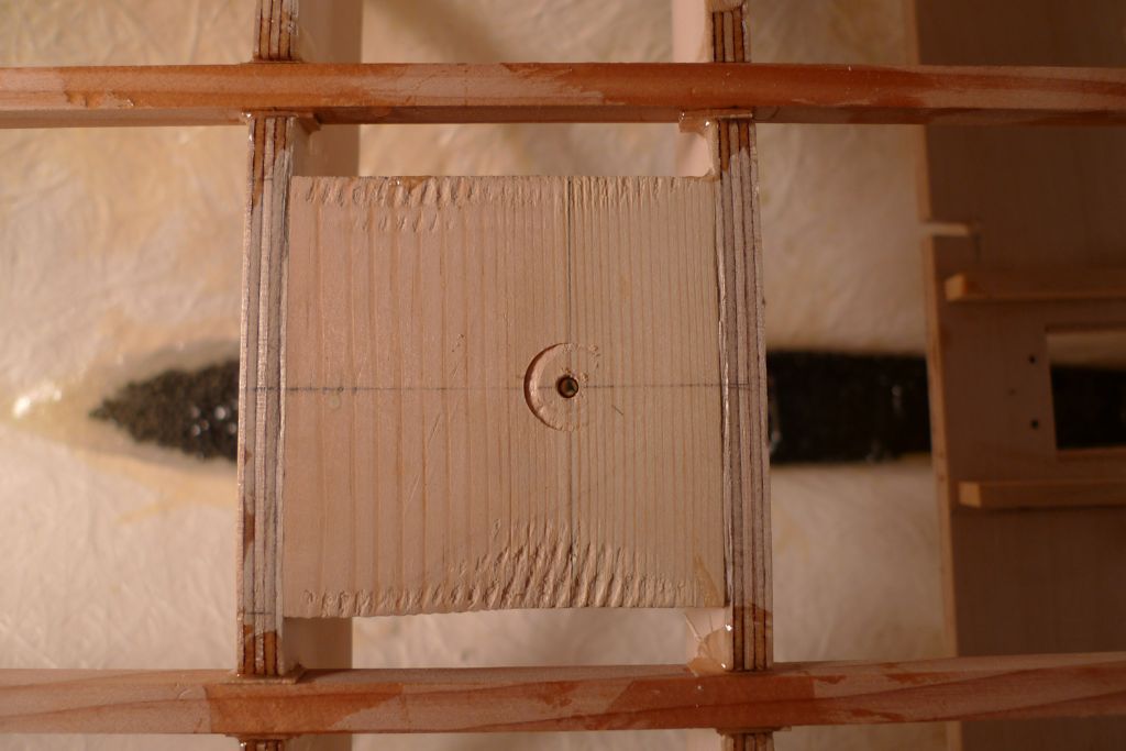
This also meant that the exact location of the mast could now be found, so I marked out the centre point of the preprinted marking for the mast on the deck, and pushed a sharp, thin awl through the plywood …
… to mark the corresponding point on the underlying mast support block.
I was most pleased to note that the hole came to sit within about 0.25 mm of the previously established centre line, something that rather vindicated the care taken to get the longitudinal beams just so.
I then set the hull up in such a way that the waterline was level with the work top, and proceeded to transfer and mark out the central mast plumb line on both sides of the hull to serve as reference for the main shroud plates.
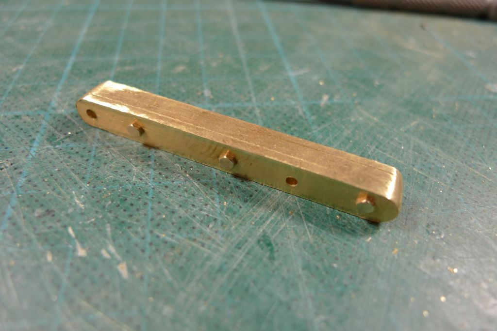
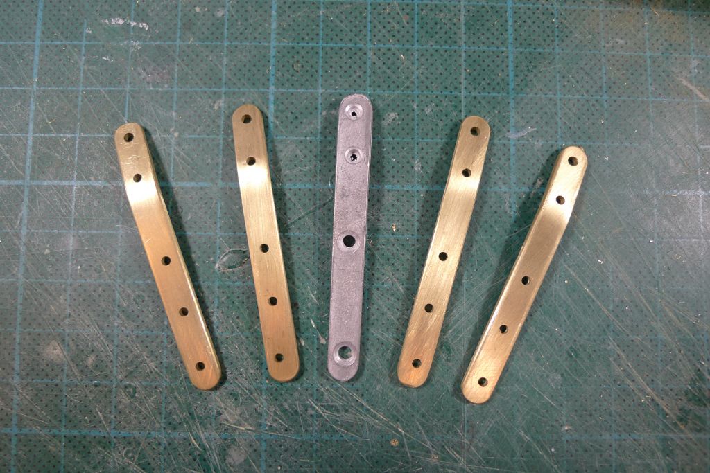
These shroud plates as furnished with the kit are made from white metal, a material that I don't really trust for any load bearing parts or parts under strain, unless they are sufficiently solid and/or massive.
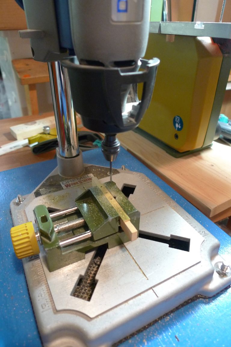
This, in my view, was certainly not the case here, so I had early on decided to make up a new set of shroud plates from brass strip. My first attempt failed, though, as my Dremel drill press was not steady enough to stop the drill bit point from dancing all over the surface of the brass strip before consenting to drill a hole that then was more likely to be off centre than on.
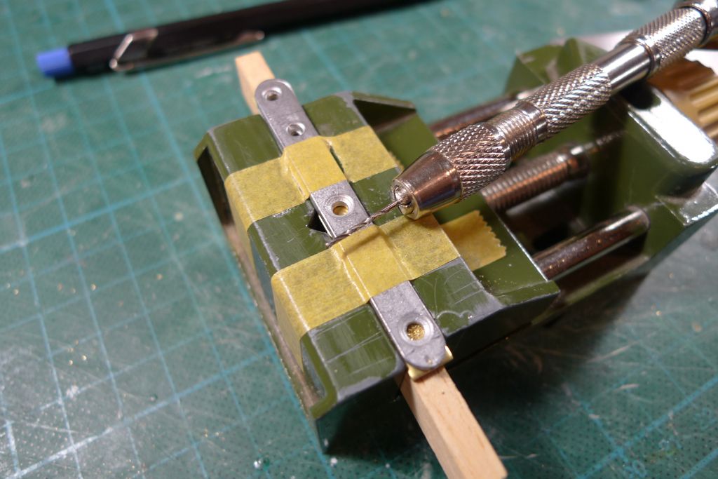
For my second attempt, I therefore made up a drill jig from a spare piece of strip, which I initially pre-drilled with a hand held 0.9 mm drill bit, using the original shroud plate as a guide.
This pre-drilling permitted a safe enlargement of the holes under the Dremel …
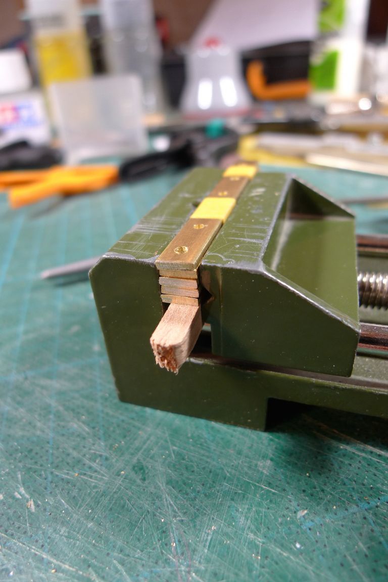
… after which the drill jig was set up inthe small machine vice together with the four shroud plate blanks, and the latter drilled through together.
The drilled-out blanks were then bolted together with M1.6 nuts-and-bolts, and the edges and ends rounded off against a sanding drum in the Dremel …
… and finally polished and bent to the same angle as the original plates, after which I had four identical brass shroud plates to replace the white metal ones.
Instead of using countersunk bolts to secure the shroud plates to the hull, I shall use hex bolts, so there'll be no need to countersink the holes; however, as the hex bolts are M1.6 rather than M2, I shall use three per plate instead of the two foreseen for the originals.
To be continued …
/Mattias
Edited By Banjoman on 14/06/2016 10:03:37
27 June 2016 at 09:13 #66216Banjoman
Participant@banjomanAfter a week away from the build for a family visit, I was back in my workshop last Friday, and began by drilling a 3 mm pilot hole through the mast support block at right angles to the waterline.
With this pilot hole as a guide, a 12 mm diameter hole was drilled +/- 15 mm down into the block at the same right angle to the waterline. The lower mast blank is 12.5 mm, and so for the moment still a slightly too tight push fit; however, I shall wait with getting the final fit sorted until after the deck is in place and the mast has been worked to final shape. What I wanted to achieve here was to get the basic hole done at the correct angle.
With that out of the way, it was time to get the shroud plates fixed in place.
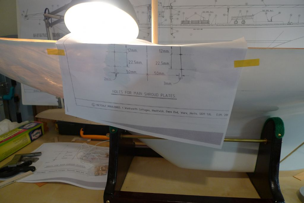
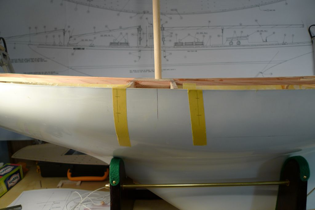
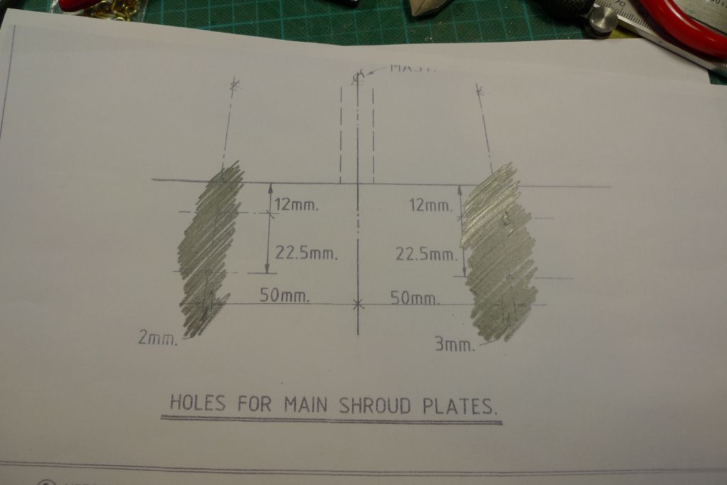
To this end I made a couple of photo copies of the corner of the plans were the location of those plates is given in relation to the mast centre line that I had already marked out on both sides of the hull.
Some masking tape was applied to the hull, and the back side of the first plan copy given a pencil shading; the paper was then positioned up against the hull, and the shroud plate lines traced with a pencil from the front …
… to get a pencil tracing on the pieces of masking tape.
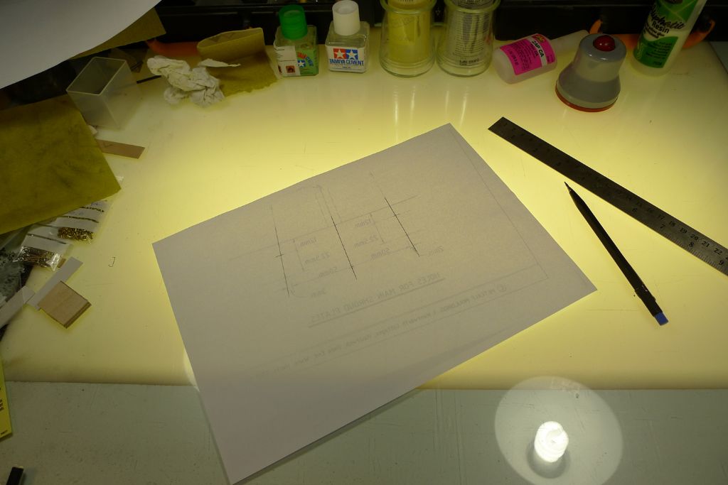
For the starboard side, the drawing had to be reversed, and although I could of course have achieved this by scanning the drawing and flipping it over in the computer, I decided instead to take advantage of the fact that my main work top is an old drawing table complete with a still working light box. The lines were thus transferred to the reverse of the paper …
… and the soft pencil shading added to the actual drawing and subsequently traced onto the hull.
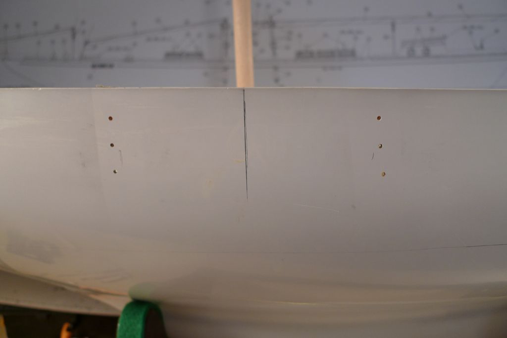
Next, the uppermost holes for the securing bolts were drilled, undersize by about 0.1 of a mm so that the threads of the M1.6 bolts would actually get a slight grip on hole, and the plates attached to pivot around this single point only.
The remaining two fastening holes in each plate could then be used to guide the drill …
… and thus get all holes through the hull sides perfectly spaced and correctly lined up against the fastening holes in the plates.
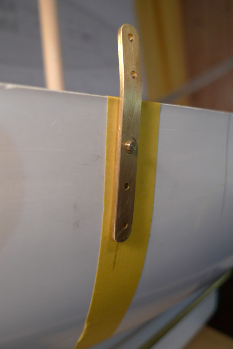
Next, the GRP was slightly roughed up with some coarse sand paper for a better key, and the shroud plates attached with 24-hour epoxy …
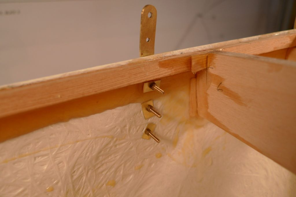
… and at the same time bolted in place with M1.6 nuts-and-bolts. I also made up some very simple washers from 0.10 inch brass plate, drilled through and cut into small pieces, to go under the nuts.
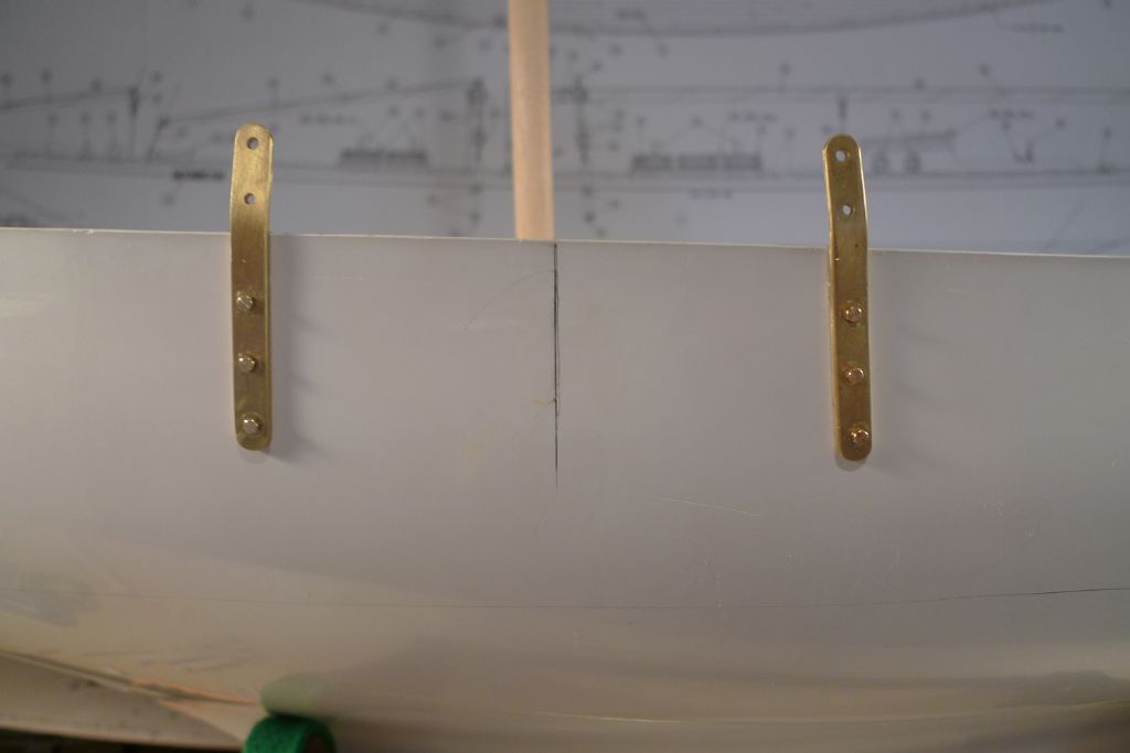
With all four shroud plates in place …
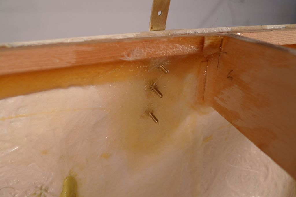
… the job was finished off with the addition on the inside of the hull of some glass-fibre-and-finishing-resin reinforcements around the extruding bolts.
To be continued …
/Mattias
Edited By Banjoman on 27/06/2016 09:14:56
Edited By Banjoman on 27/06/2016 09:17:49
27 June 2016 at 12:05 #66222Banjoman
Participant@banjomanAnd then, on Saturday, I had a rather nasty surprise when I discovered that, for a reason unknown to me, the rudder had completely seized up and would not move at all!!!
I found this out when I removed the steering servo in order to waterproof its holder. When I last tried the rudder, just before installing the ballast a couple of weeks ago, everythng was fine; now, it would not budge at all.
The only explanation I can think of is that, when securing the ballast, I must inadvertently and without noticing have let fall a droplet of finishing resin smack dab onto the top of the rudder tube, and that this subsequently slid down into the tube and locked the rudder post fast.
In any case, after more than an hour of attempting to wiggle things loose again, with no success whatsoever, I came to the inevitable conclusion that I would have to remove both rudder and tube, and start this bit of the build over from scratch.
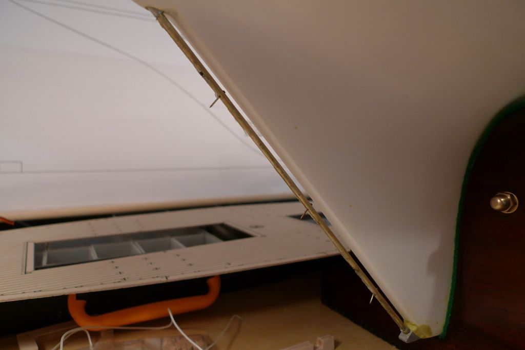
I therefore carefully broke off the rudder blade from the post …
…cut off most of the lower part of the post …
… and then very, very carefully indeed knocked the offending article, together with the remainder of the post still locked inside it, out of the hull.
Even with the tube and post out of the hull and set up in a vice, it remained completely impossible to break the lock, so whatever caused it, it caused it good and proper!
Although this is of course a bit of a set-back, it could also have been much worse: had I not found this out before glueing the deck in place, it would have become even trickier to sort out the problem. As it is, I do at least have decent access to both ends of where a new rudder tube shall have to go.
Furthermore, as I had completely filled the space through which the tube passes, between the servo box and the hull, with epoxy glue, and the old tube came out without undue duress or excessive use of force, I still have an intact tunnel at the exact angle required through which to fit a replacement rudder tube.
The only slightly tricky bit will involve the fact that the skeg is no longer loose, and that I must therefore take care to preserve a sufficient margin of vertical manouvre, so that the rudder can be lifted high enough for the lower post end to be let down into into the skeg bearing.
On the other hand, this gives me the opportunity to do better, and improve what I think might have become weak points in the construction of the rudder assembly, particularly as regards the fastening of the blade and of the tiller arm to the post. In other words, an opportunity to do a better job of work …

To be continued …
/Mattias
Edited By Banjoman on 27/06/2016 12:06:52
Edited By Banjoman on 27/06/2016 12:07:30
27 June 2016 at 17:21 #66225Ian Gardner
Participant@iangardner62867Mattias,
Always interesting to see how you tackle things, lovely job on those chainplates- and what bad luck about the rudder. You seem a very measured man but even so- I wonder if the air was bit blue in the workshop that day! It would have been in mine- often is!
Ian
27 June 2016 at 21:16 #66233Banjoman
Participant@banjomanIan,
Many thanks for your kind words! I will admit to having been less than delighted in a tent, and a certain discoloration of the surrounding airspace did indeed make its presence known.
Still, as I said, it does mean I will hopefully be able to do a better job of it, so on reflection there is at least a narrow silver lining to be spied amongst the cumulonimbae …
/Mattias
1 July 2016 at 10:02 #66294Banjoman
Participant@banjomanMaking up and installing the new rudder shall have to wait until after our summer holiday travels, so for the time beaing I have rather pushed on with getting the hull internal structures finalised.
To this end, the upper wood surfaces, against which the plywood deck will be glued on, were masked off, and all other wooden surfaces given a couple of coats of finishing resin.
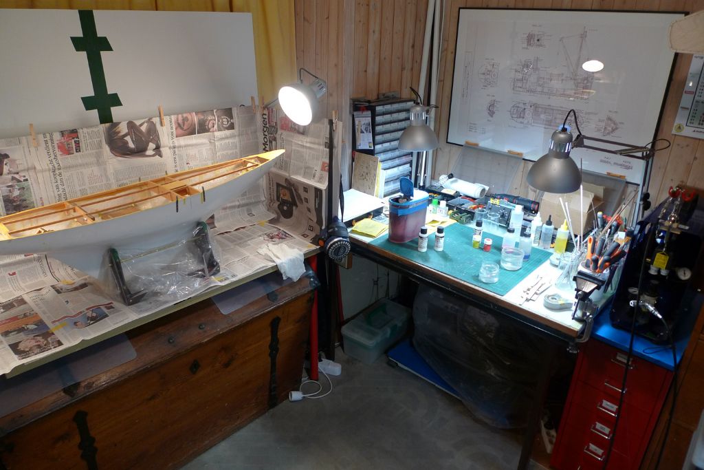
The workshop was then re-rigged for airbrush painting …
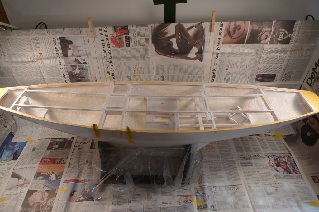
…and the hull interior given one coat of white primer …
… plus a couple of coats of white paint, after which the masking tape was removed.
As paint jobs go, this one was fairly slapdash, as its main purpose is as an addition to the water-proofing treatment; however, to the limited extent that things will be visible through the hatches, I also think it looks nicer to have the visible bits of the various materials, glues etc. within the hull interior all painted the same colour, and at the same tide hide to some extent the various marks, blobs and discolourations that have come about in the build process.
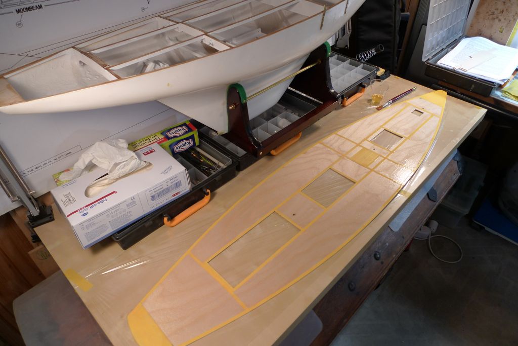
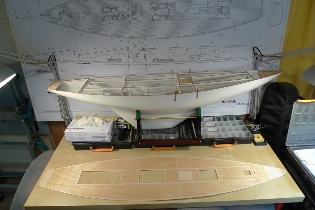
Next, the plywood deck was planed down along the outer edges to a final fit …
… the bits corresponding to the beams etc. masked off, and the deck underside given a couple of thin coats of Z-Poxy finishing resin to water-proof it.
To be continued …
/Mattias
Edited By Banjoman on 01/07/2016 10:04:19
2 July 2016 at 15:39 #66326Banjoman
Participant@banjomanWith the resin dry and the masking tape peeled away, the underside of the deck has got a nice sort of bikini tan …

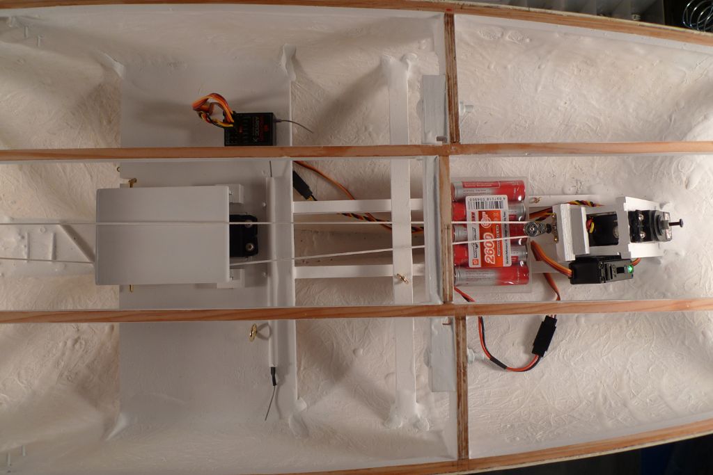
With all the sticky work inside the hull sorted, the r/c installation could start to go back in, so the receiver and on/off switch were secured in place with some self-adhesive velcro …
… and the sail winch continous loop made fast with a knot at one end and a bowsie at the other.
The rudder servo went in as well, as did the sail winch hood.
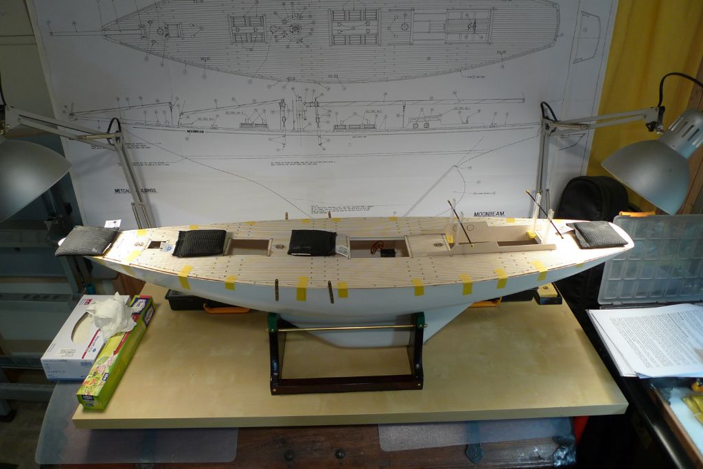
The build is going to go on hold now for a while, so as it is just sitting there, I decided I might as well dryfit, weigh and tape down the plywood deck, in the (I dare say vain, but still) hope that it will start taking on some of the required camber and sheer …
To be continued …
/Mattias
Edited By Banjoman on 02/07/2016 15:40:03
15 July 2016 at 21:39 #66573Banjoman
Participant@banjomanWell, I*m back in my workshop again, after some family holidays in Sweden, and it is thus time to get to grips with making up a new rudder!
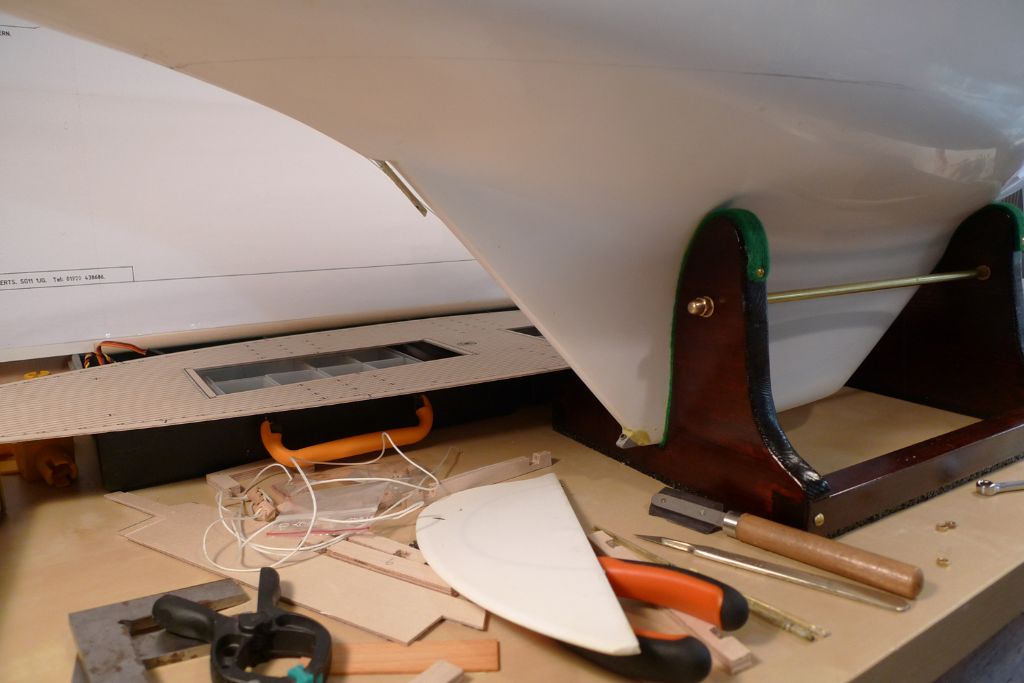
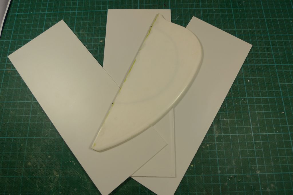
Although the old rudder blade is intact and still in god nick as such, it would be a tad on the tricky tricky side, I think, to get it solidly attached to a new rudder post, so I decided make a new one. To this purpose, three square blanks were cut from 1.0 and 1.5 mm styrene sheet …
… and then joined together with plastic weld at the edges that are to be be discarded after being cut away.
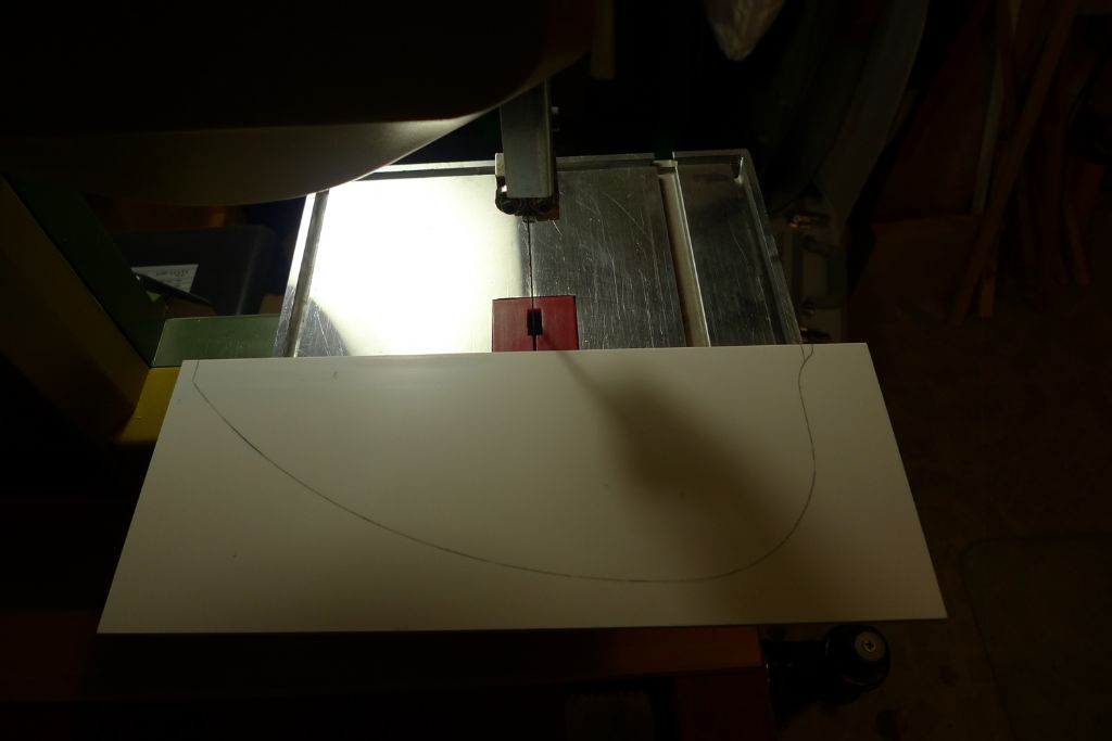
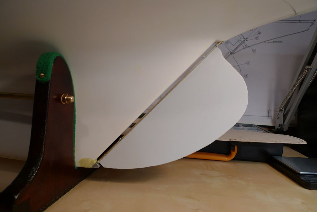
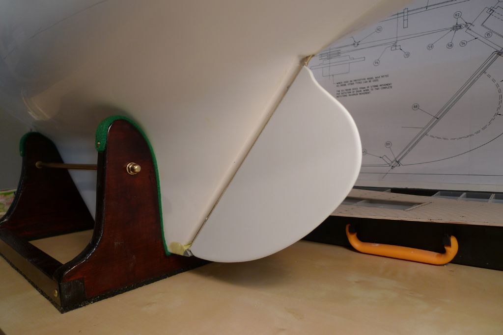
The contours of the old rudder was then traced onto the bundle of blanks, and the shape cut out on the bandsaw. I decided to make the blade shorter by some 4 mm or so at the very top, to make sure that there will be enough play at a later stage to allow me to lift and slot it into the skeg.
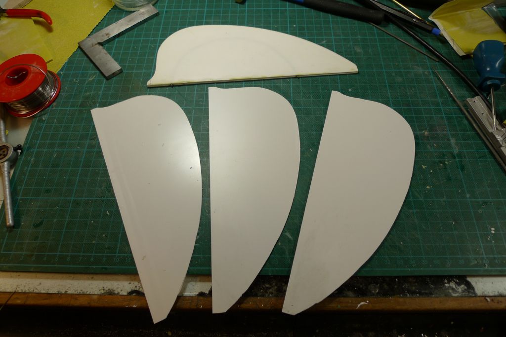
Anyway, once the surplus material was cut away, I had three identically shaped blanks on my hands, one 1.5 mm and two 1.0 mm thick.
To be continued …
/Mattias
15 July 2016 at 21:51 #66575Banjoman
Participant@banjomanNext, I set about the first stages of the rudder post.
This time, I decided to use a thicker wall brass tube than last time round; more specifically one with an inner diameter of 1.5 instead of 2.0 mm, for a stronger post and more material to solder onto.
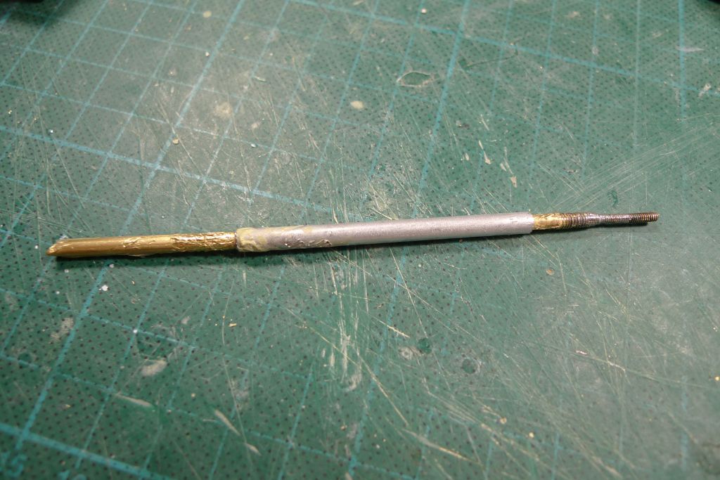
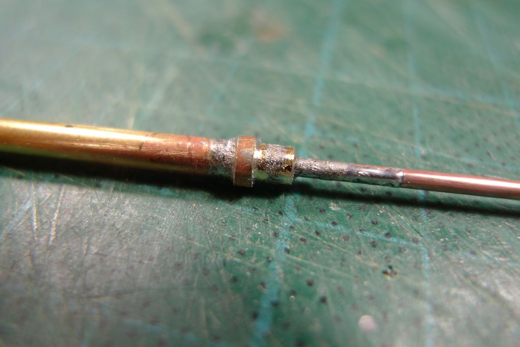
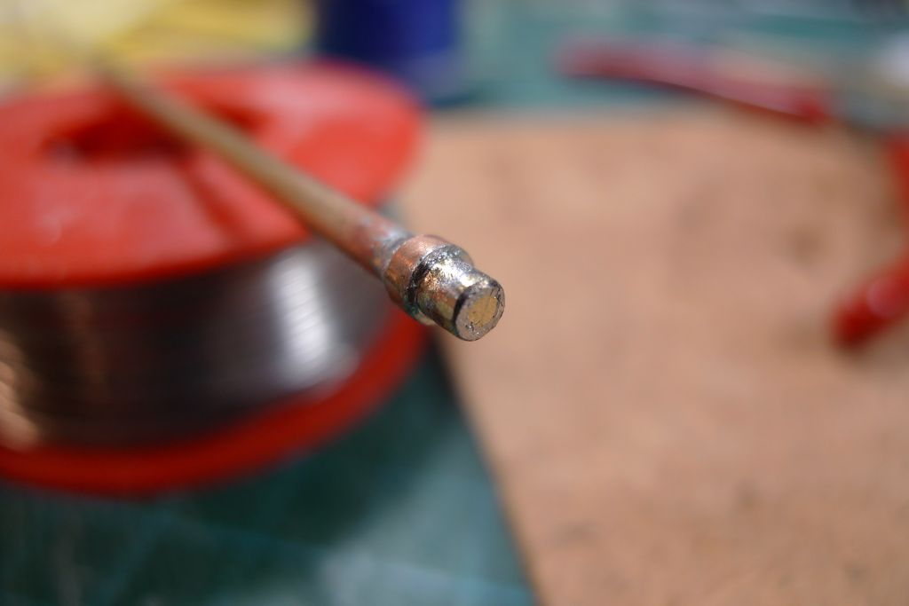
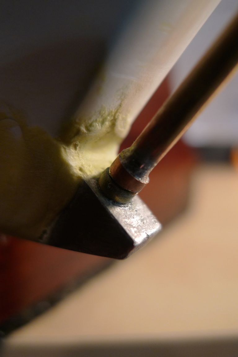
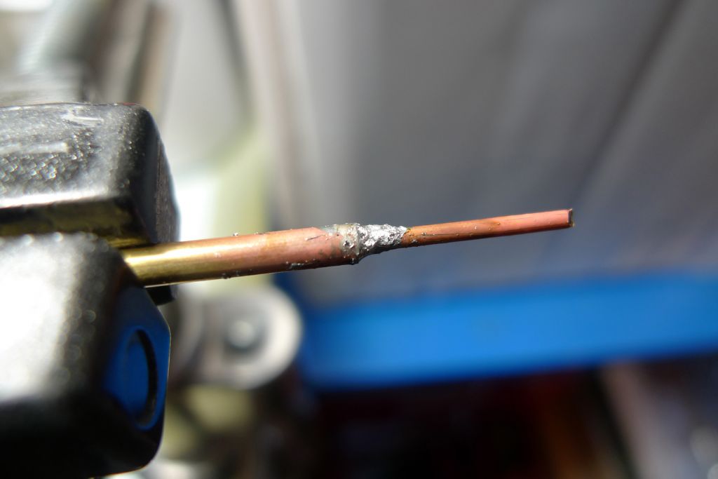
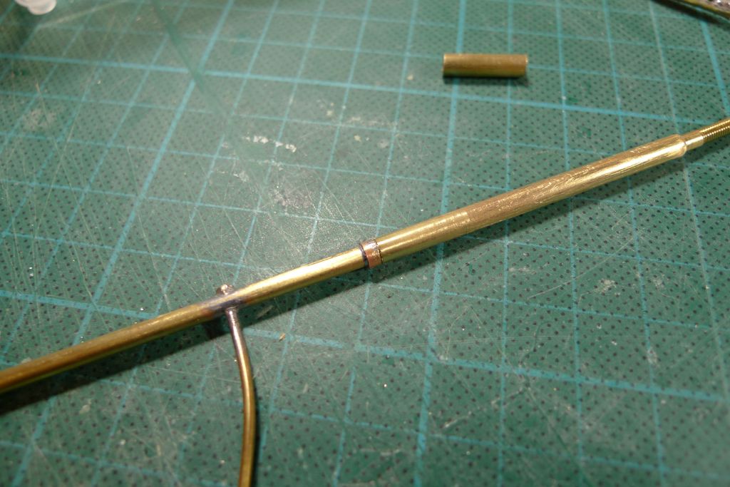
To further reinforce the lower end, a length of 1.5 mm brass rod was tinned and then soldered into the tube, after which the lower pivot bearing in the form of a ring of 4.0 mm brass tube was soldered onto the lower end of the post.
The excess rod was then cut off, the end cleaned up …
… and the pivot bearing dryfitted for checking against the skeg bearing tube.
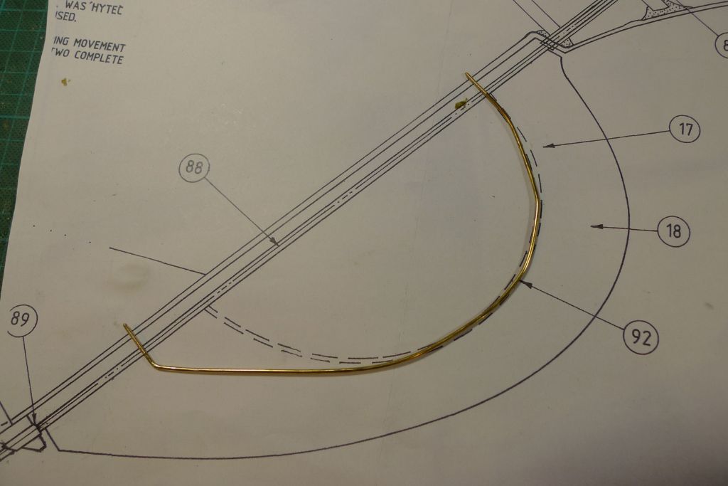
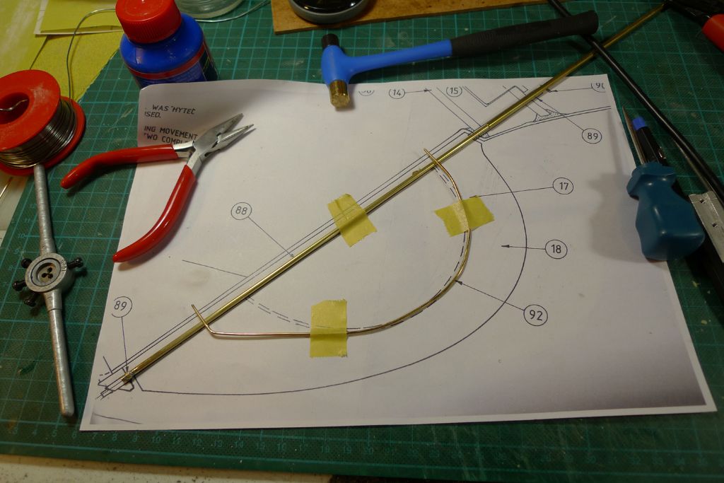
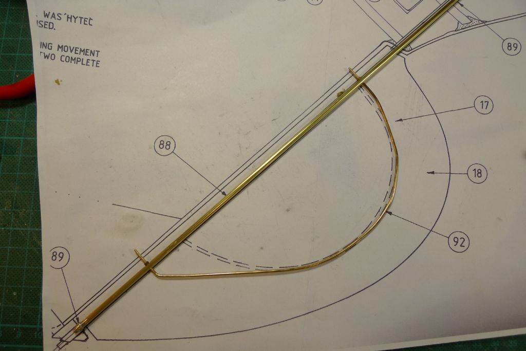
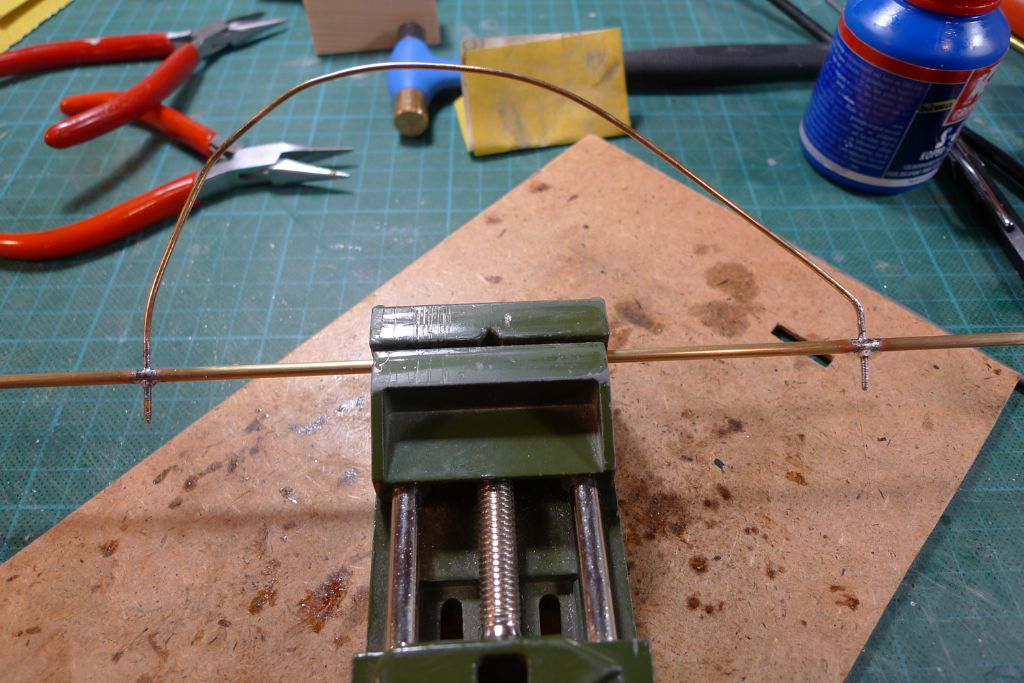
A further length of 1.5 mm rod was then bent to create the blade support, but this time I made it slightly larger than before, to get the stress points a bit further away from each other.
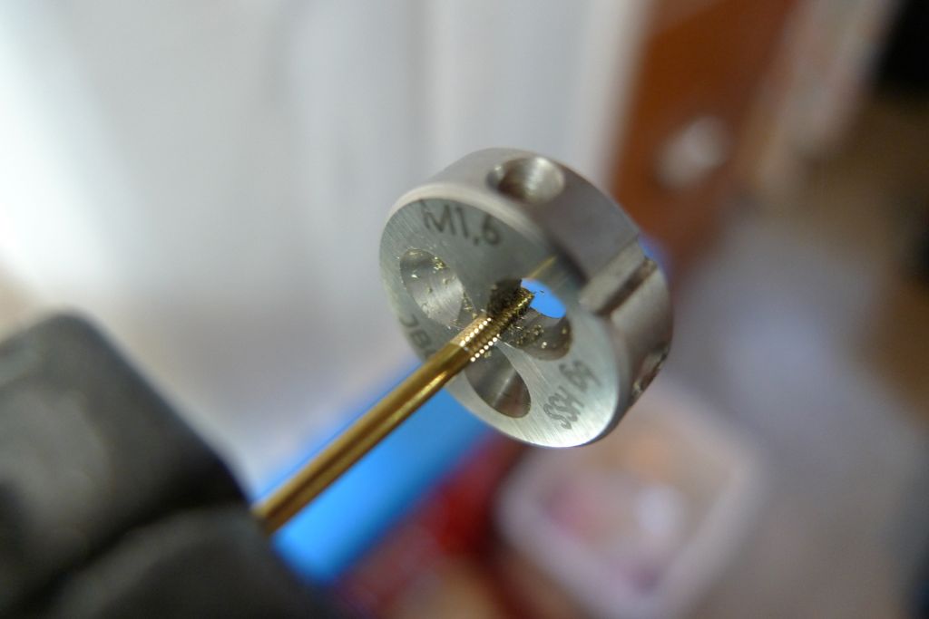
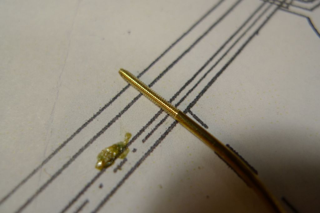
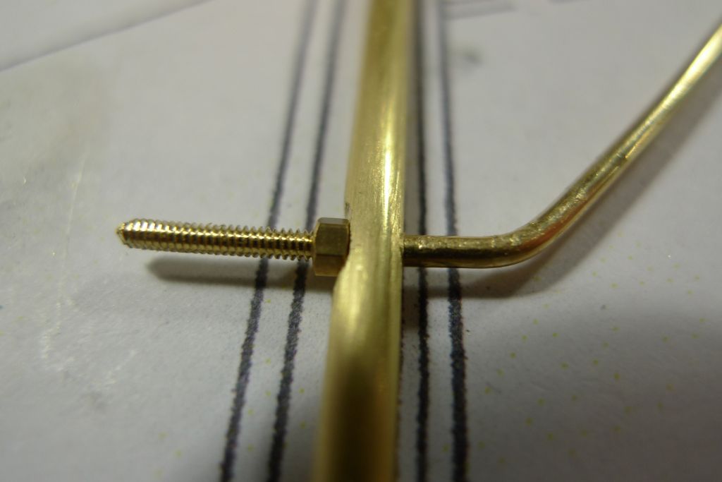
On both ends of the rod, I then cut M1.6 threads …
… up until the point where the rod will go through the post.
The locations where this will happen was then marked unto the post …
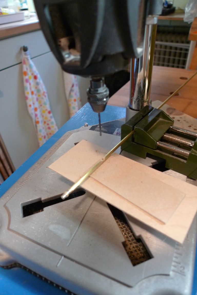
… and filed flat, after which 0.7 mm pilot holes were hand drilled through the first tube wall with a pin vice.
With these pilot holes as a guide, the whole tube was then drilled through in two locations with a 1.5 mm bit set up in the Dremel …
… to let the rod ends through …
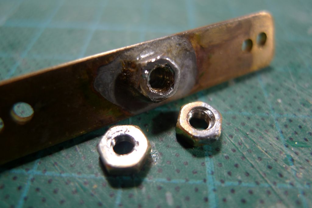
… to be secured against the foremost side of the post by M1.6 nuts.
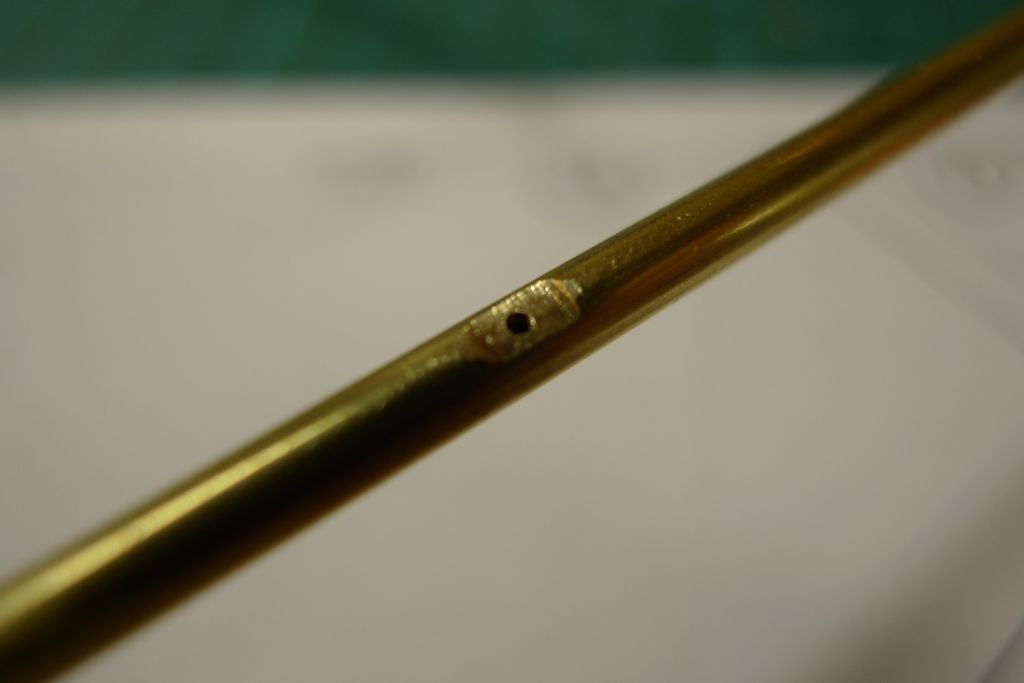
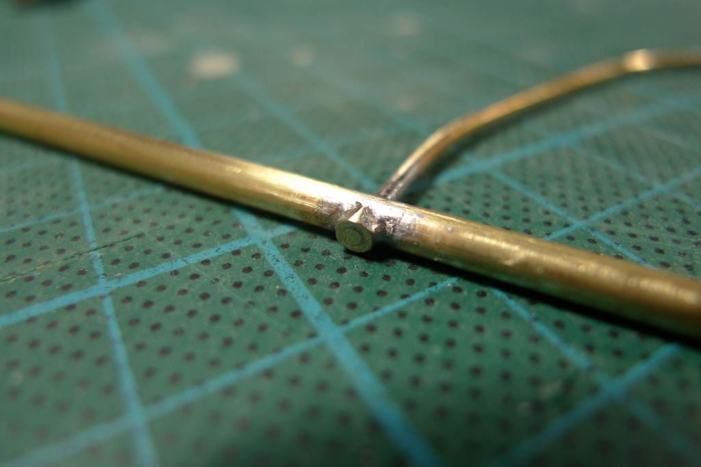
The whole assembly was then soldered …
… the excess cut off, and the ends cleaned up, to create a joint that should be more than strong enough for the forces involved, and which ought to eliminate any risk of the blade coming loose from the post.
To be continued …
/Mattias
15 July 2016 at 22:01 #66576Banjoman
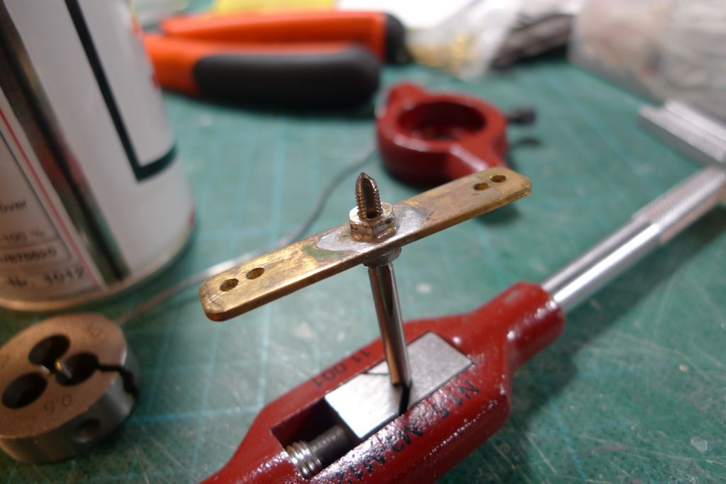
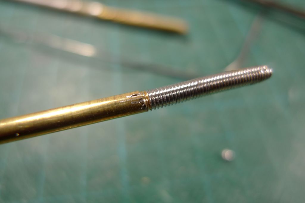
Participant@banjomanThe final job today was done at the other, top end of the rudder post, which was first reinforced in the same way as the lower end, by soldering a tinned brass rod into it.
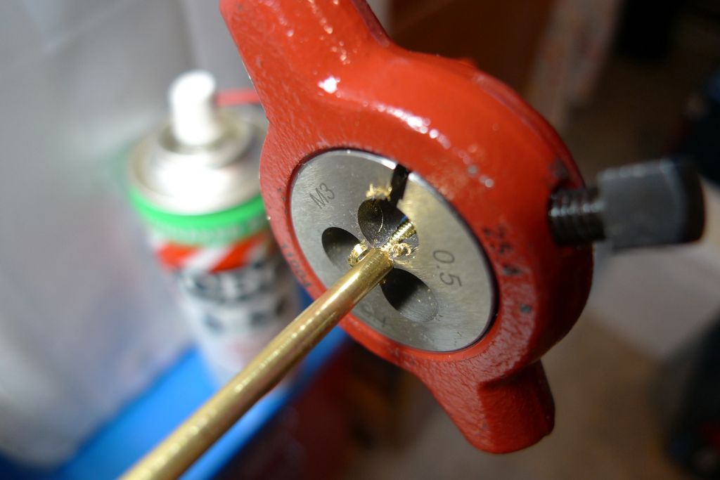
At this end, this was more important, as I went on to cut a M3 thread onto the top of the post, and making the tube for all practical purposes solid reduces the risk that it will twist and collapse under the force of the die. A liberal application of 5-56 as cutting oil further faciltated the job.
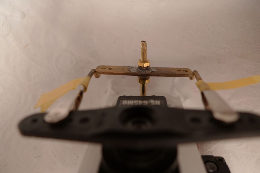
I also cleaned out the internal threads on the rudder yoke …
… and dryfitted it to check against the servo arm.
At the end of the day's work, I thus had an almost finished (the upper pivot bearing still needs to be added) post-and-frame plus the blade blanks ready and waiting for the next build session.
To be continued …
/Mattias
15 July 2016 at 22:42 #66580Bob Abell 2
Participant@bobabell2You are making a nice job of your model, Banjo
But why are you using multi layers of poly for the rudder?
Why not brass?
Just curious
Bob
16 July 2016 at 10:38 #66588Banjoman
Participant@banjomanThanks, Bob

There are actually several reasons why I'm making up the rudder from a styrene sheet sandwich rather than from brass. Let me count the ways:
- It is what the kit instructions tell me to do. While I always read such instructions with a critical eye, and am not afraid to deviate from them if and where I see a reason to do so, I never dismiss them out of hand either, as there is usually a (reasonably) succesful prototype involved, built as per said instructions.
- A solid brass rudder would at 3.5 mm thick be quite heavy, whereas the styrene is nice and light.
- Apart from my mistake the previous time round of not properly anchoring the internal blade loop to the post, this construction is actually very strong. When styrene sheet is layered together with plastic weld, it essentially becomes a solid piece of material, and at 3.5 mm thick is nice and stiff. As it has been welded together around the internal loop, and that loop is now sufficiently well anchored, it cannot come apart except if subjected to very brute force of a degree that I cannot imagine it would encounter on the water.
- To file the hydrofoil blade shape out of solid brass would of course be feasible, but quite a job of work, whereas shaping the styrene thusly is a doddle!
Hope this helps explain my thinking!

/Mattias
Edited By Banjoman on 16/07/2016 10:38:28
Edited By Banjoman on 16/07/2016 10:39:11
Edited By Banjoman on 16/07/2016 10:39:31
18 July 2016 at 16:09 #66614Banjoman
Participant@banjomanWork on the nerw rudder has continued to progress, with the post finished off by the addition of the upper pivot bearing.
A piece of 4 mm brass tube has also been cut to length to make up the new rudder post tube.
In anticipation of fixing the rudder yoke, the threads on the end of the post …
… and inside the yoke and the lock nuts have all been tinned with solder (and of course cleaned up again with die and tap).
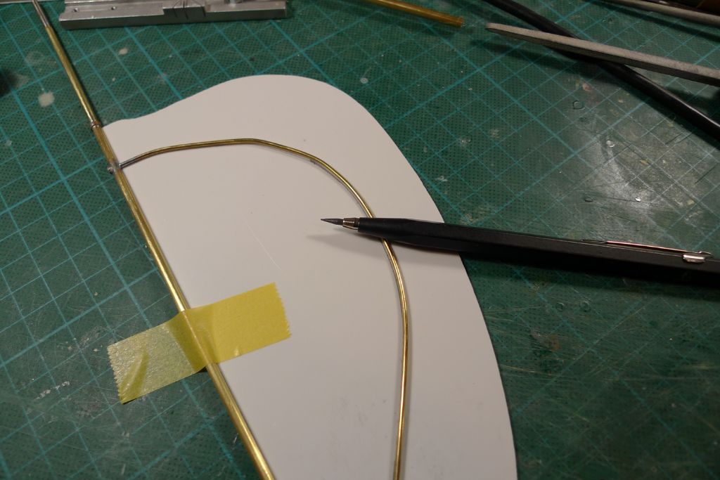
Next, the curve of the blade loop was transferred to the meat of the styrene sandwich, i.e. the central 1.5 mm piece …
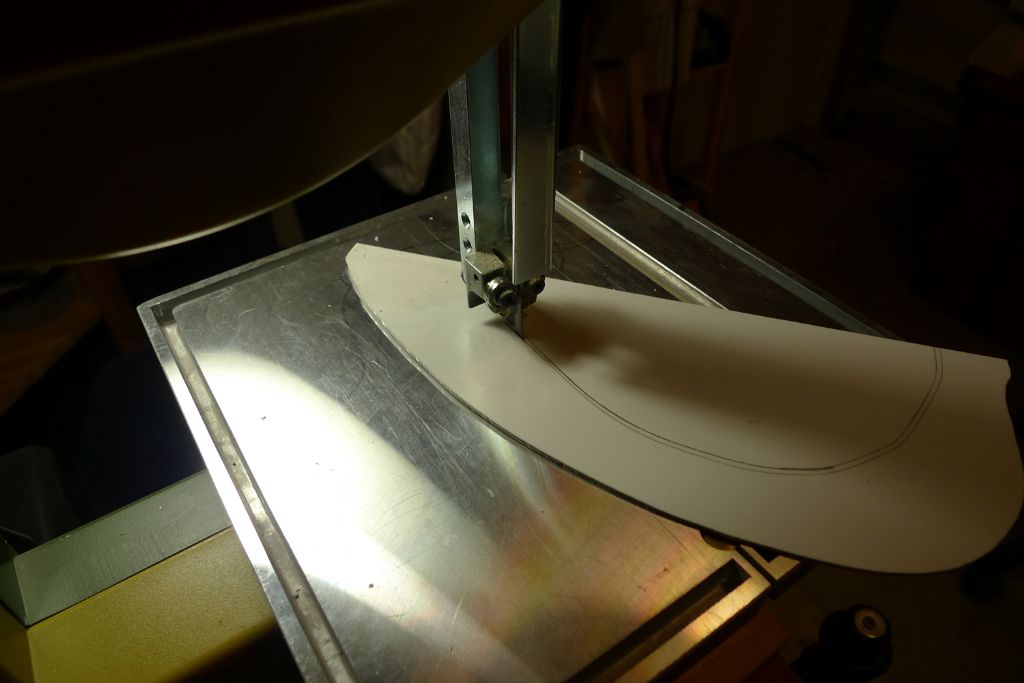
… cut out on the bandsaw …
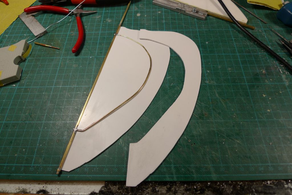
… and trimmed to a nice, tight fit around both sides of the loop.
The rudder balde was then plastic welded together, using fairly liberal amounts of thick Tamiya Cement …
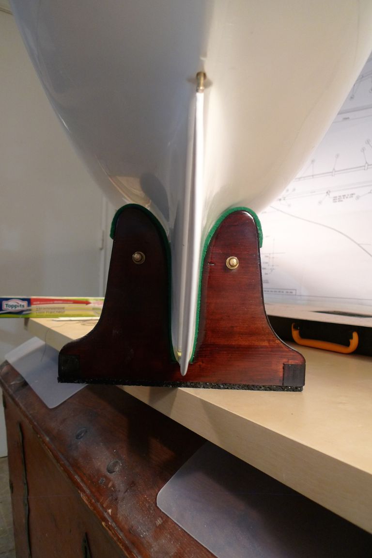
… to produce a quite solid new rudder …
… the aft edges of which were then filed and sanded …
… to a hydrofoil shape …
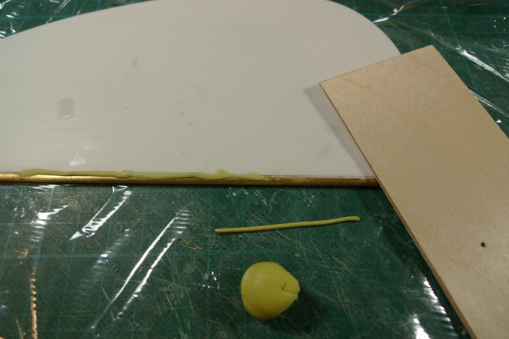
… after which the remaining, minor gaps between post and blade were filled in with thinly rolled-out Milliput (a flat piece of plywood makes the perfect rolling pin) …
… and, after cleaning away excess and smoothing down with a wet finger, set aside for the Milliput to go off.
To be continued …
/Mattias
Edited By Banjoman on 18/07/2016 16:10:27
Edited By Banjoman on 18/07/2016 16:12:23
18 July 2016 at 17:02 #66615Bob Abell 2
Participant@bobabell2Hi Banjo
When you referred to the rudder material as Styrene……..I assumed you meant Polystyrene…….Which is that fluffy stuff, model planes are made from!
Hence my concern…….I now think you are using Plasticard?
I`ve just noticed you are using 1.6mm thread!………Wow!……..That`s only 1/16th in real money!
Say no more
Bob
-
AuthorPosts
- Please log in to reply to this topic. Registering is free and easy using the links on the menu at the top of this page.
Code of conduct | Forum Help/FAQs
Latest Replies
Home › Forums › Sailing Models › Topics
-
- Topic
- Voices
- Posts
- Last Post
-
-
Fairey Huntsman 31
1
2
…
5
6
Started by:
 Chris Fellows
in: Build Blogs
- 14
- 139
-
7 hours, 3 minutes ago
 Chris Fellows
-
Fairey Faun
1
2
3
Started by:
 Chris Fellows
in: Build Blogs
- 7
- 58
-
7 hours, 25 minutes ago
 Chris Fellows
-
Vic Smeed’s Silver Mist
1
2
…
32
33
Started by:
Bob Abell 2 in: Scratch build
- 4
- 822
-
8 hours, 3 minutes ago
 Tony Hadley
-
Fairey Huntsman 28
1
2
…
7
8
Started by:
 Chris Fellows
in: Build Blogs
- 1
- 195
-
9 hours, 33 minutes ago
 Chris Fellows
-
Eezebilt RAF Fire Boat
Started by:
Tim Cooper in: Build Blogs
- 2
- 3
-
10 hours, 8 minutes ago
 Dave Reed
-
Feathered Friends
Started by:
 Chris Fellows
in: Soapbox
- 3
- 7
-
13 hours, 15 minutes ago
 Chris Fellows
-
4D Modelshop
Started by:
Keith Long in: Scratch build
- 6
- 7
-
13 hours, 43 minutes ago
 Chris Fellows
-
John Cobb’s Crusader
1
2
…
7
8
Started by:
 Paul T
in: Scratch build
- 1
- 192
-
1 day, 9 hours ago
 John W E
-
Complex Automata
Started by:
 Colin Bishop
in: Soapbox
- 1
- 1
-
2 days, 11 hours ago
 Colin Bishop
-
RAF Fireboat ID
Started by:
 Dave Reed
in: Collectors’ corner
- 8
- 24
-
3 days, 13 hours ago
Tim Cooper
-
TID steam tug 42″ – PN Thomas drawing enlarged
1
2
Started by:
 Ray Wood 3
in: Scratch build
- 8
- 33
-
4 days, 6 hours ago
 Richard Simpson
-
Lady of Skye (puffer)
1
2
Started by:
 mick east
in: Build Blogs
- 9
- 43
-
4 days, 17 hours ago
 Richard Simpson
-
Building a hull.
Started by:
 mick east
in: Scratch build
- 7
- 10
-
6 days, 16 hours ago
 Ray Wood 3
-
Todays Boating
1
2
…
210
211
Started by:
 ashley needham
in: All things floating
- 84
- 5,252
-
1 week ago
 Colin Bishop
-
Sea Rover Restoration
Started by:
harry smith 1 in: Collectors’ corner
- 4
- 10
-
1 week ago
 Richard Simpson
-
WORKSHOP LIGHTING
Started by:
 John W E
in: All things floating
- 9
- 18
-
1 week, 1 day ago
 Colin Bishop
-
Mayhem Website Down
Started by:
 Colin Bishop
in: All things floating
- 4
- 10
-
1 week, 4 days ago
 Colin Bishop
-
MAGGIE M trawler
Started by:
 sammyk
in: Buy/Sell or Trade
- 2
- 3
-
1 week, 4 days ago
 sammyk
-
meter
Started by:
 Alasdair Allan
in: All things floating
- 5
- 16
-
1 week, 6 days ago
 Chris Fellows
-
River Queen 2”- 1’.
Started by:
Richard B in: Steam powered models
- 5
- 7
-
2 weeks ago
Richard B
-
Deluxe Superphatic Glue.
Started by:
 Colin Bishop
in: All things floating
- 4
- 12
-
2 weeks ago
 Chris Fellows
-
How to add photos to your posts
Started by:
 Colin Bishop
in: Adding Images to Forum Posts
- 3
- 16
-
2 weeks ago
Len Morris 2
-
Cataract
Started by:
Bob Wilson in: Soapbox
- 2
- 4
-
2 weeks, 1 day ago
 Colin Bishop
-
The mighty tug Wattle
1
2
3
Started by:
 mick east
in: Build Blogs
- 10
- 61
-
2 weeks, 1 day ago
 Richard Simpson
-
Clyde Puffer Glenaray
1
2
3
Started by:
 Alasdair Allan
in: Build Blogs
- 6
- 57
-
2 weeks, 4 days ago
 Alasdair Allan
-
Fairey Huntsman 31
1
2
…
5
6
-


