The world's leading magazine for all model boating interests
Galileo – A resurrection
Galileo – A resurrection
Home › Forums › Sailing Models › Galileo – A resurrection
- This topic is empty.
-
AuthorPosts
-
31 January 2019 at 21:14 #80897
 Ray Wood 3Participant@raywood3
Hi Tim,
Glad you liked that one 😁 multi tasking the only way, did I tell you about the steam engines!! Lost cause !
Snow threatened working from home tomorrow -6 this morning
Regards Ray
1 February 2019 at 13:39 #80904Tim Rowe
Participant@timrowe83142Blowing a hoolie her in Mallorca and not much sign of the sun.
Next up on Galileo was to sort out the steering. I am using a standard servo without going to the expense of a waterproof one. Besides which I have plenty in hand from the model aircraft side. Futaba S-148 it is.
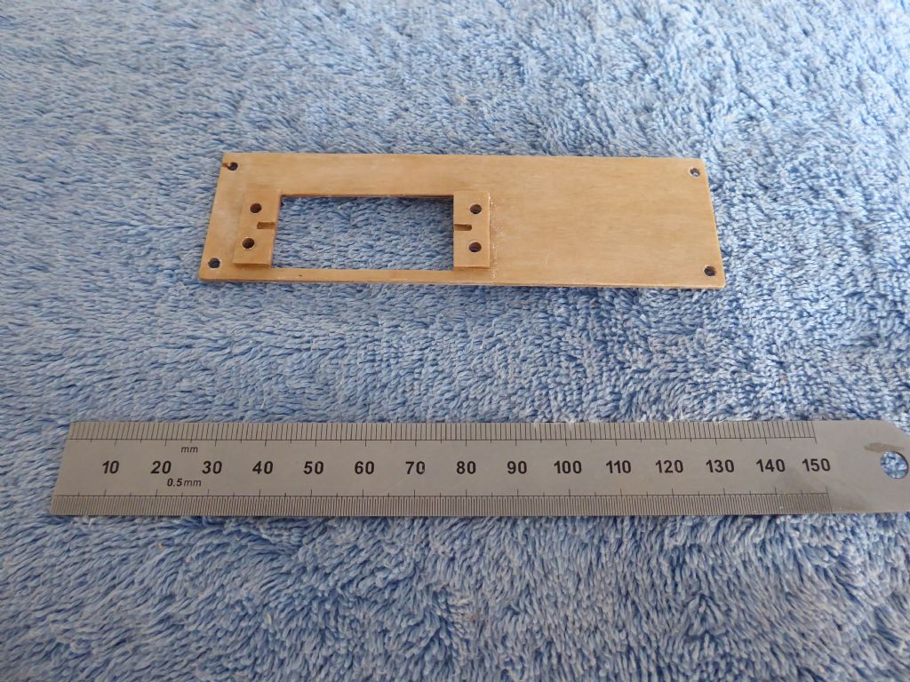
The servo tray is 1.5mm ply and spans the keel support webs on the opposite side to the winch. The loads on the rudder are minute compared with the sails so the mounting can be lightweight.
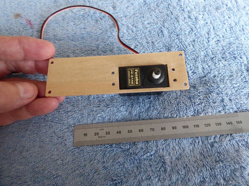
In most boats and especially sailing boats it is best to concentrate the weight in the centre and not at the ends. The steering servo therefore is centrally mounted. The arc of the sail servo arm swipes right across the boat so the steering servo has to be kept low so the arm can pass over the top. The pads are on the underside of the tray so that when the servo is in place, only the very top of the casing sticks out.
Like this. There is no vibration to contend with, like on an IC powered aircraft or power boat so the rubber grommets can be dispensed with. The servo is bolted to the tray and the tray is screwed to the keel webs.
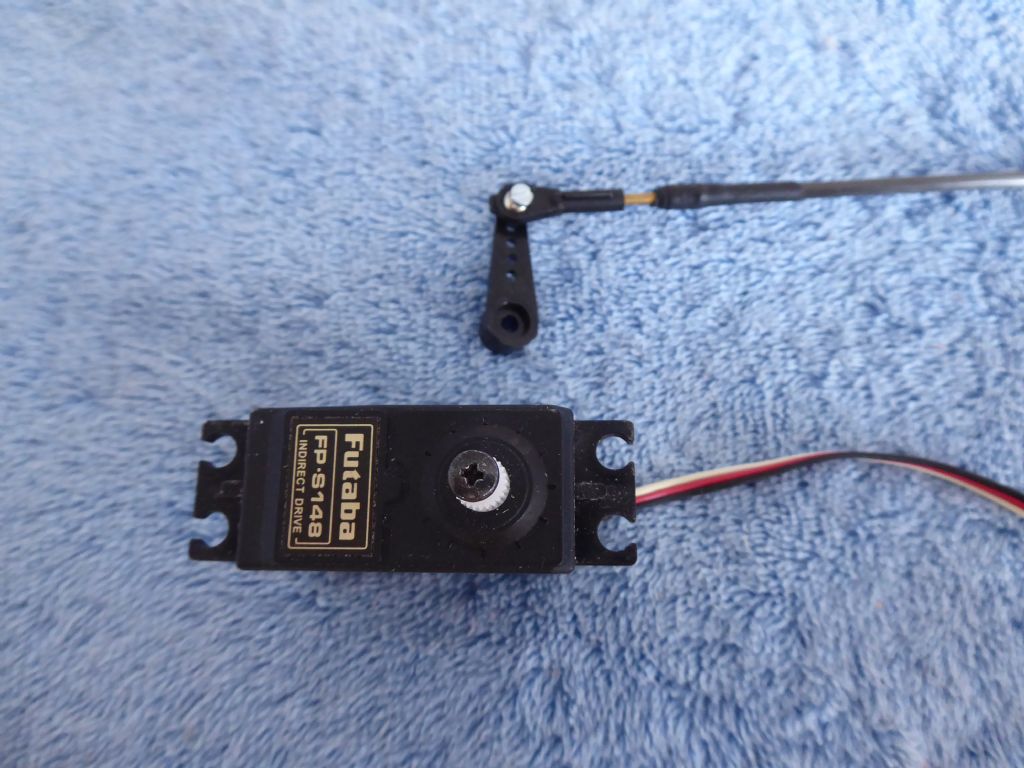
The push rod between the servo and the tiller arm is 4mm carbon tube. This is light and very stiff.
The link is a standard 2mm ball link chosen for its absence of backlash and is connected to the push rod with a 2mm brass stud. The carbon tube was drilled so that the stud would screw in very easily and glued in place with epoxy. The end of the tube was then bound with very thin Kevlar thread to stop it splitting. Unless the tube is spiral wound it has very little resistance to being split by radial forces. A bit like the hoops of a barrel. The ends of the Kevlar thread were sealed with a drop of cyanoacrylic and the whole joint tidied up with a piece of heat-shrink.
The adjustment takes place by winding the ball link on or off the stud.
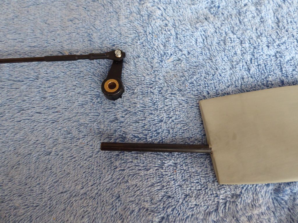
Here is the rudder end done the same way.
The tiller arm was commandeered from a nosewheel steering pack and he brass insert was reamed out to fit the rudder stock. While setting up I have used the supplied grub screw but I don't think the carbon stock will like the point of the grub screw being graunched into it (same splitting reasons) so I will probably drill though and fit a cross pin.
The deck is still a long way from being fitted.
Tim R
1 February 2019 at 20:04 #80905 Ray Wood 3Participant@raywood3
Hi Tim,
Plenty of crossover from aero modelling to model yachting with the radio bits and pieces, I think people must be too busy building to post 😕
Just started tracing some bulkheads for HMS Belfast a long term project I've been contemplating for some years, may have to buy a longer car if I ever finish it 6' 4" long 😃
regards Ray
1 February 2019 at 20:57 #80906Tim Rowe
Participant@timrowe83142Hi Ray
It is very quiet on this forum so I expect you are right. A lot of building going on. I find the whole subject of modelling fascinating across a wide range of interests and could never live with just a single project on the go.
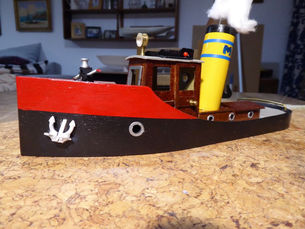
This was a quick Christmas present for my sister in law who is always very generous. Built on the 23rd December and finish painted on the morning of the 24th which is the Spanish Christmas celebration during (a normally quite late) supper.
I am busy making the fittings for Galileo and trying not to buy off the shelf as 50 years ago everything was home made as the pocket money didn't stretch to much.
Tim R
1 February 2019 at 21:49 #80907 Ray Wood 3Participant@raywood3
Hi Tim,
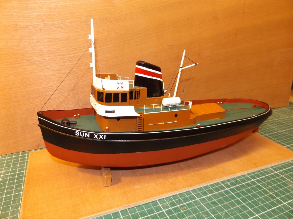
That is a super present, lots of character, I'm trying to get back to the pocket money type kits from my childhood, when the Keilcraft catalogue was full of so many dreams, I spent the rest of my life (so far) trying to build them all 😁 I think I'm regressing. This is my take on the little tug Otter for younger modeller as a free plan in Model Boats published last year, currently working on my version of Curlew ☺
2 February 2019 at 07:40 #80908Tim Rowe
Participant@timrowe83142Hi Ray
Tugs do have character and attitude and make great modelling subjects.
Wonder if you could do me a favour. If your DG95 uses a lever arm sail servo, could you post a couple of photos of the sheeting arrangements. Left to my own devices I think I could easily over complicate things.
Oh! and just how many projects are you running at the moment?

Tim R
2 February 2019 at 09:10 #80909 Ray Wood 3Participant@raywood3
Hi Tim,
Maybe 8 or 9 but I don't finish much 😃the DF95 has a drum winch & Running line on the deck tensioned with elestic
Will take some pictures of the lever arms in my barge, could be useful they are 2 to 1 purchase with a pulley on the arm to double the travel for the main sheet .
Will be Monday as we only have tablets at home, and the photos aren't that good from them.
Regards from the still freezing uk
Ray
2 February 2019 at 21:38 #80919Eddie Lancaster
Participant@eddielancasterHi. Ray, Tim, maybe like me they look but don't post, I check the forum at least twice a day, look at what is being said and then put anything I find interesting or useful into the 'must remember that' file.
I have found this thread very interesting Tim, with lots of ,to me anyway, novel ideas, please keep them coming.
Regards to you both.
Eddie.
Edited By Eddie Lancaster on 02/02/2019 21:39:16
3 February 2019 at 12:10 #80935Tim Rowe
Participant@timrowe83142Thanks Eddie
I am enjoying the build and also the blog. This time I am trying very hard to keep to this one project (there are plenty waiting) and get the boat on the water as soon as possible.
Actual construction has slowed to a standstill while I make up what is effectively a kit. This is a hangover from the model aircraft construction where I like to have everything to hand to dry fit before committing to glue. It is very tempting to put the deck on but not just yet.
Some while ago I bought a GoPro camera and as yet it has not been used. I have seen some onboard videos on RC yachts and they were interesting. I have decided to have a go with Galileo.
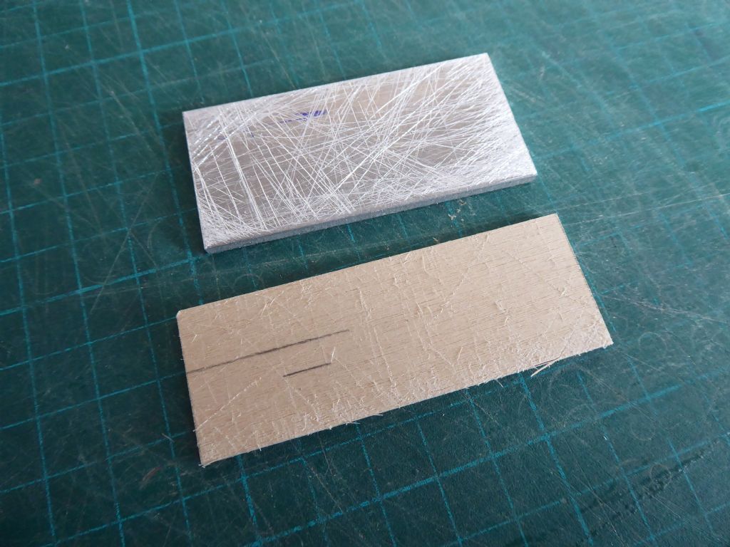
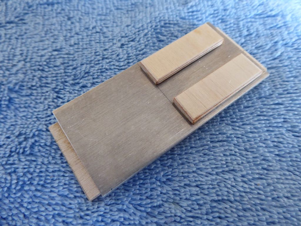
The camera will be pole mounted and removable so the first thing needed is a solid base. The aluminium will be the tapping plate with four M3 tapped holed and the ply is 2.5mm matching the thickness of the 2.5mm balsa subdeck. This is to give the deck mounting bracket something to be tightened up against. The balsa would crush but the ply won't.
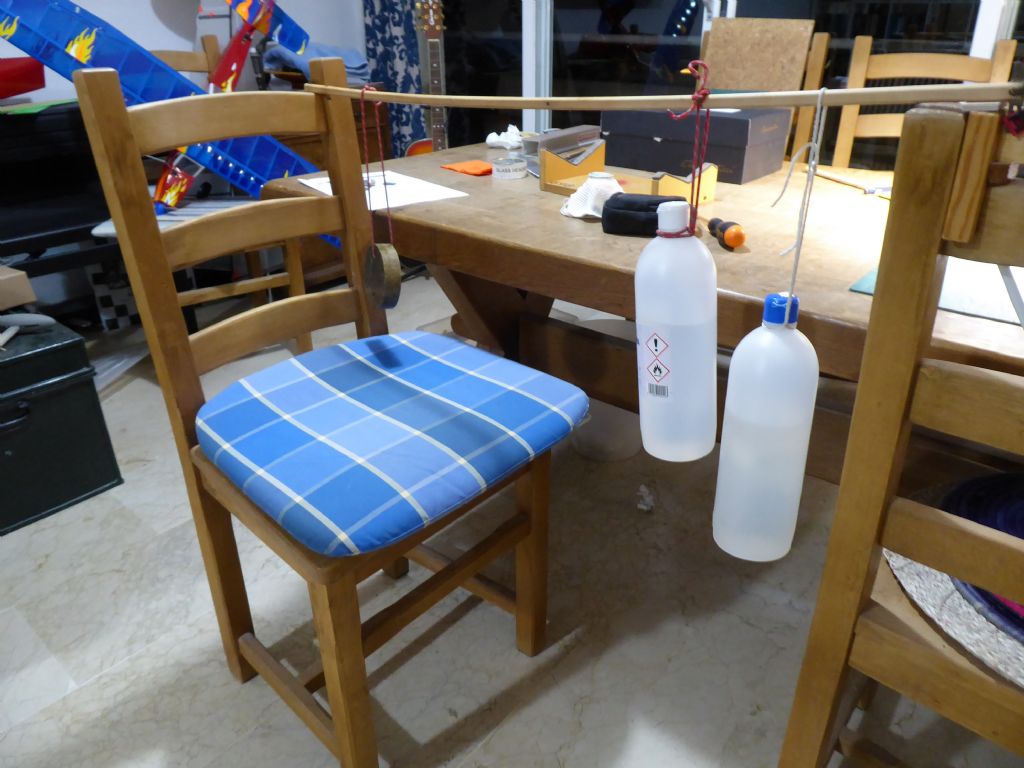
The ply and the aluminium is scored to create a good key and the aluminium was degreased with alcohol just before gluing. In most cases I prefer alcohol to acetone because of its lower rate of evaporation. Acetone is so quick that the solvent can dry on the cloth with then re-contaminates the surface unless the cloth or paper towel is turned to a clean section very frequently. With alcohol the surface dries quite quick enough. Pus I prefer the smell!
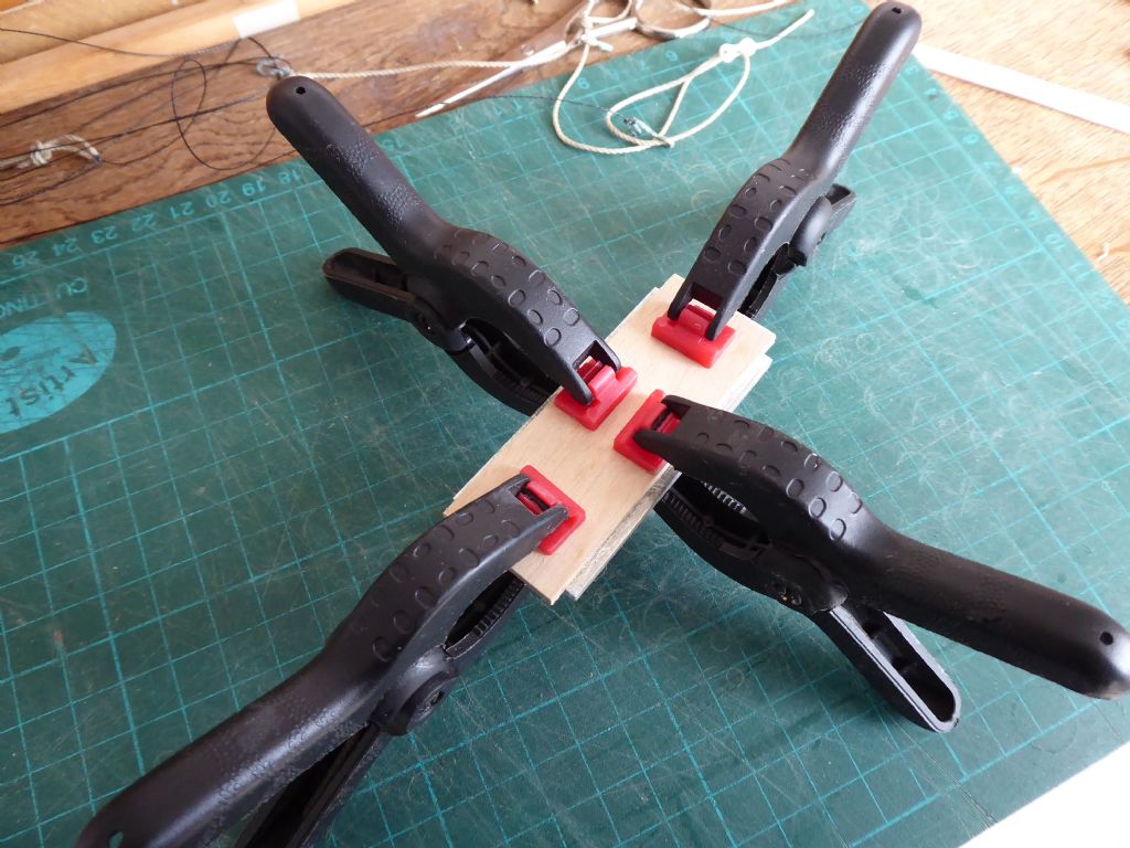
Plenty of clamps as usual.
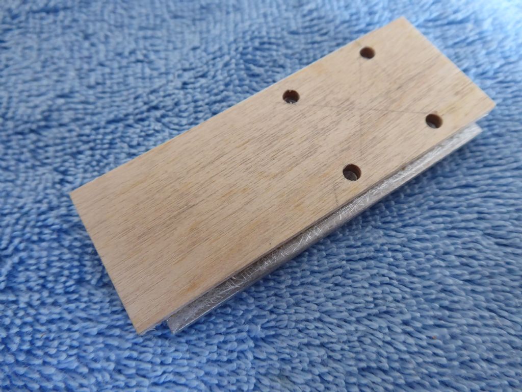
The aluminium fits exactly between the deck beams and the ply is slightly longer so it goes over half the deck beam width. The aluminium is slightly wider than the ply which will give the subdeck something to land on rather than having a free edge simply butting against the aluminium.
Here the four mounting holes are drilled and tapped with clearance holes in the ply.
On the underside, two pieces of ply were glued so the tapping plate will not allow water to leak into the hull if the fastenings are loose or not installed. When not using the camera I will probably cover the holes anyway with a self-adhesive deck patch.
It now goes into my box of sub-assemblies making up the kit.
Tim R
3 February 2019 at 18:00 #80941Tim Rowe
Participant@timrowe83142Turning my attention now to the rig. Most of this can be original as the mast, boom and sails survived. The rigging wires did not as they were twisted and soldered wire used for control line flying. I am using new running rigging and because I my understanding of boats is better now than it was, there are a few refinements so some extra fittings to make.
All the visible fittings will be brass in keeping with the original and as shown previously I have managed to keep the chainplates.
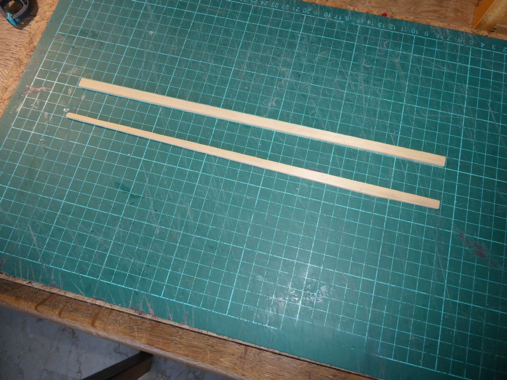
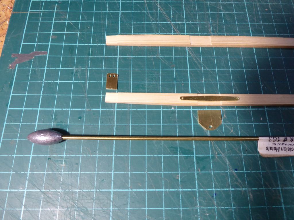
The jib boom did not survive. It was made from obeche whereas the mast and boom were made from dowels which is much harder and stronger. I also made a mistake in the original by having the jib pivot too far forward. This meant that the leech of the jib could not be held tight enough.I didn't have any suitable dowel but I did have some very fine grained spruce to use instead. The original fittings were slotted through the boom on the centerline. I can't remember how I did that but it must have been laborious. Instead I have made the boom in two laminations so I can make a shallow groove in both halves. When they come together I have the slot. It was easier and more accurate.
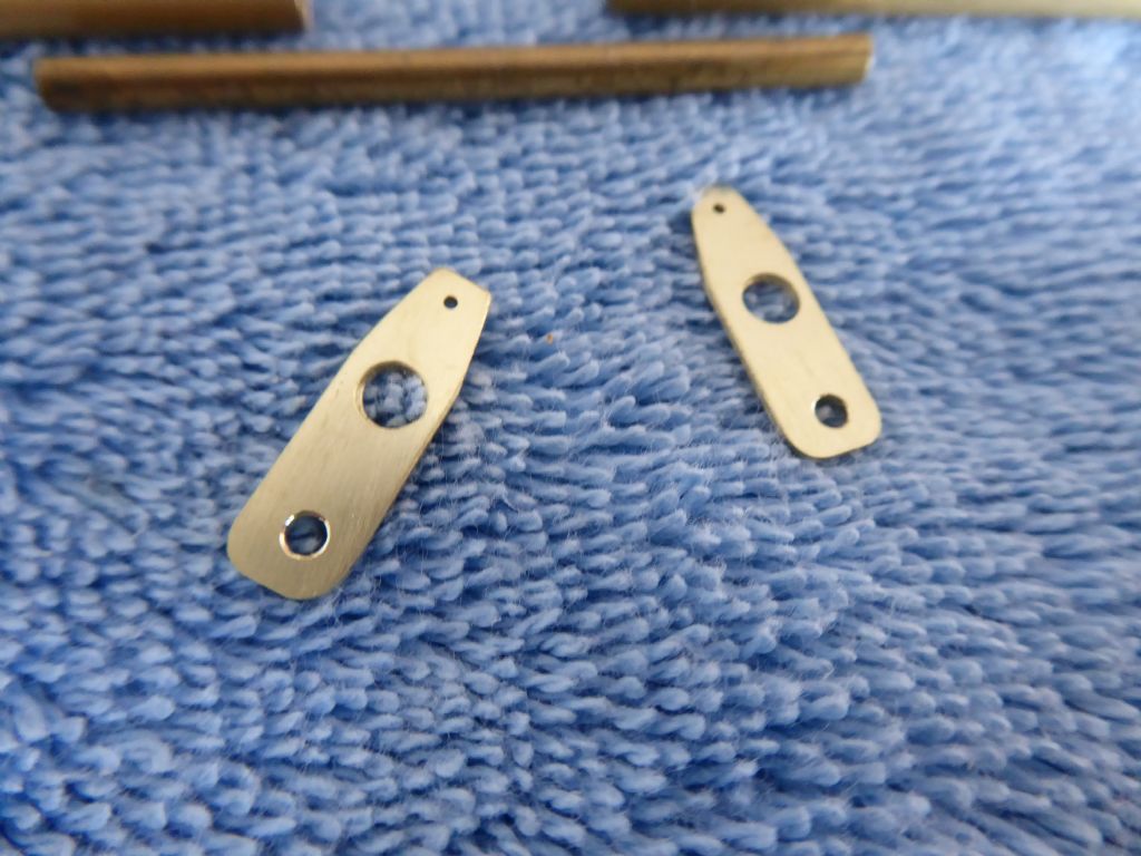
Here are the fittings for the fore end of the jib boom. They are cut from 1mm brass sheet and here you can see the grooves that form the slots. The counter balance is a lead fishing weigh cyano glued to a piece of brass tube.
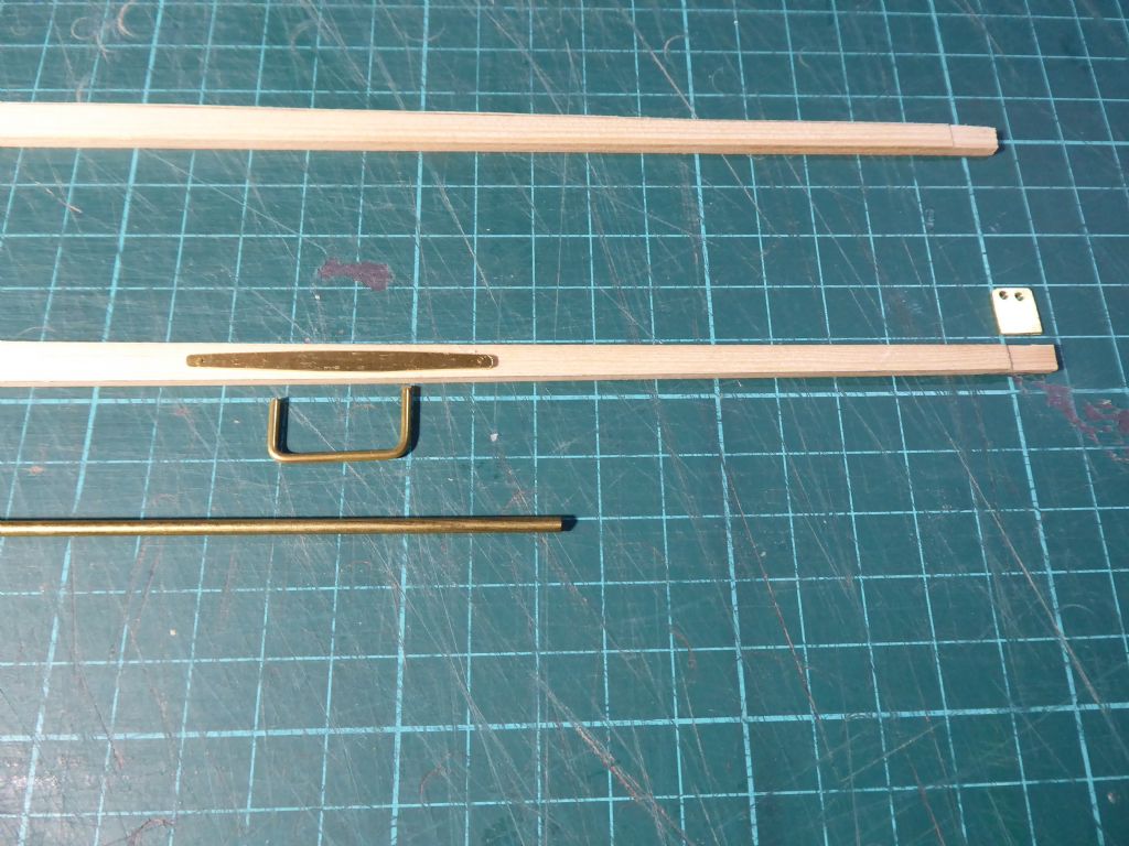
The hoop for the jib sheet and is the same distance from the pivot as the existing main boom. This is to make sure that the main and jib sheet in at the same rate from the single sail servo.
The tapered brass plate will go on the top of the boom and the tails of the hoop riveted over it. A brass pin at each end holds it flat to the boom. Later on there will be hoops at the fore end of the boom that will allow the counterweight to be moved backwards and forwards for fine adjustment.
The fittings are cleaned up first with files, then 240 grit to take out file marks and scribe lines. They are then cleaned with 400, 800 an finally 1200 wet or dry and fitted in that condition. Finally, when all assembled and the spars varnished they will be brought to a shine with metal polish.It is slow work but very satisfying.
Tim R
4 February 2019 at 10:56 #80951 Ray Wood 3Participant@raywood34 February 2019 at 11:19 #80954
Tim Rowe
Participant@timrowe83142Hi Ray
Most helpful thanks. Do you use elastic to keep some tension on the sheets? I am concerned about the sheet snagging the steering servo. I will be posting a photo to show what I mean.
Some lovely work has gone into that model.
Tim R
4 February 2019 at 11:35 #80957 Ray Wood 3Participant@raywood3
Hi Tim,
I'd like to take credit for the build, she is a beautiful but built by Peter Simmonds of the Isle of White. I jumped at the chance of owning one of the prototypes he built for the Traplet Plans. The rig is so well done, he was a boatbuilder by profession and knows his stuff, I think at last count he has built 12 Veronicas, he says 2 1/2 months is the average build time

No elastic involved, you could put a Perspex sheet over the steering servo ?
Regards Ray
Edited By Ray Wood 2 on 04/02/2019 11:37:01
4 February 2019 at 12:07 #80959 Chris FellowsParticipant@chrisfellows72943Posted by Eddie Lancaster on 02/02/2019 21:38:41:
Hi. Ray, Tim, maybe like me they look but don't post, I check the forum at least twice a day, look at what is being said and then put anything I find interesting or useful into the 'must remember that' file.
I have found this thread very interesting Tim, with lots of ,to me anyway, novel ideas, please keep them coming.
Regards to you both.
Eddie.
Same here Tim, watching with interest. I'll only post if I'm asking a question or have something worthwhile to say. As it's effectively a build thread many folks probably don't like adding too many comments.
Chris
Edited By Chris Fellows on 04/02/2019 12:09:10
5 February 2019 at 14:23 #80980Tim Rowe
Participant@timrowe83142A quick job that I had to get around to sometime – although I thought it was. The original mast has, over time taken on quite a considerable bend. It is bowed forward in the middle by about 20mm. The sails were not cut for this amount and so it had to be corrected. I am not sure of the cause but down the aft side of the mast there is a wire jack-line that the sail hooks onto. This was intentionally tight but had rusted away when I finally unpacked it.
My first attempt at straightening and believe you me there is quite a lot of weight hanging there. I left this for a week but it did nothing whatsoever. Not even 1mm which was a bit of a surprise.
Plan B was the hot air gun I use for shrinking film on model aircraft (also very useful for applying heat-shrink sleeves). I clamped the air gun pointing vertical taking care not to block the inlet and using two hands, worked the mast up and down over the heat until straight. Even this took quite some time and it was necessary to get the wood quite hot to touch. My biggest concern was not to scorch the timber as in keeping with the original, all the spars are varnished.
Even so the wood had a small amount of memory and over a couple of days, a very small curve crept back in. Over the heat again for some more tweaking and this time a slight over bend was put it. When the mast cooled it was back straight again and has remained so in the couple of weeks since I worked on it. The jackstay system will be re-used as it worked very well and saves having ties right around the mast. This time though I think I will arrange it so that it can be slackened off when not sailing.
Tim R
6 February 2019 at 11:40 #80985Tim Rowe
Participant@timrowe83142All the mast fittings survived except the spreaders. Originally this was a brass tube glued into a drilled hole in the mast. They got bent a few times in storage and broke off. They were also imperial at 1/8" diameter so my new material at 3mm was a bit sloppy in both the mast and the fittings for the lower shrouds.
So I made a complete new set. There is a short length of tube that is a close sliding fit in the spreaders. This is glued into the mast in a new hole because originally I had the spreaders a bit too high. This will stay fixed.
The fittings for the lower shrouds slide over the central tube and are glued and pinned into the mast.
This closeup of the lower shroud fittings shows the generous countersinking of the hole for the rigging to make it kinder on the wire.
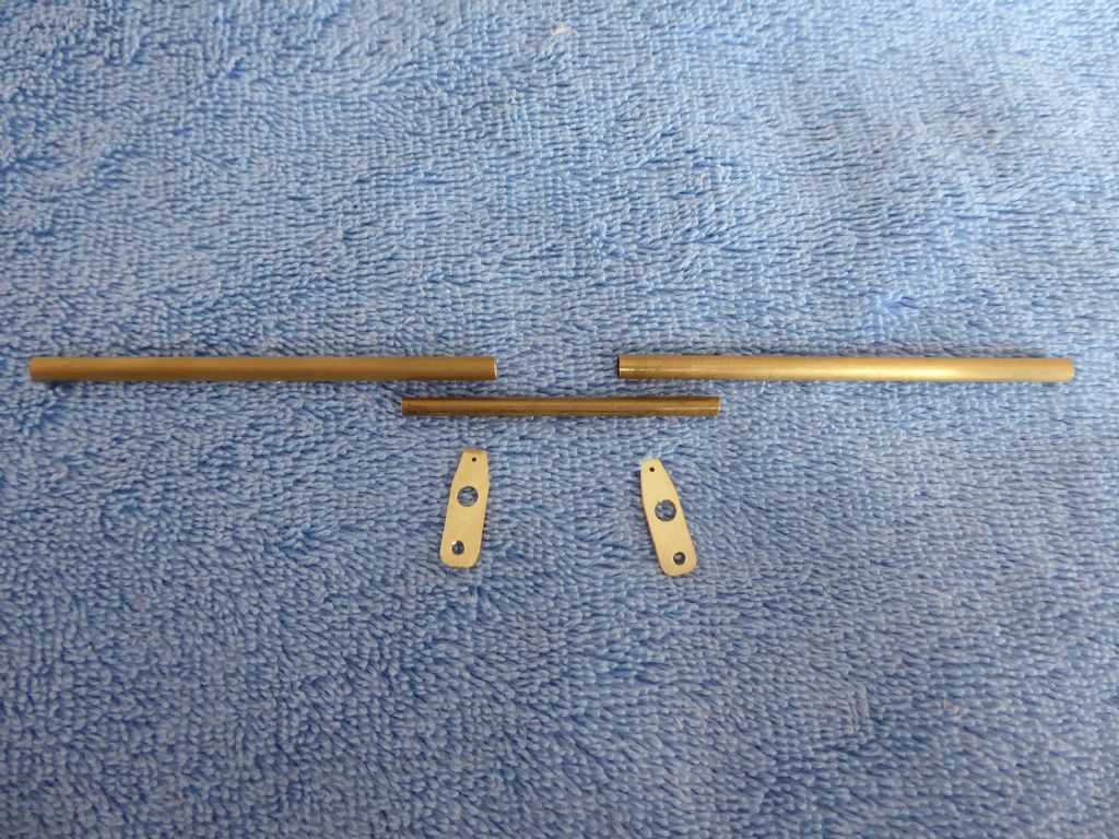
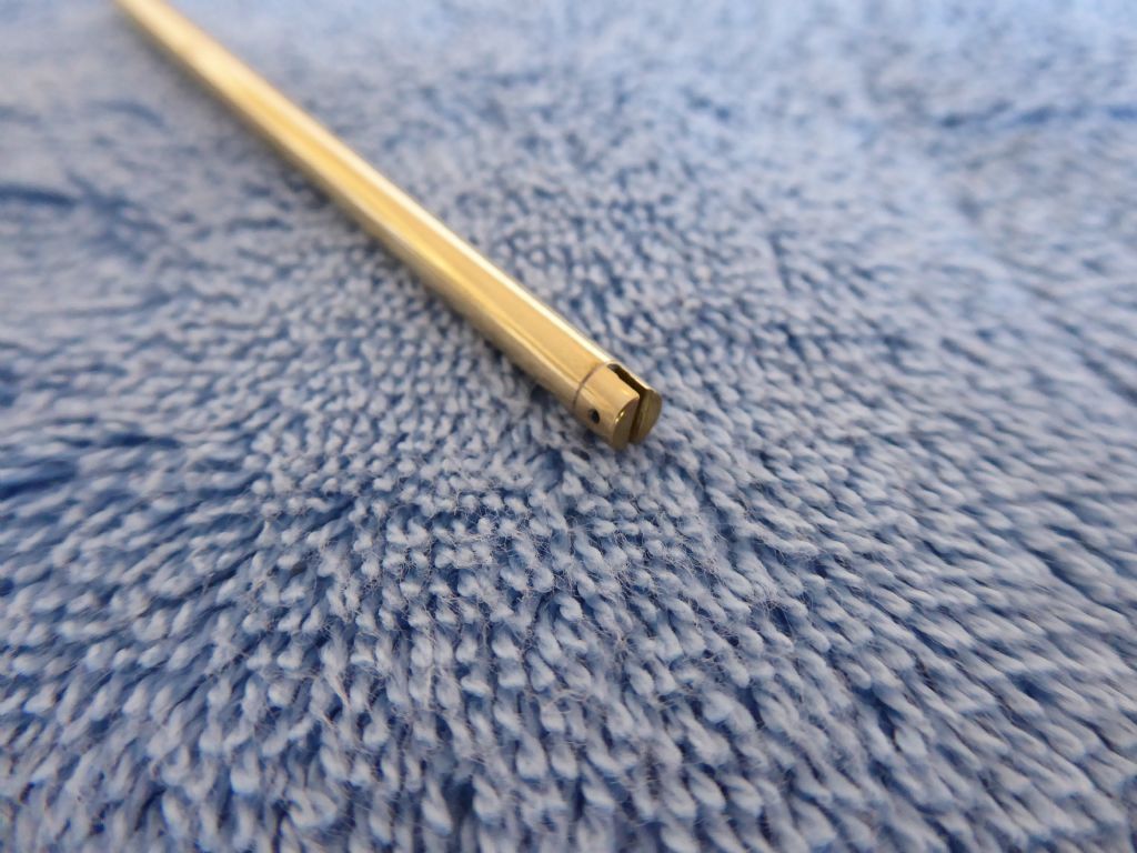
The outboard ends of the spreader tubes are fitted with a slotted cap. This was turned up on my Proxxon lathe and soldered into place. To mark the position of the slot exactly in the centre of the cap I stopped the lathe and used the facing tool to score across the end using the cross slide. Of course this relies on the tool being accurately set on the centerline in the first place.
The slot will accept the cap shroud the cross drilled hole will take a brass panel pin to stock the wire from falling out of the slot if it goes slack.Now for long term storage or transport, I can remove the spreaders leaving the short middle section which is not so vulnerable.
Next job on the lathe is to turn up the parts for the kicking strap. It is sketched up in principle and I just have to find the suitable bits of brass to make it from.
Tim R
6 February 2019 at 22:42 #80989 Ray Wood 3Participant@raywood3
Hi Tim,
That's good metalwork, I enjoy working with brass it is ideal for boat fittings, I never got on with stainless steel 😮
Keep up the good work
Regards Ray
7 February 2019 at 19:48 #80997Tim Rowe
Participant@timrowe83142Hello Ray
Yes brass is quite nice to machine as it is best done dry. At least you can see what you are doing. The only downside is the very small chips making up the swarf get everywhere.
I have done a lot of stainless steel work in the past. Our business used to make many of the M S Gibb yacht fittings. The secret was correct tool geometry, rigid machines with plenty of power, quite heavy feeds at not excessive speed and plenty of flooded coolant. Dwell anywhere and you are heading for trouble. This was in 316 stainless which is not the easiest but not the hardest either. The machines were bar feed auto capstans with air logic controls. Martonair who shortly afterwards went bust as CNC came in.
I have also machined quite a lot of Nickel Aluminium Bronze which is quite stringy and tough. Similar techniques as for stainless. This was a contract I had to replace all the original galvanized wrought iron fittings on the Fife Schooner Altair. I took the originals and converted them into patterns "growing" them a bit to allow for shrinkage and machining allowances and then had them cast. The turning I did on a big Colchester (lovely tool) including some very big threads. Not hugely scary though at 30 RPM. The fittings all then went for polishing. A much more skilled job than many think. This was in the mid-eighties just my fittings cost £30,000. Imagine that in today's money.
A lot of these big yachts lost their keels to the war efforts and got scattered all over Europe and the far east as bullets. After the war Altair's keel was replaced in sections as there was no foundry nearby that could do it in one. It was a nice job though as each section was tenon jointed into the other. My brother in law constructed a railway so that the old sections could be wheeled away from the boat. The lead then went down to Henry Irons in Cornwall to be cast back in one piece. The railway served to get it back in place. I can't remember the weight but you wouldn't want it on your toes! The one piece keel was done to get back to the original specifications for longitudinal strength.I kept in touch with the captain who then went on to be the master of Adix, the big three-masted schooner owned by the Spanish family who were the major shareholders in Santander Bank. The day boat for Adix was another Fife call Lady Anne. I went onboard both boats in Valencia about six years ago. Both would make great modelling subjects and I know Altair is kitted somewhere. Happy days.
Tim R
7 February 2019 at 21:22 #81000 Ray Wood 3Participant@raywood3
Hi Tim,
Well I asked for that one didn't I 😀 heavy duty proper boat stuff !! Well my humble efforts in loco building have just been done for fun , with one exception, I built a loco for cash for a guy when Canary Wharf finished, I didn't go back into the workshop for a year after that 😮 i 've made up for it since 😀
Regards Ray
8 February 2019 at 12:53 #81005Tim Rowe
Participant@timrowe83142A bit more metalwork done with the mast step.
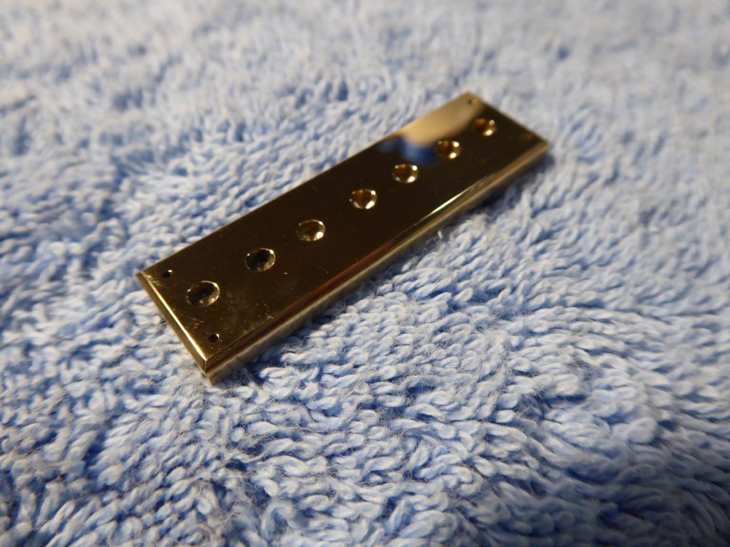
Made from two pieces of brass. The top piece is drilled through to accept the pin at the heel of the mast. The bottom piece seals the holes and stops water getting down onto the subdeck. The two pieces then soldered together and cleaned up. The four holes in the corners are for panel pins.
I am getting near to the end of the polishing. While the results are pleasing, I hate the process because it is so messy and very easy to contaminate other surfaces. One thing when polishing it to leave de-burring the drilled holes until afterwards. Polishing tends to draw the edges of the holes so they look oval and ill defined. Cleaning with a larger drill or a countersink after polishing makes a much neater hole. This is noticeable even on small holes but specially so on full sized stuff where a drawn hole looks horrible.
Tim R
10 February 2019 at 12:18 #81033Tim Rowe
Participant@timrowe83142Now working on the sheeting system and it is a bit of a leap in the dark. I want to avoid lines on the deck so hopefully everything is going to happen inside. The other point concerns the use of a lever type sail control servo whether the movement is not linear. With a drum type winch you can use a running line tensioned with elastic and attach the sheets to the running line. The drum will a constant rate at any stage of the travel.
I think friction may be my worst enemy but anyway I am going to give is a go. The only open holes in the deck will be at the sheeting posts. I am using one for the main and one for the jib.
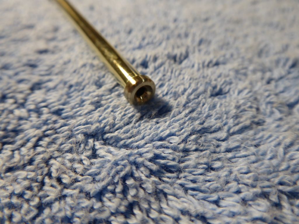
This is the bottom end of a sheeting post made from 5mm brass tube. The end is flared to provide a lead for the sheet itself. The flare was made with a variety of pointed tools with frequent annealing of the tube. The annealing is done by heating the end of the tube to red heat (being careful not to burn it) and rapidly quenching in water. Brass work hardens quite quickly and so frequent annealing is required to avoid splitting.
This is the top of a sheet post fitted with a bush with a flared exit again to create a fairlead for the sheet. The bush is a sliding fit and will be Loctited in place later on.
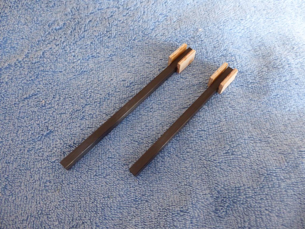
These are the carriers for the mast posts. 6mm square sectioned carbon tube with ply boxes to hold the sheet posts. Here the photo shows the two side pieces of the box.
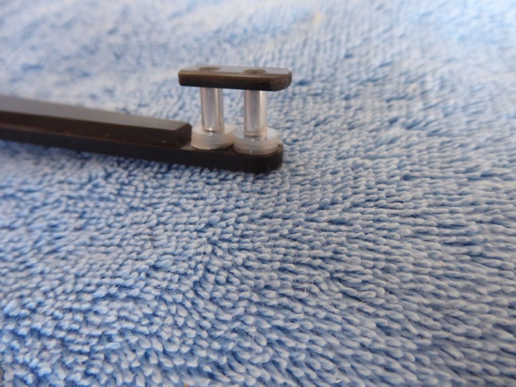
The posts locate on the hull bottom and supported at the top by a deck beam.The servo arm was supplied as a plain arm with two holes at its extreme. I didn't have any suitable blocks so in keeping with trying to make as much as possible I fitted these two aluminium rollers running on carbon fibre rods. The cap is an off-cut piece of carbon fibre strip and the nylon washers will guide the sheets above the raised section of the arm.
Nearly ready to see if it all works.
Tim R
14 February 2019 at 08:33 #81074Tim Rowe
Participant@timrowe83142The first failure didn't take long to arrive. The rollers on the end fitting were too high and created a twisting moment on the arm. The rollers were shortened to 3mm height but when I pressed the end cap in place it split. The material is very strong along the length but surprisingly weak across the width. A new end cap is now made from ply which of course will be strong in both directions.
A note about carbon materials. I have referred to them a number of time using the term generically. A lot of the materials sold as carbon are not really so. I know for sure that the rudder trunk is wound with carbon with a few threads of Kevlar woven in. The fibres on the other products I have used are white and therefore suspect that they are S Glass and it is the resin that is black coloured quite likely using carbon black. In fairness the rods, tubes and sections are strong and quite light and for what I am doing work OK.
Tim R
15 February 2019 at 17:11 #81093Tim Rowe
Participant@timrowe83142Fast approaching the time when the deck will go on but not before some final touches to the sheeting arrangements and the last thing will be to do a flotation test.
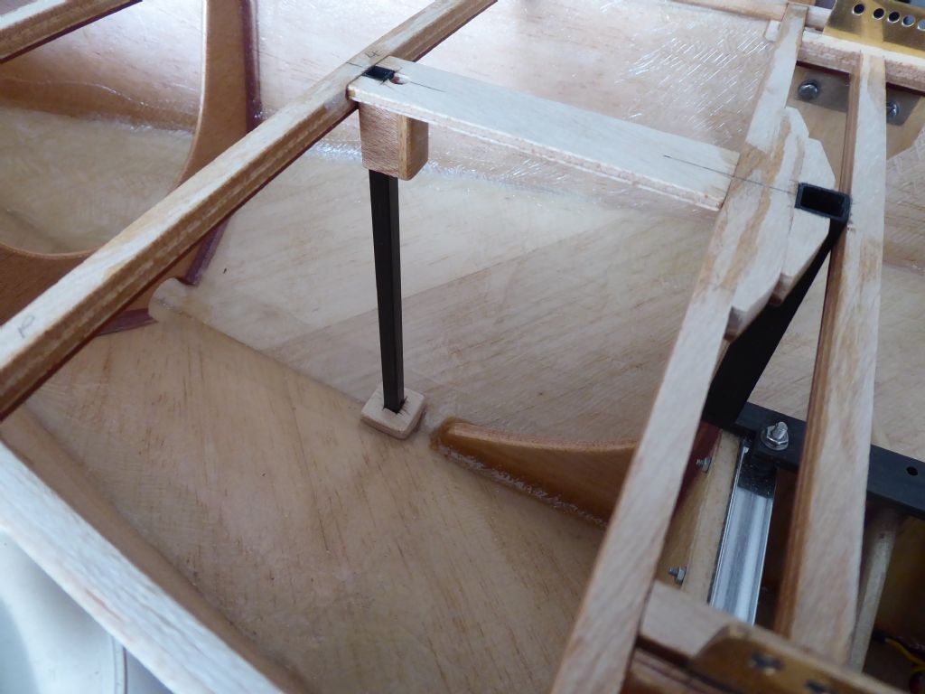
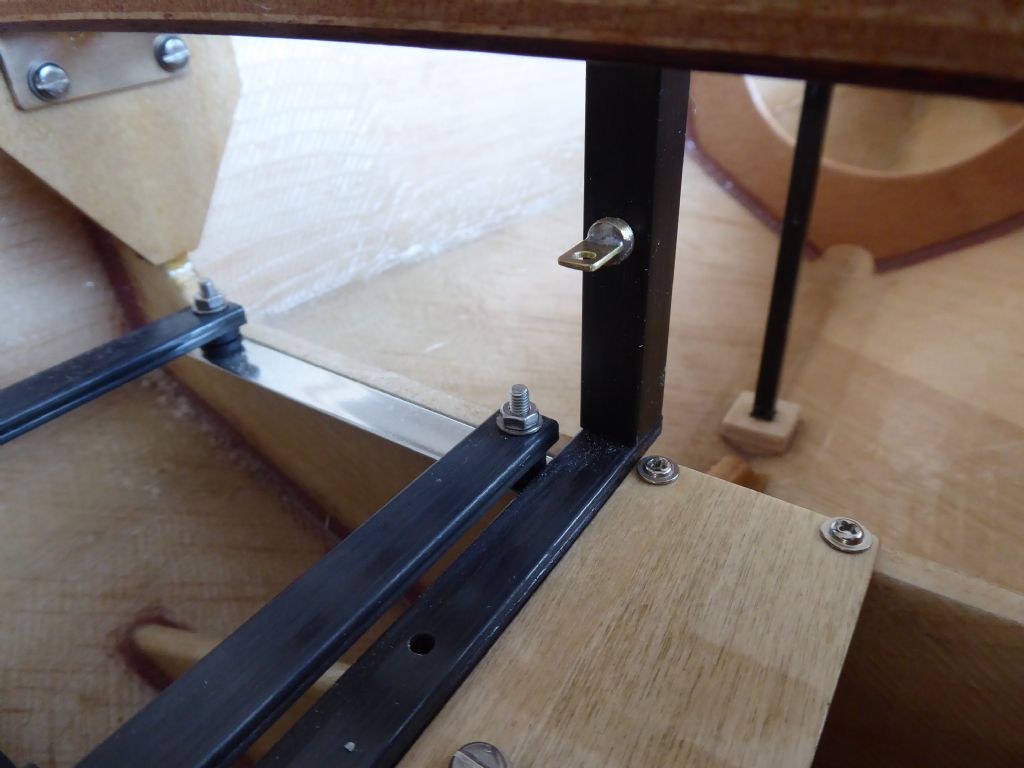
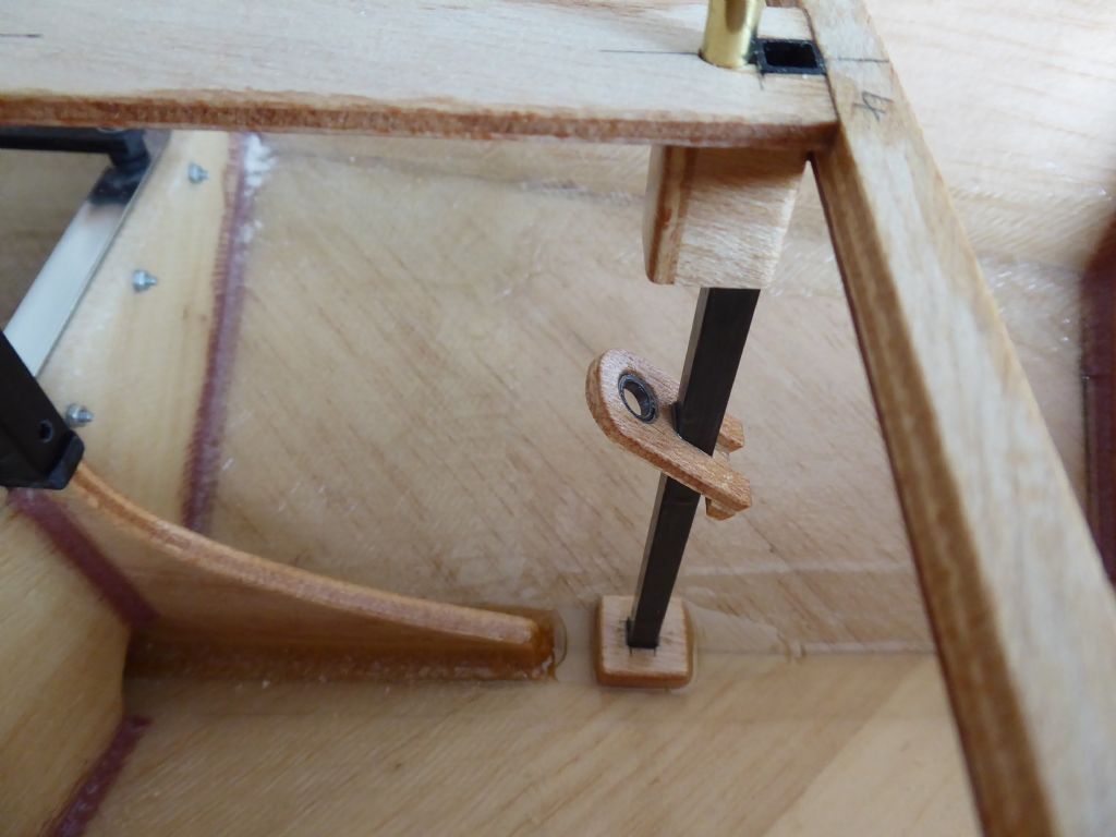
This is the post supporting the jib sheet. It locates in a block to spread the load a little and has a drain hole a fraction above the block just in case any water finds its way into the hollow carbon square. The block creates a little water trap so it will be filled with epoxy left over from a mix to make sure that any bilge water can flow aft to where eventually, there will be a bung.
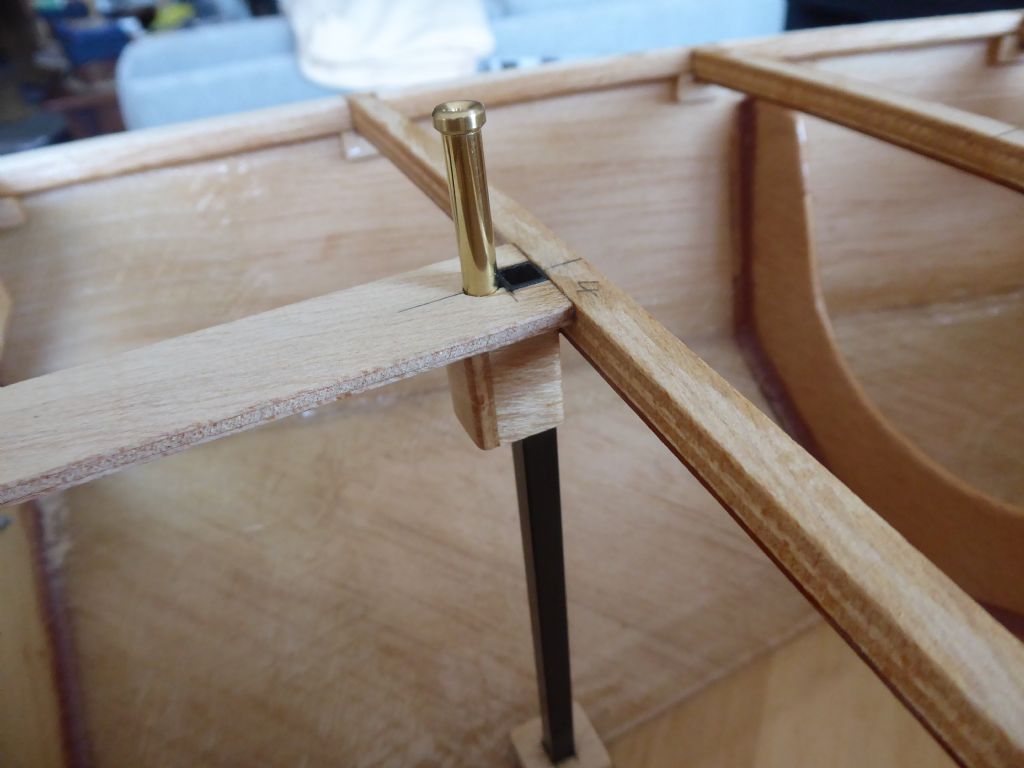
Here we are looking at the top detail of the main sheet post, this time with the brass tube in place. The top cap is flared internally to be kinder on the sheet and to keep the friction down as much as possible. It is slightly larger diameter than the tube to form a definite lip. If any water hits the tube and shoots up it will get thrown away from the tube helping to keep the water out. A bit like a breakwater, it may not be 100% effective but should do a useful job.
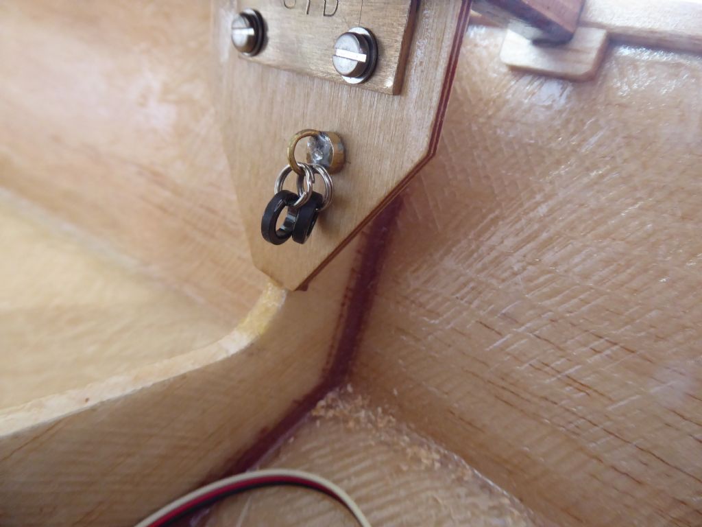
These are the leads from the servo arm to the sheet positions. I made a simple eyebolt by soldering some brass wire into a slot headed bolt. The black ceramic rings were from a fishing tackle shop (useful for model yacht stuff) and are line guides for rods sold as spares. They are attached to the eyebolt with stainless steel split rings again from the same shop.
A slightly different home made eyebolt on the mast compression post. This will take the fixed ends of the sheets and will take a small spring clip again courtesy of our fishing friends.
I did a test run with some polyester cord and felt that the friction was still a bit higher than I would like. The servo would cope (in fact it is so strong I am worried it could punch a hole in the side if it went over travel) I am sure but at the expense of shortened battery life.
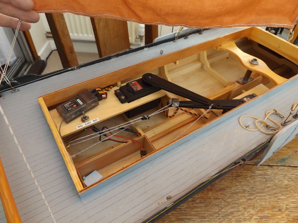
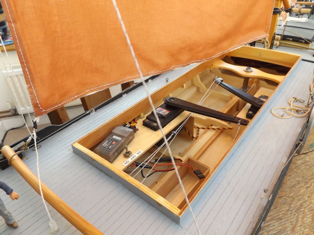
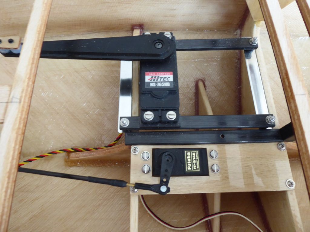
I had some spare ceramic rings so I glued them into these plates to provide a better lead up into the brass tubes. There was a definite improvement and when I rig the real sheets in Spectra which is quite slippery, I think it will work well enough. We shall see.Here we have the main gubbins and the sail servo arm sweeps over the rudder servo. The servo plate is screwed to the fibre reinforced webs using standard servo screws. If they rust too quickly I will have to find something else. Small pilot holes were drilled into the balsa care and then the screws wound in and then taken out. The holes were then dosed with some thin cyano to harden the balsa and the pilot drill used again. This makes a good secure fitting into balsa and clearly the rudder servo takes a fraction of the load of the sail servo which is much more heavily engineered.
There a few places where the sheets could snag and for sure getting tangled up in the rudder servo could prove interesting. Taking Ray's good advice I will fit a clear plastic panel over the rudder servo and other snagging points.
Tim R
15 February 2019 at 18:09 #81095 Ray Wood 3Participant@raywood3
Hi Tim,
How is the superstructure going to look ? Will she have a cabin & cockpit ? You look like you have the mechanical department well sorted 😁
Lovely blue sky day here.
Regards Ray
15 February 2019 at 21:22 #81099Tim Rowe
Participant@timrowe83142Hi Ray
No cabin and no cockpit like the original model. I am not a fan of either on working model yachts and they just add complication and weight. The highest things on the deck will be the sheet posts followed by the screw top plastic jar that I have finally decided to use after much chewing of the fat.
If this was a display yacht, then different.
I have decided on a patch over the rudder stock, a semi-permanent hatch over the gubbins and a screw top jar for quick access. At the moment I am undecided whether to have a switch and two charging points and have two batteries tucked away as low as possible or have the battery in the pot so I can take it off for charging and do away with the switch. I am not a fan of switches either and may just use a link instead. What do you think?
Tim R
-
AuthorPosts
- Please log in to reply to this topic. Registering is free and easy using the links on the menu at the top of this page.
Code of conduct | Forum Help/FAQs
Latest Replies
Home › Forums › Sailing Models › Topics
-
- Topic
- Voices
- Posts
- Last Post
-
-
Fairey Huntsman 31
1
2
…
5
6
Started by:
 Chris Fellows
in: Build Blogs
- 14
- 139
-
3 hours, 35 minutes ago
 Chris Fellows
-
Fairey Faun
1
2
3
Started by:
 Chris Fellows
in: Build Blogs
- 7
- 58
-
3 hours, 57 minutes ago
 Chris Fellows
-
Vic Smeed’s Silver Mist
1
2
…
32
33
Started by:
Bob Abell 2 in: Scratch build
- 4
- 822
-
4 hours, 35 minutes ago
 Tony Hadley
-
Fairey Huntsman 28
1
2
…
7
8
Started by:
 Chris Fellows
in: Build Blogs
- 1
- 195
-
6 hours, 5 minutes ago
 Chris Fellows
-
Eezebilt RAF Fire Boat
Started by:
Tim Cooper in: Build Blogs
- 2
- 3
-
6 hours, 40 minutes ago
 Dave Reed
-
Feathered Friends
Started by:
 Chris Fellows
in: Soapbox
- 3
- 7
-
9 hours, 47 minutes ago
 Chris Fellows
-
4D Modelshop
Started by:
Keith Long in: Scratch build
- 6
- 7
-
10 hours, 15 minutes ago
 Chris Fellows
-
John Cobb’s Crusader
1
2
…
7
8
Started by:
 Paul T
in: Scratch build
- 1
- 192
-
1 day, 6 hours ago
 John W E
-
Complex Automata
Started by:
 Colin Bishop
in: Soapbox
- 1
- 1
-
2 days, 8 hours ago
 Colin Bishop
-
RAF Fireboat ID
Started by:
 Dave Reed
in: Collectors’ corner
- 8
- 24
-
3 days, 10 hours ago
Tim Cooper
-
TID steam tug 42″ – PN Thomas drawing enlarged
1
2
Started by:
 Ray Wood 3
in: Scratch build
- 8
- 33
-
4 days, 3 hours ago
 Richard Simpson
-
Lady of Skye (puffer)
1
2
Started by:
 mick east
in: Build Blogs
- 9
- 43
-
4 days, 13 hours ago
 Richard Simpson
-
Building a hull.
Started by:
 mick east
in: Scratch build
- 7
- 10
-
6 days, 12 hours ago
 Ray Wood 3
-
Todays Boating
1
2
…
210
211
Started by:
 ashley needham
in: All things floating
- 84
- 5,252
-
1 week ago
 Colin Bishop
-
Sea Rover Restoration
Started by:
harry smith 1 in: Collectors’ corner
- 4
- 10
-
1 week ago
 Richard Simpson
-
WORKSHOP LIGHTING
Started by:
 John W E
in: All things floating
- 9
- 18
-
1 week, 1 day ago
 Colin Bishop
-
Mayhem Website Down
Started by:
 Colin Bishop
in: All things floating
- 4
- 10
-
1 week, 4 days ago
 Colin Bishop
-
MAGGIE M trawler
Started by:
 sammyk
in: Buy/Sell or Trade
- 2
- 3
-
1 week, 4 days ago
 sammyk
-
meter
Started by:
 Alasdair Allan
in: All things floating
- 5
- 16
-
1 week, 6 days ago
 Chris Fellows
-
River Queen 2”- 1’.
Started by:
Richard B in: Steam powered models
- 5
- 7
-
1 week, 6 days ago
Richard B
-
Deluxe Superphatic Glue.
Started by:
 Colin Bishop
in: All things floating
- 4
- 12
-
2 weeks ago
 Chris Fellows
-
How to add photos to your posts
Started by:
 Colin Bishop
in: Adding Images to Forum Posts
- 3
- 16
-
2 weeks ago
Len Morris 2
-
Cataract
Started by:
Bob Wilson in: Soapbox
- 2
- 4
-
2 weeks, 1 day ago
 Colin Bishop
-
The mighty tug Wattle
1
2
3
Started by:
 mick east
in: Build Blogs
- 10
- 61
-
2 weeks, 1 day ago
 Richard Simpson
-
Clyde Puffer Glenaray
1
2
3
Started by:
 Alasdair Allan
in: Build Blogs
- 6
- 57
-
2 weeks, 4 days ago
 Alasdair Allan
-
Fairey Huntsman 31
1
2
…
5
6
-


