The world's leading magazine for all model boating interests
Eilean Mor
Eilean Mor
Home › Forums › Building Kits › Eilean Mor
- This topic is empty.
-
AuthorPosts
-
15 December 2014 at 16:05 #54356
Banjoman
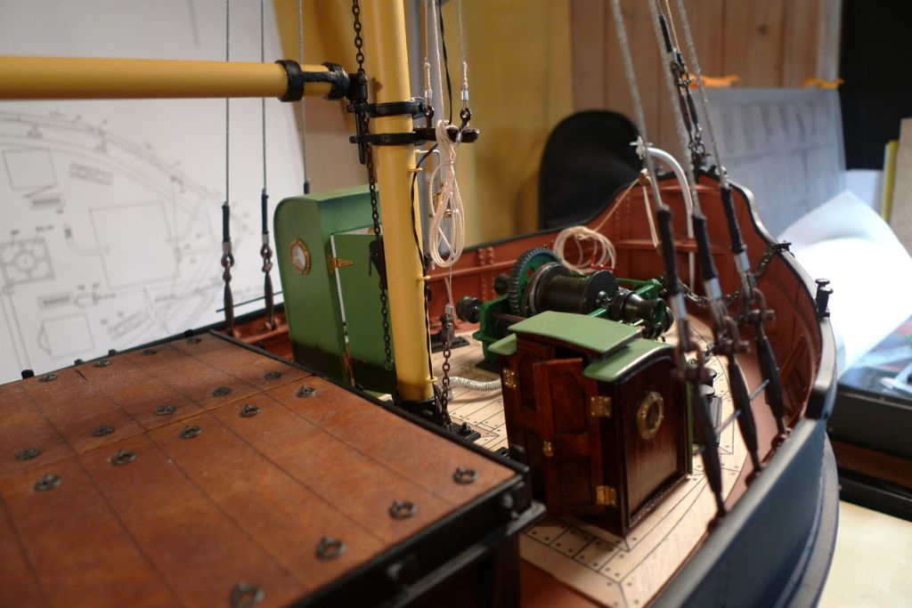
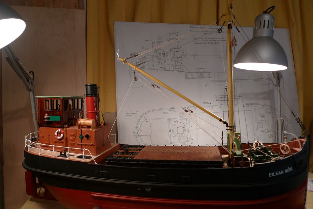
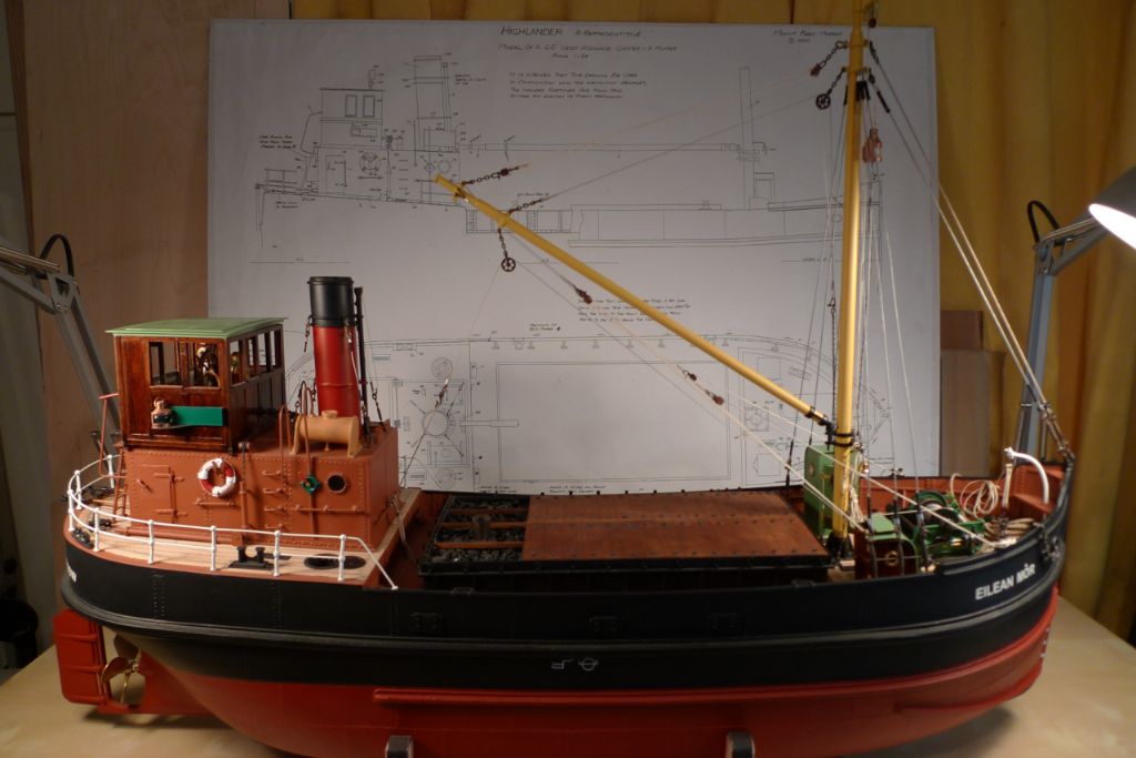
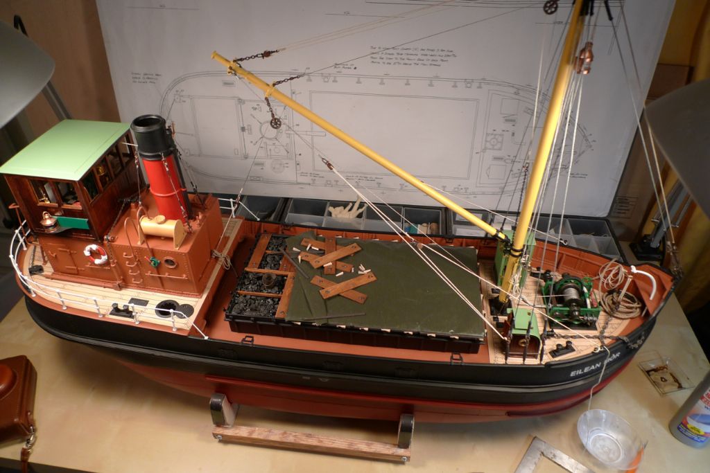
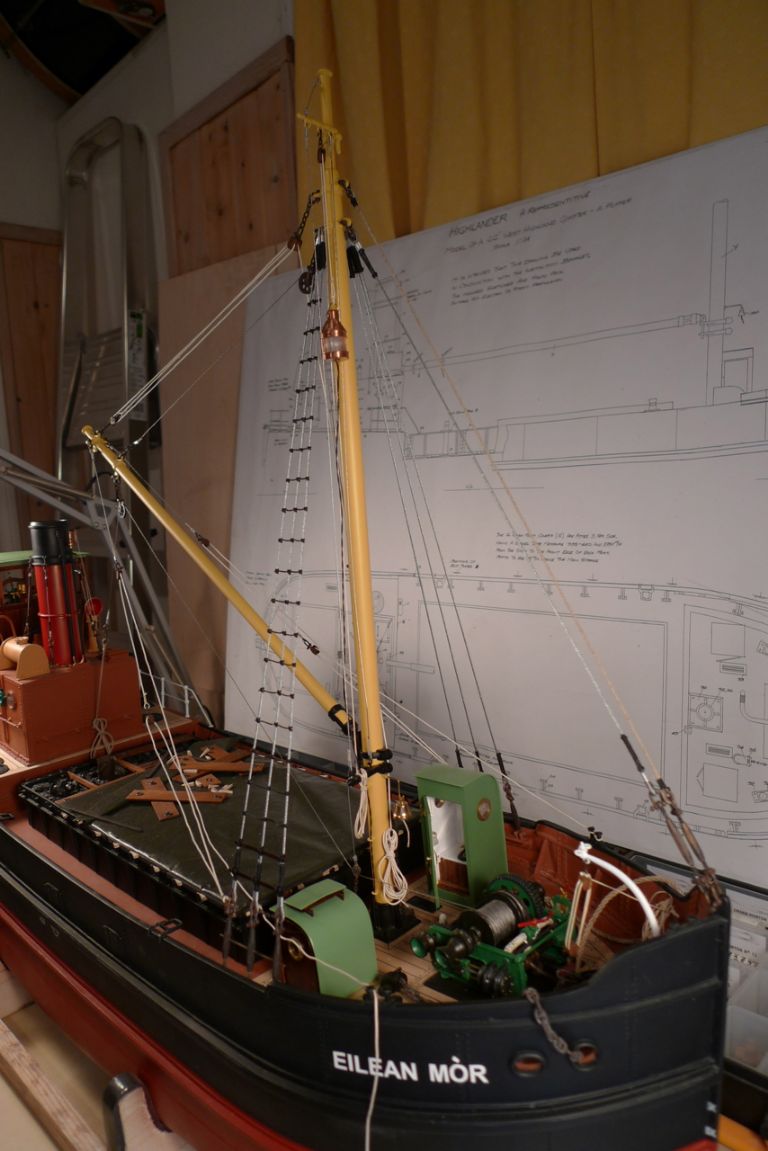
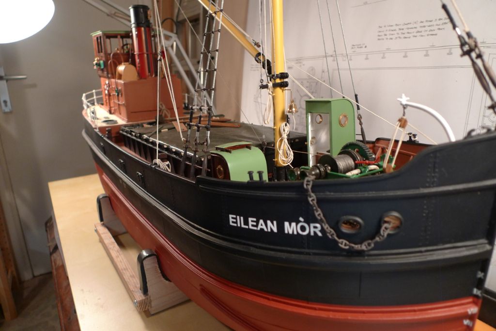
Participant@banjomanFurther to the rigging, the temporary whip lead block suspension was replaced by some 0.3 mm wire attached to the lower mast outrigger.
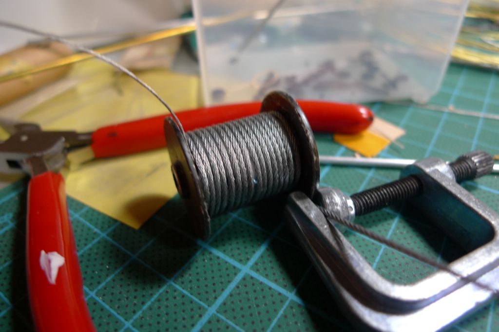
I then made a first attempt at installing a steel wire preventor. However, the wire (from RB Model) turned out to be too tightly laid, and thus not flexible enough to produce a soft curve over the mast top gin block. I had some softer wire of the same dimension from Eskader on hand, but not long enough, so an order went off to Stockholm …
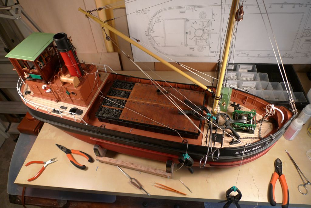
… while in the meanwhile I got on with rigging the boom guy ropes. I've already discussed the research that went into finding out how these ought to be rigged — see **LINK**. Suffice it to say here …
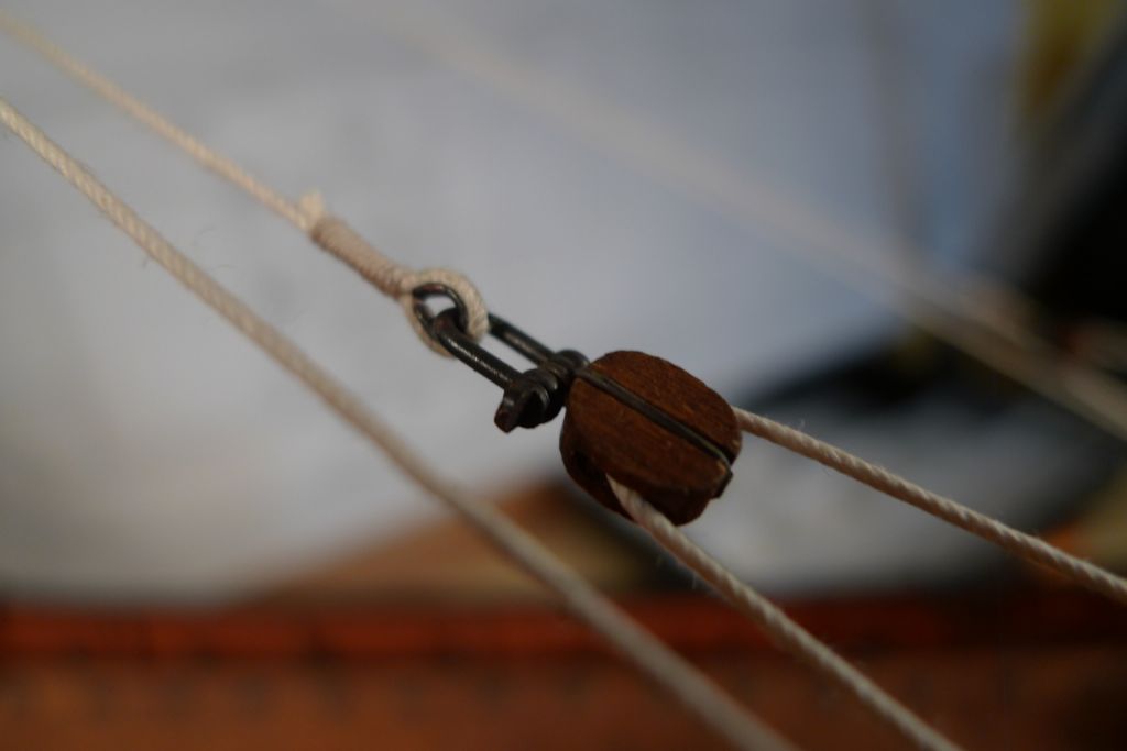
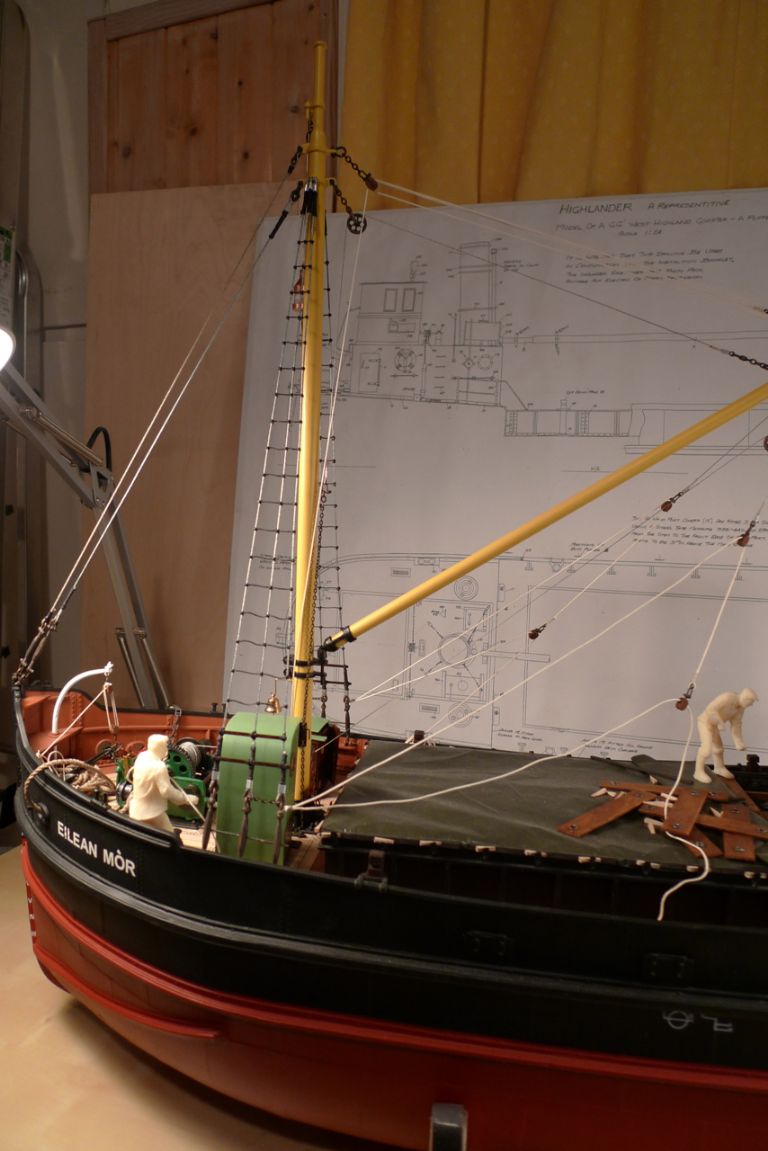
… that I eventually settled on single Spanish burtons, with 0.5 mm wire pendants and blocks shackled to the boom spider band …
… with a second block shackled to one end of the guy rope, which was then rove through the pendant block …
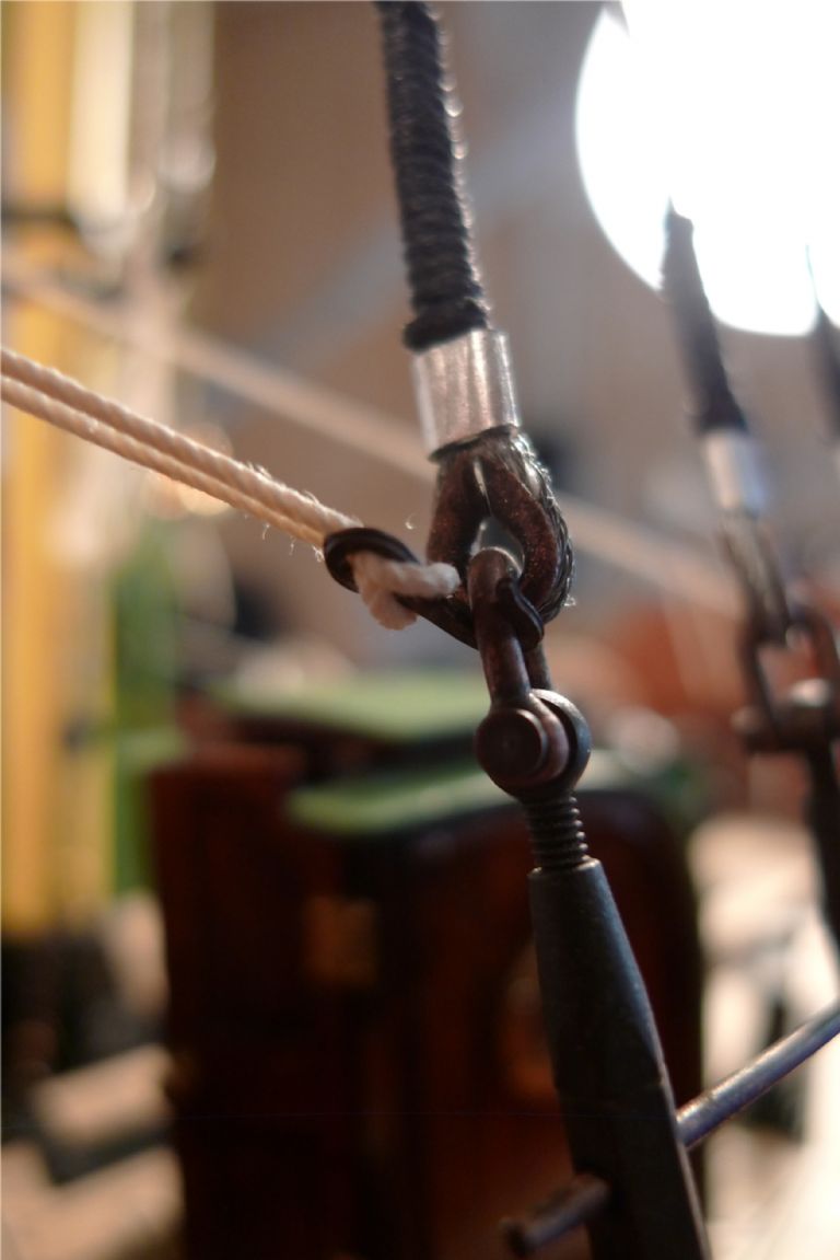
… taken in a bight thrugh the eye and around the shank of a rigging hook (here hooked onto the mast stays) …
… and (temporarily) belayed on the bow bulwark bollards.
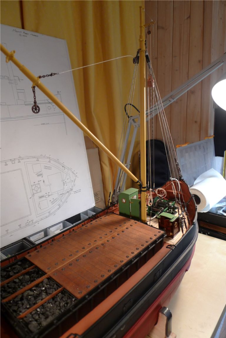
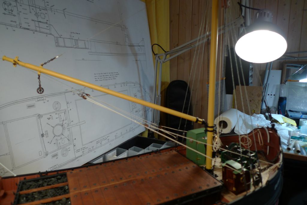
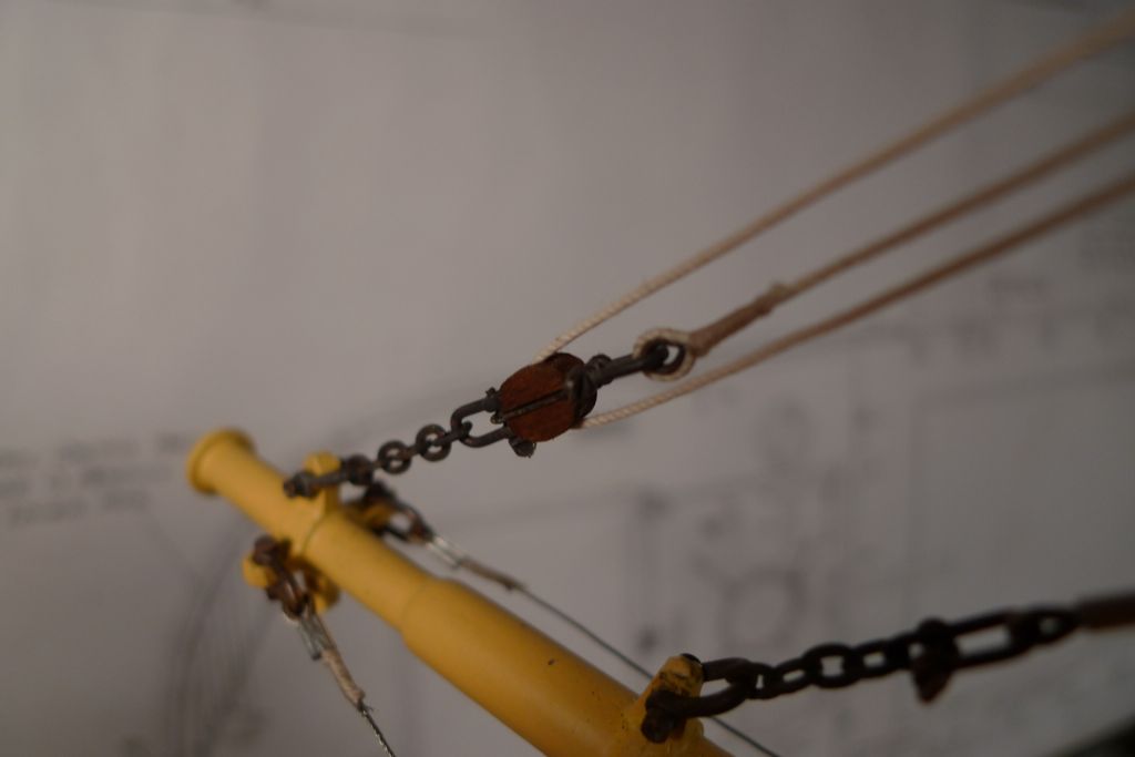
I also set up the boom topping lift …
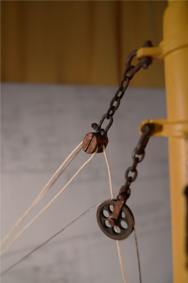
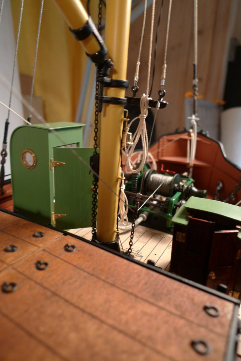
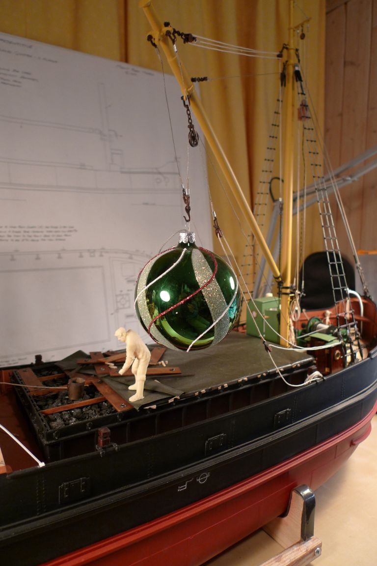
… as a luff tackle. Oh, and by the time I got to this point, I'd also received the ordered 0.5 mm steel wire from Eskader, and as the below photo shows, this one was laid loosely enough that the wire would form a nicely shaped curve over the gin block even undetr the rather negligable weight of just the boom.
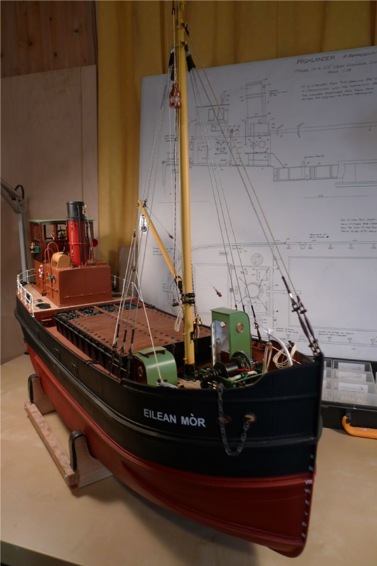
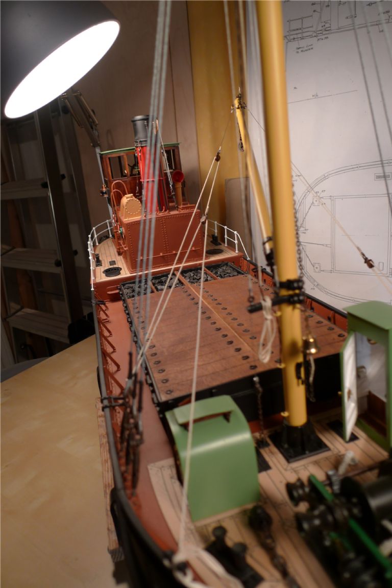
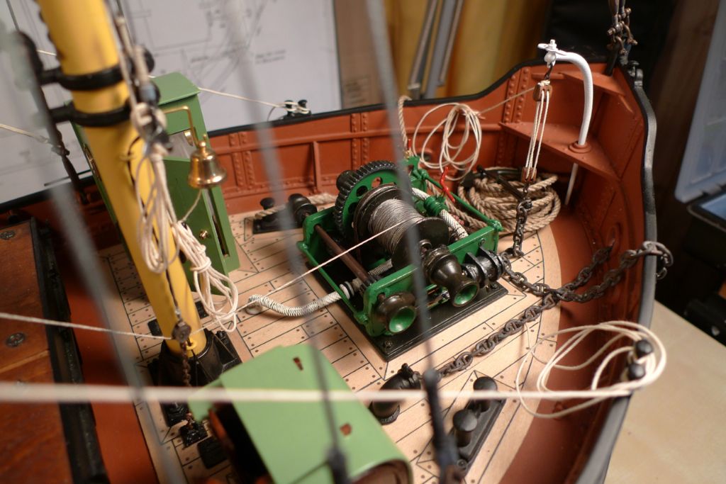
All these running parts of the rigging …
… are fully working …
… although the weight of the boom and other bits and bobs are not really suffiicient to overcome the friction of the blocks. But then, on the other hand, I'm not planning to actually work the boom either, so it is not too much of an issue …

To be continued …
/Mattias
Edited By Banjoman on 15/12/2014 16:05:48
Edited By Banjoman on 15/12/2014 16:06:14
Edited By Banjoman on 15/12/2014 16:06:45
15 December 2014 at 20:44 #54367Gareth Jones
Participant@garethjones79649Hi Mattias,
You are still keeping up a very high standard, lovely attention to detail and everything so neat and crisp.
Where did you get your rigging shackles from? The smallest ones I found were Modelling Timber's 7 mm x 4 mm but yours look smaller than that. I ended up making all the ones on Shemarah from brass wire and that was 1:25 scale, near enough the same as your Puffer. The ones you have used look much better than my home made attempts.
Gareth
15 December 2014 at 21:34 #54368Banjoman
Participant@banjomanHello Gareth,
And thank you very much for your kind words!
Those shackles are actually the same that are sold by, amongst others, Modelling Timbers, and originally made by the Polish aftermarket parts company RB Model (**LINK**).
I have used three different shackles on Eilean Mòr: the smallest, i.e. the 7×4 mm D shackles, with a M1 threaded bolt, the 8.6×5.6 mm D shackles with a M1.4 nut and bolt (both listed here: **LINK**) and the 8.6×6 mm bow shackles with wired pin (**LINK**), and (depending on what other things I've wanted to order at the same time) bought them from either Cornwall Model Boats, The Model Dockyard or direct from RB Model.
I have also to some extent mixed and matched pins, in particular replacing some of the wired pins for the bow shackles with nuts and bolts out of the RB Model assortment. And yes, I know that in real life a shackle pin must never be replaced by an ordinary bolt, as the latter is likely to be sufficiently weaker that the shackle can no longer be trusted with the load it is supposed to be able to take, but I don't think that that is going to be too much of an issue on a model …

As you will surely have noted, I have also chemically blackened them with A-West Blacken-it, which I think gives them a decent look and a nice patina.
Anyway, from what I've understood these shackles were originally developed for the 1:35 plastic kit armour model range (which I think make up the largest single part of the RB Model catalogue), but although they might be slightly out-of-scale on a 1:24 ship (where for instance 7×4 mm would equal 168×96 mm in real life) it is not too horribly so, and at least in my eyes they don't look too clumsy our out of place once they're in the rigging.
I really like using them, because they add some nice and fairly realistic detail, but also very much because they attach things quite solidly, but keep them fully detachable at the same time which is quite handy in a rig.
/Mattias
Edited By Banjoman on 15/12/2014 21:35:24
16 December 2014 at 21:27 #54403IAN_I
Participant@ian_iHi Mattias…
The build is coming along and looks great with all the detailed work.
Regards,
Ian
17 December 2014 at 08:50 #54413Banjoman
Participant@banjomanThank you very much indeed, Ian!
As I'm sure you've already realised, I'm as yet only catching up in this thread — the build actually began in July last year, so I am certainly not building at the speed at which I'm posting …

Anyway, the next job to tackle was rigging the whip. I had been thinking back and forth about how to stow the hook, as it would not be possible to just leave it dangling; in part because this would be quite unrealistic (a real-life cargo hook is, I think, heavy enough to brain someone or otherwise do serious damage if left to dangle uncheched), but also because the etched brass hook that I intended to use just simply wouldn't be heavy enough to keep the whip nicely stretched and tight.
I'm sure that in real life, all manners of stowing were employed, including un-schackling the hook and just making the end of the whip fast somewhere, for example by lashing it to the boom. However, I wanted something that would both look nice and be practical in the sense that it'd allow me to move the boom up and down and/or sideways using the topping lift and guys, while still keeping the whip under sufficient tension that it'd lay straight and look nice. Any solution would also have to take into account that the engine room and cargo hatch have to be able to come off to give access to the technical installations.
Anyway, as a point of departure, I decided on not resting the boom in its cradle but rather elevating it a bit, like one often sees in period photos of Puffers in passage, and to secure the whip to the handrail on the front of the engine room casing. I first tested an elastic attachment (here just a rubberband, to have been replaced by some black elastic thread from the haberdasher's), but in the end decided against that (see below).
I then began attaching the whip steel wire to the winch drum. I decided to use 0.5 mm wire for this, just as for the preventor, as this would represent a 12 mm wire to scale, and a 12 mm steel wire has a safe load of just under one and a half tonnes, which I think is realistic for a Puffer, where usually bulk cargoes like coal was unloaded by so called buckets, the content of which when filled up was supposed to be one (imperial) ton.
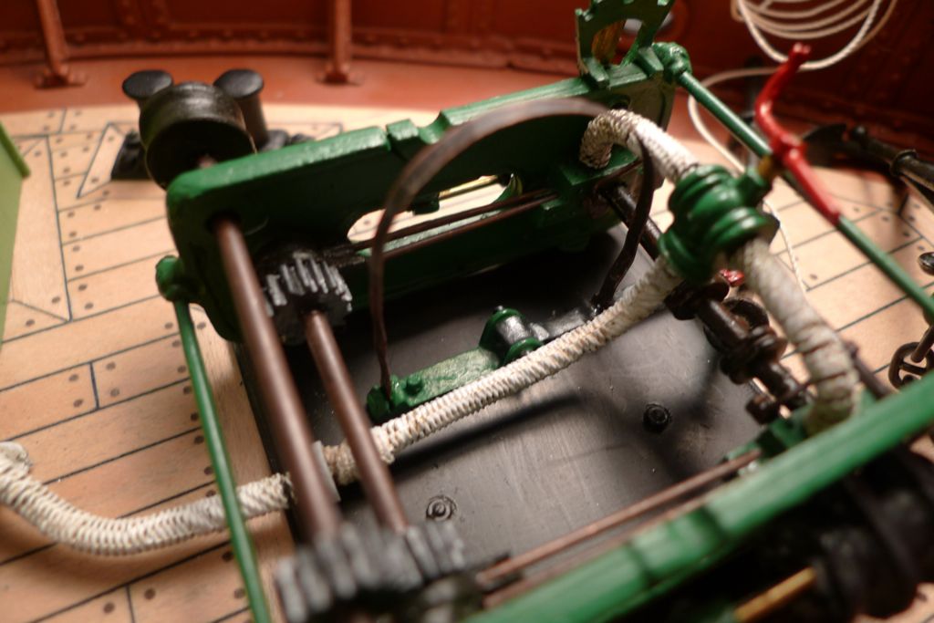
However, I first epoxied a single layer of 1 mm wire to the drum, to create a wire-coloured bottom layer and fill out the load on the drum with a shorter length of wire than would have been required had I used 0.5 mm all the way. The standing end of the 0.5 mm wire was simultaneously secured under a few of the 1.0 mm wire loops.
This also had a serendipitous side-effect to which I'll come back below.
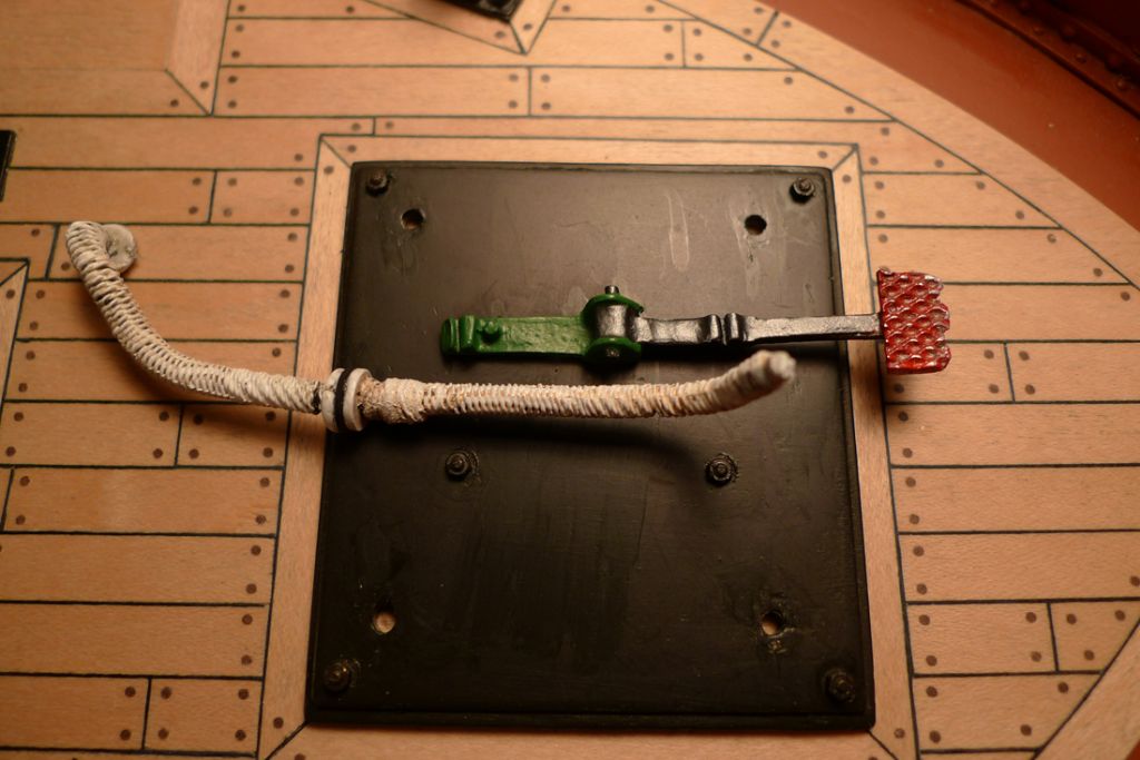
The winch brake band was glued in place on the brake pedal
The thimble and shackle at the running end of the whip could not be secured off the model, as the whip first had to be rove through the lead block and neither of these contraptions would fir through there. It also had to be rove through the gin block, but while it is not snatch block proper, because it is held together with nuts and bolts (as described in a previous posting) it can if necessary be opened up and closed again.
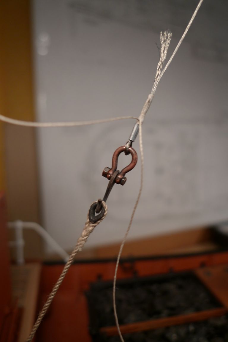
Anyway, the whip was rove through, and the hook, shackle and thimble assembly secured to the handrail using a rope-and-thimble set-up (kept tensioned by a weight over the bulwark) while the wire was temporarily stopped at the lead block with some clamps.
This kept the tension sufficiently up for me to be able to crimp and serve the end of the whip wire in the usual manner.
On the securing rope (the remaining length of the 1.1 mm rope I'd also used for the upper forestay) a thimble was spliced into one end …
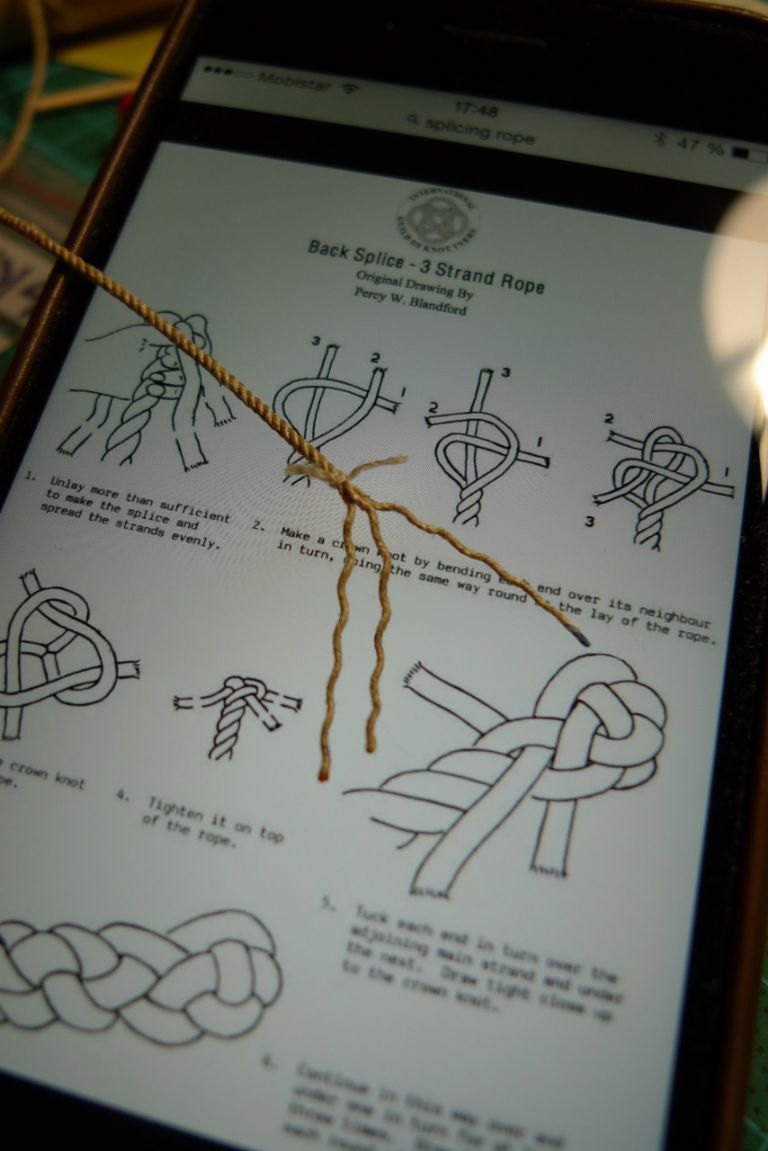
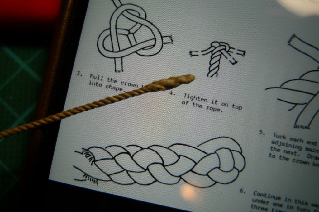
… and a back splice attempted …
… at the other end. It doesn't perhaps look quite quite, but at least it is a real back splice.
To be continued …
/Mattias
17 December 2014 at 08:51 #54414Banjoman
Participant@banjomanI mentioned serendipity in the previous post, and here's the explanation:
I'd put a fair amount of thinking into whether or not the winch drum might have been made securable, i.e. not glued set but kept rotating with some means of fixing it in a desired position, but, alack and alas!, I'd been unable to come up with anything that would both work and remain invisible from the outside.
However, when I served the drum with the initial layer of 1.0 mm wire, I first drilled through the drum next to one of the rims, and inserted about 15 mm or so of the wire end into the hole, just in order to facilitate winding it on and fixing it in place while the epoxy went off.
This inevitably meant that 15 mm of wire pointed down straight through the centre of the drum, i.e. straight through the path of the axle, and when pushed aside to let the axle pass sprang back against the axle under its own tension. I had thus by pure accident created a spring loaded brake against the axle, so that by fixing the axle with glue against the winch frame, the drum could be left rotating yet with friction enough from the brake to stay put in any desired position.
I could therefore also leave the last 15 cm or so of the 0.5 mm whip wire free to wind and unwind on the drum. Apart from making the whole set-up adjustable, this is a nice security feature, because it means that if I strike the whip or boom by accident (and I've already managed to do that on several occasions) nothing will break or come off — the wire will just unwind from the drum and the whip slacken! Pure serendipity

It is also very handy when managing the boat for sailing. By simply slackening off the whip at the drum …
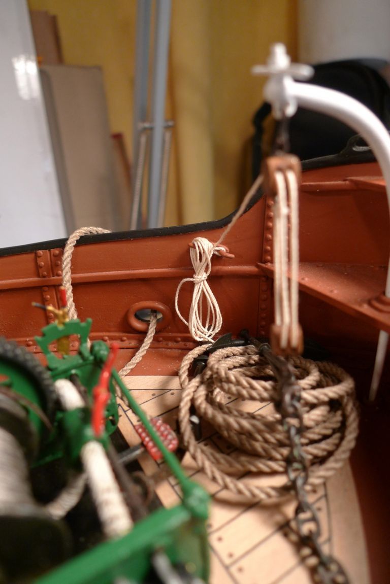
… the hook can be unshipped from its securing rope, thus freeing the engine room casing and also making it easier to reach in and lift off the cargo hatch if needed (to get at the main battery, the r/x and the on/off switch for the mast top light). When ready to go, the rope is just rehooked and the drum wound back again to tension the whip. Furthermore, this set-up holds the boom wuite steady and also nicely tensions the topping lift and preventor to give them the desired look of being under weight from the boom.
To be continued …
/Mattias
Edited By Banjoman on 17/12/2014 08:52:29
Edited By Banjoman on 17/12/2014 08:54:38
18 December 2014 at 09:06 #54423Banjoman
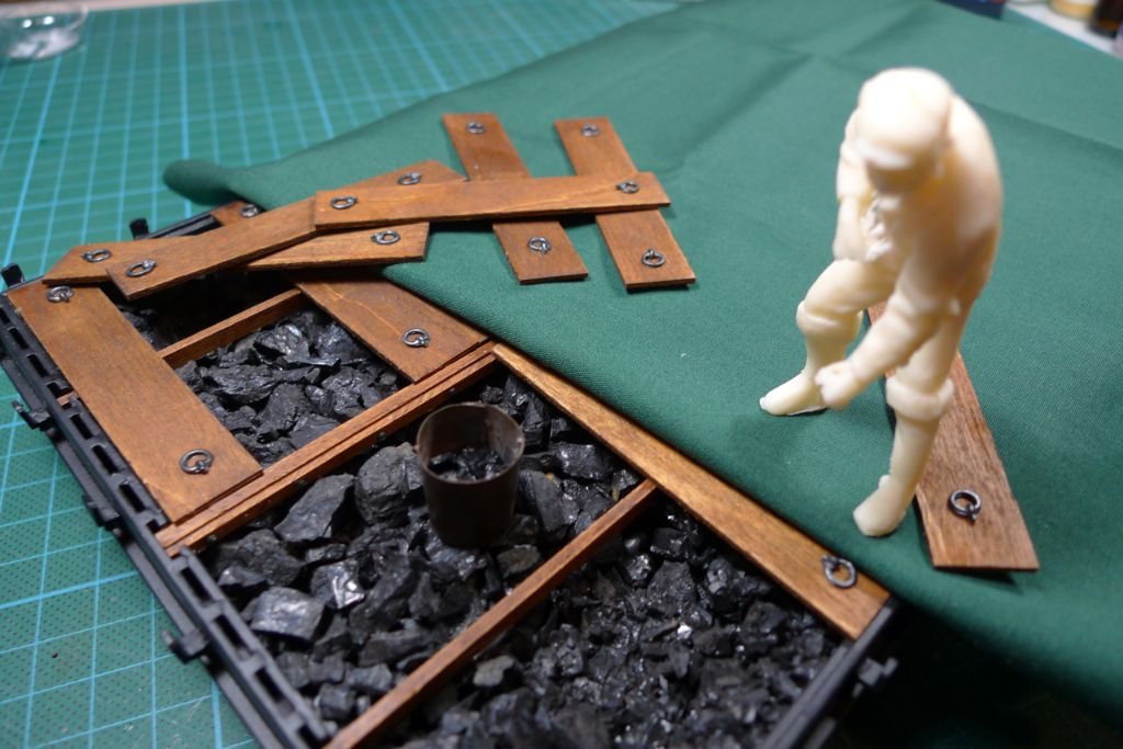
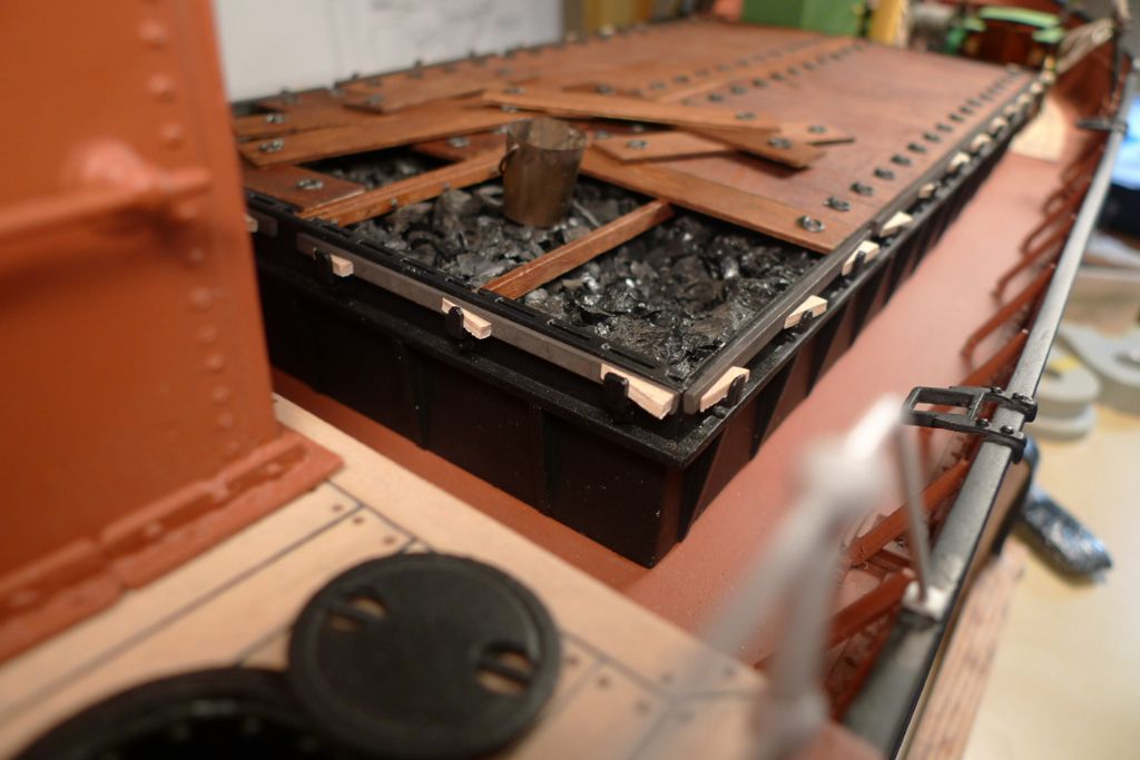
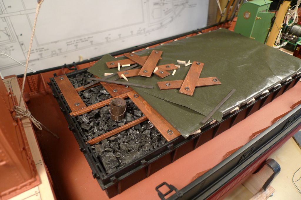
Participant@banjomanI now decided to tackle the final jobs on the main hatch, namely the loose cover boards, the tarpaulin and the battens and wedges.
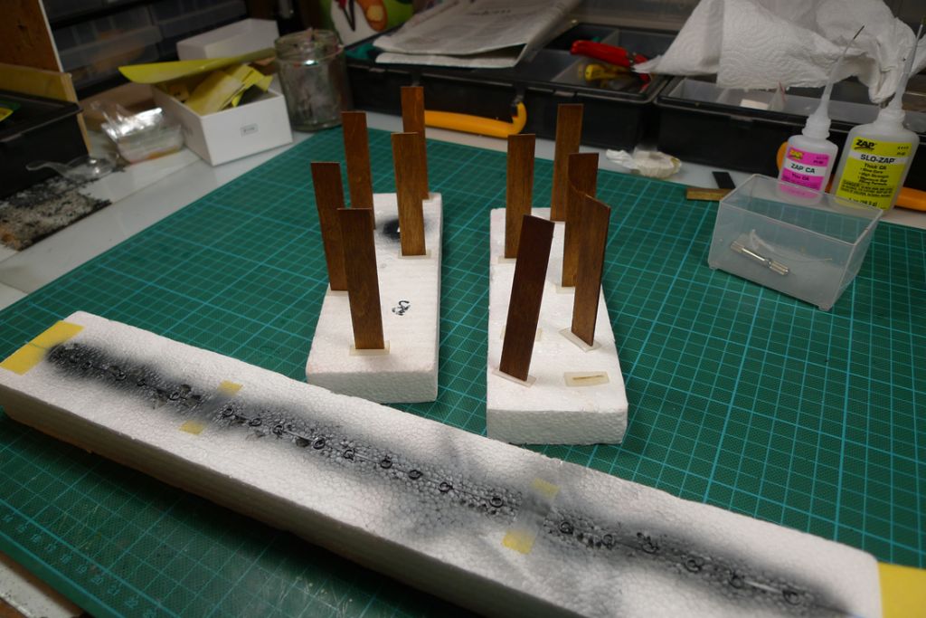
The cover boards had been cut to size much earlier, concurrently with building the hatch box, but I now finished them off with a couple of coats of satin varnish and also airbrush painted and glued on their ringbolts.
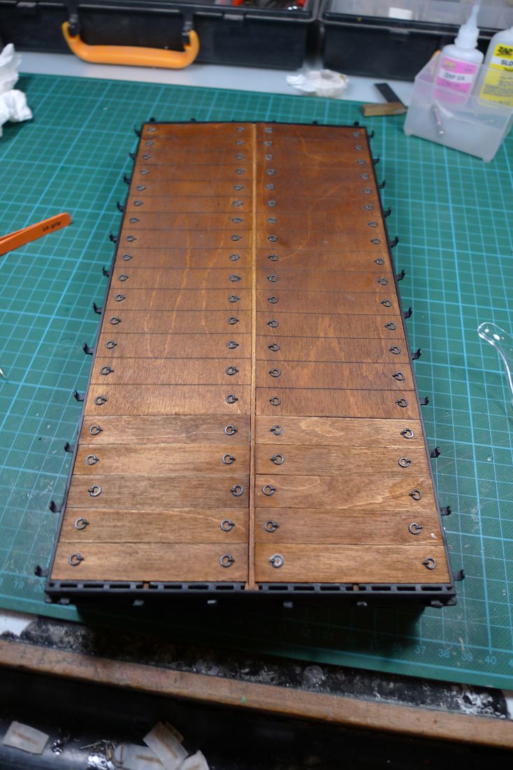
This gave me a complete set of coverboards for the hatch …
…although as previsouly mentioned, the idea was to leave the aft end open, as though a few battens had been removed, the tarp pulled back and some of the cover boards lifted out. The three loose boards shown still in place here have thus been glued down; the others remain loose for the time being (although I shall probably glue them into their helter-skelter positions at the very end of the build, to prevent them from getting lost or blown overboard when sailing).
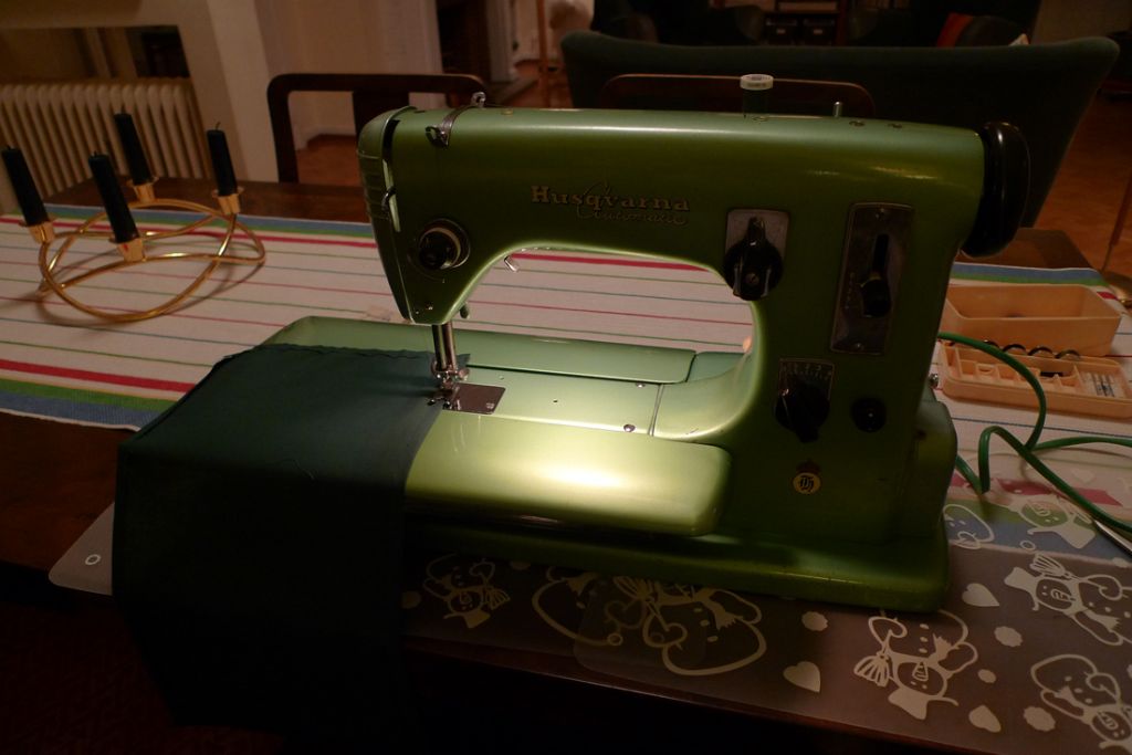
The kit came with a piece of green synthetic cloth from which to make up a tarpaulin. I was a bit worried, though, by the fact that this material, which is woven, did not have very stable edges — threads kept coming loose all the time. For a completely battened down tarp, this would not have mattered too much, but for part of the tarp to be shown folded back, the underside would have to be able to be shown, too …
…. and I thus tried cutting the material down to size and hemming the edges. This, however, made the edges much too thick to fit under the battens, and really did not look good at all. I therefore discarded this material all together, and sent off for some other stuff, but more about that below.
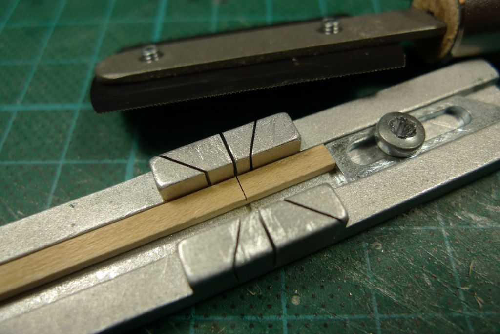
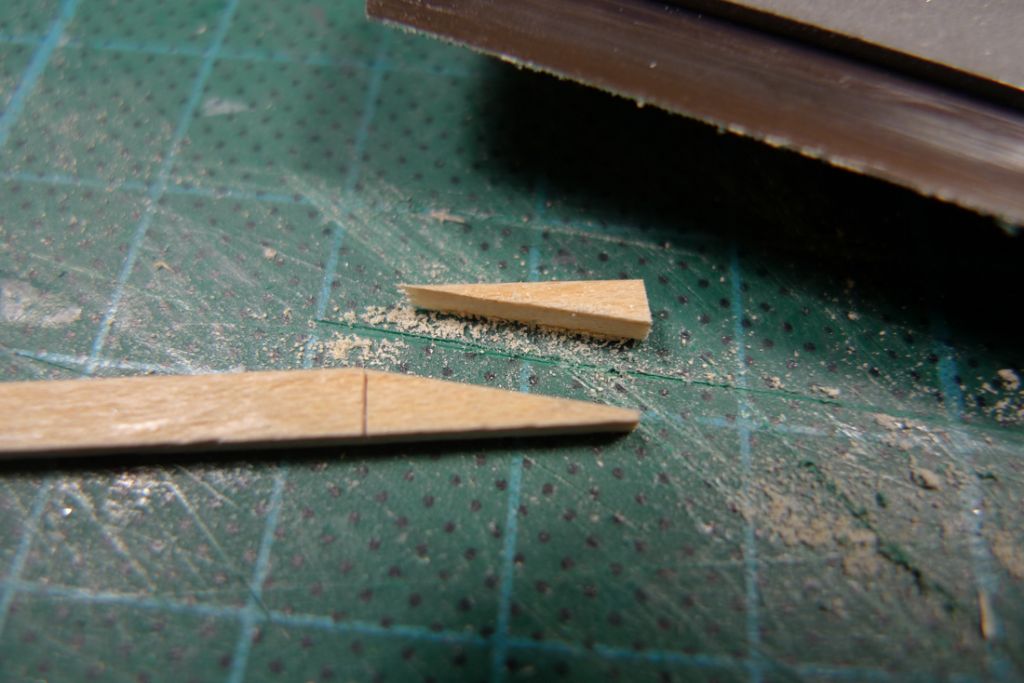
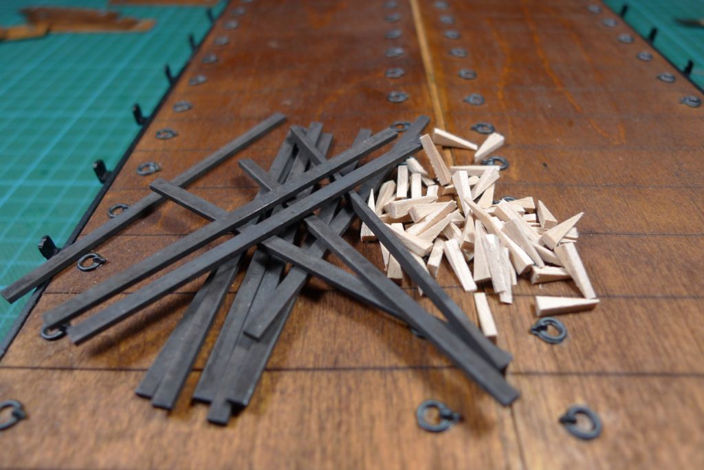
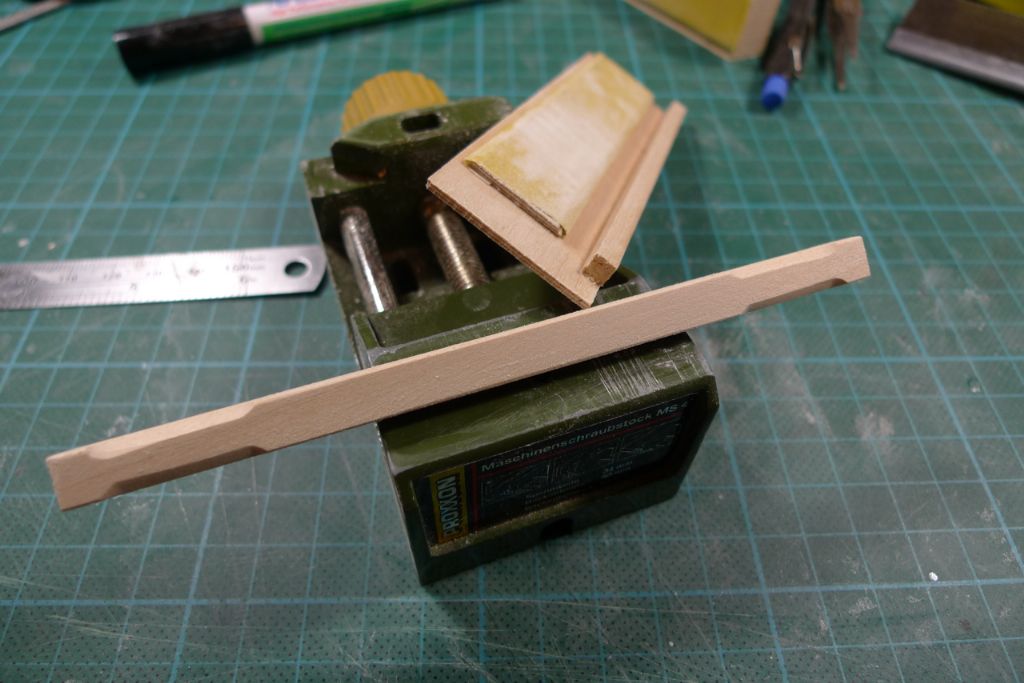
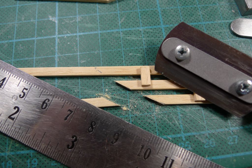
In the meantime, I began cutting to size the 36 wedges I would need. For this, I first made a shallow sqaure cut into a 1.5×4 mm maple strip, using the micro mitre box to set the distance …
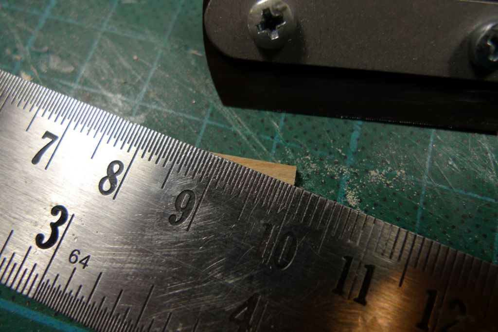
… and then, with a steel ruler as a guide sawed the strip through on the diagonal …
… to produce one wedge. By then sawing through the initial square cut, a second, identical wedge was produced, and the strip was squared off, ready for the next two wedges to be produced.
To be continued …
/Mattias
Edited By Banjoman on 18/12/2014 09:09:16
18 December 2014 at 09:06 #54424Banjoman
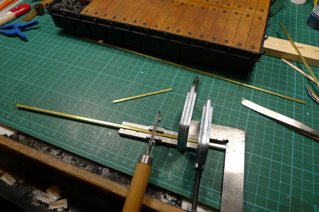
Participant@banjomanI also used the razor saw and micro mitre box to cut the 12 battens down from lengths of 1.5×3 mm brass strip, with an improvised extension to set the distance.
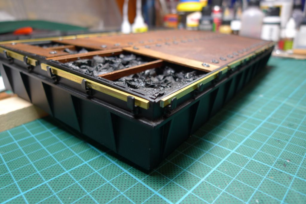
I then checked the fit of the battens on the hatch …
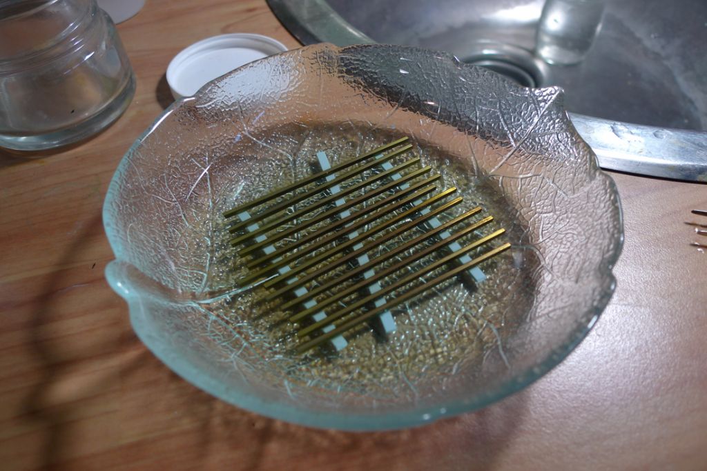
… before giving them an extended bath in some watered down Blacken-it.
This produced a set of battens that not only look pretty much like they might be made from iron, but also has a little bit of weight to them, and which cannot be intended by the wedges as would have been the case had they been made from wood strip.
I again checked the fit of battens and wedges …
… and the returned to the problem of the tarpaulin. While working on the wedges and battens, I'd sent off to Airtek for some dark green Litespan, and found that this was really a quite ideal material for making up a tarp!
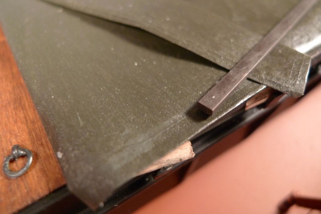
After carefully ironing wrinkles and folds out of the Litespan (with a not too hot iron, to keep it from shrinking too much), I cut out two rectangular pieces: one the exact size desired for the finished tarp, and the other some four mm larger on each side. These were glued together, back to back, with watered down PVA, and the edges of the larger piece folded in and glued down too. This gave the tarp pretty much the right thickness, and made both top and bottom sides look the same.
Wih a 0.5 mm "Rosie the Riveter" spur wheel I then traced twice around the edges, to make it look like they'd been hemmed.
I'm quite happy with the result: not only does it look pretty much like a tarp, it is also thin enough to fold over nicely, and to lay well and flat even under little weight.
Technically it actually is a tarp, too, because the Litespan is in fact completely waterproof!
If one were to be really, really picky, I suppose one could take issue with the fact that it does perhaps look a tad more like a modern-materíal tarp than the waterproofed canvas that I suspect would have been much more likely in 1951 (most modern tarp fabrics were invented by then, but probably not yet really commercialised).
Given all the other positive points, though, I'm willing to put my fingers in my ears and to go la-la-la on this particular issue …

To be continued …
/Mattias
Edited By Banjoman on 18/12/2014 09:11:48
19 December 2014 at 07:35 #54433Banjoman
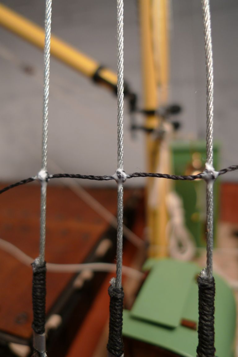
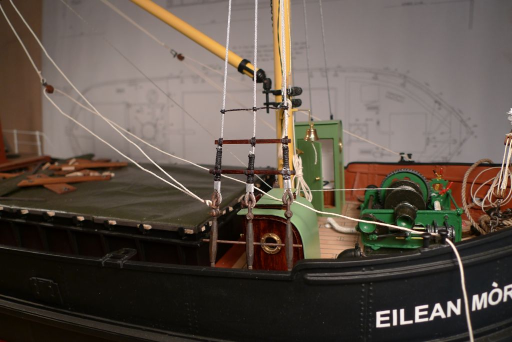
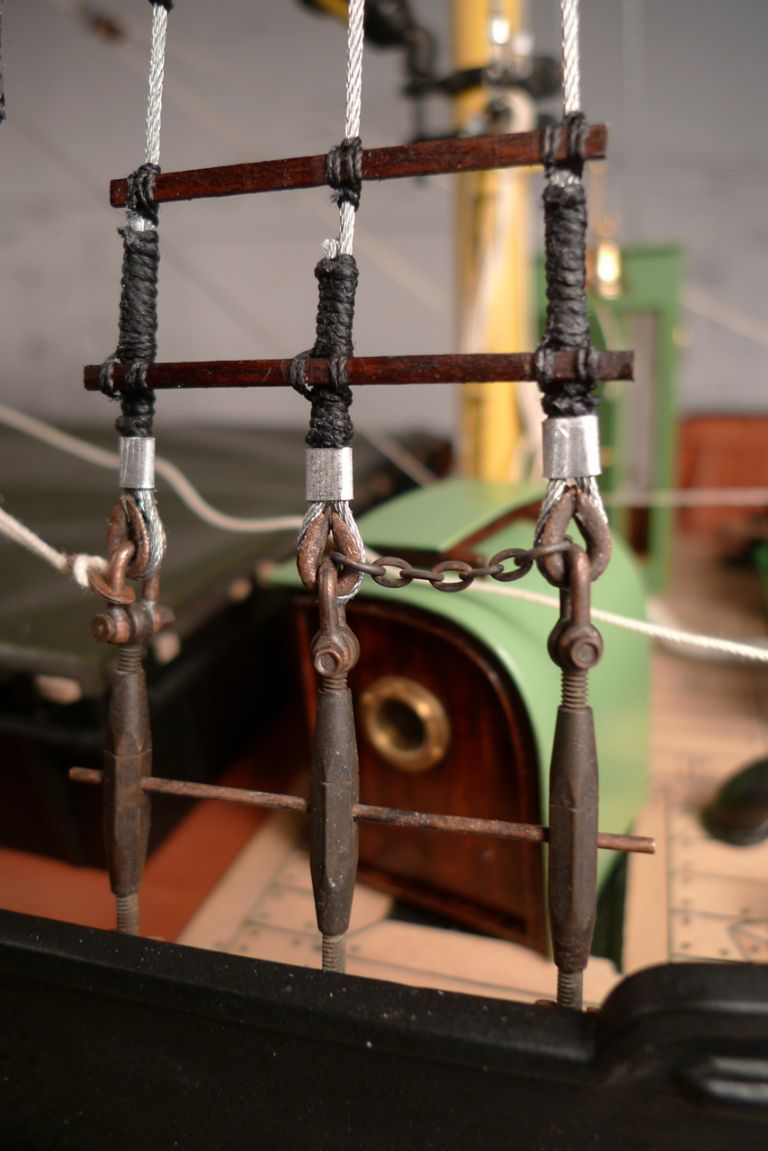
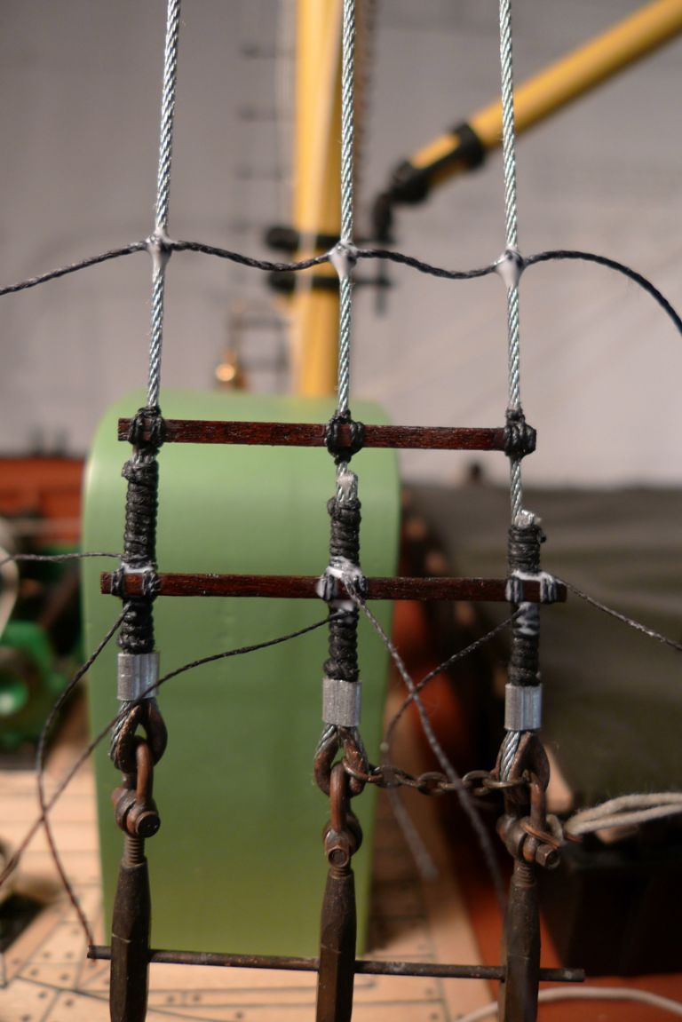
Participant@banjomanNext up were the ratlines to starboard, starting out with just a single one that was carefully distanced from below, tied in place with a series of clove hotches and then had the knots secured with diluted PVA in the usual manner.
Once the PVA had gone off and the first rope ratline sat securely in place, I attached two lattice ratlines below, just above and across the wire end servings. Appart from looking nice, this has the advantage of making the whole chains arrangement more stable, and thus amongst other things also creates a more realistic point of attachment for the guy rope hook.
I had decided to space the ratlines 15 mm apart, which at full size would correspond to 360 mm. Seeing that a stair step is normally somewhere around 180 to 200 mm high, roughly twice that seemed fair enough to me, given that on ratlines the foot does not have to travel both upwards and inwards the way it does on stairs (by the way, a not unfrequently used formula for designing stairs says that 2h+d=630 mm, where h is the height of one step and d its depth).
Anyway, as the lowest lattice ratline sits some 45 mm (= just over one meter to scale) above the bulwark top, I also decided to add a chain step-up to make the ratlines realistically attainable for a crew member by first climbing up onto the bulwark, thence on to the bottlescrew stabilising bar via the chain step-up and onto the ratlines proper.
The reminaing rope ratlines to starboard were then added, five at a time (I find this to be more or less the maximum number that can be correctly spaced with reasonable ease before they've been secured with glue) until the top of the mast had been reached.
To be continued …
/Mattias
Edited By Banjoman on 19/12/2014 07:37:16
19 December 2014 at 08:55 #54439Banjoman
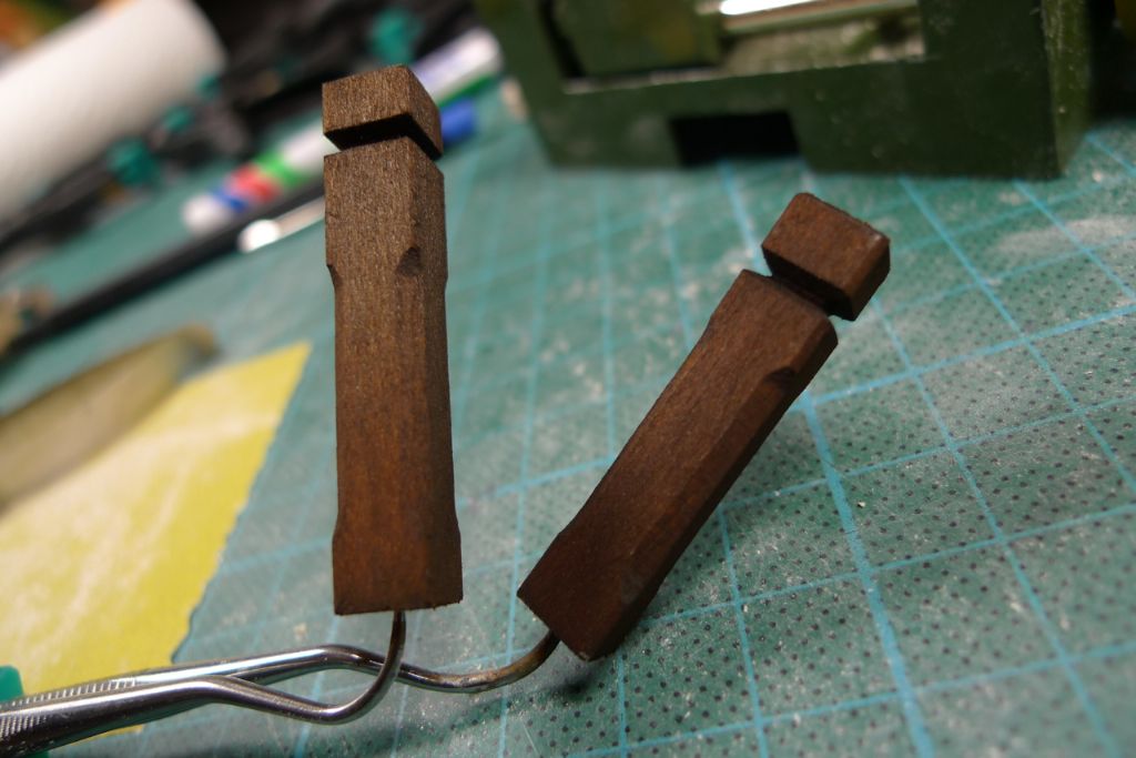
Participant@banjomanI had already made several earlier attempt at making up the four sampson posts for the main deck bulwarks, but each time discarded the results as I'd been less than happy with the shapes achieved. The main problem I had come across was in sanding facets on the lower part corners, where I'd not really managed to make the in all 16 facets sufficiently uniform in size, depth and shape to pass inspection.
After some further thinking about the problem, I came up with a simple but fairly effective sanding jig. I first cut 45 degree obliques (by tilting the bandsaw table) into the edges of a piece of 1.5 mm plywood of appropriate (+/- 20 mm) width. I then glued some 320 grit sandpaper around this piece, which in turn was glued onto another piece of plywood.
This created a shallow sanding block with faced edges. A piece of 4×4 mm distance piece was then glued in perfect parallell with the sanding block. By letting this strip slide against the bottom of the sampson post blank, It was easy to sand all four corners at exactly the same distance from the end of the blank, while the oblique edges of the sanding block created facets that sloped off identically at both ends.
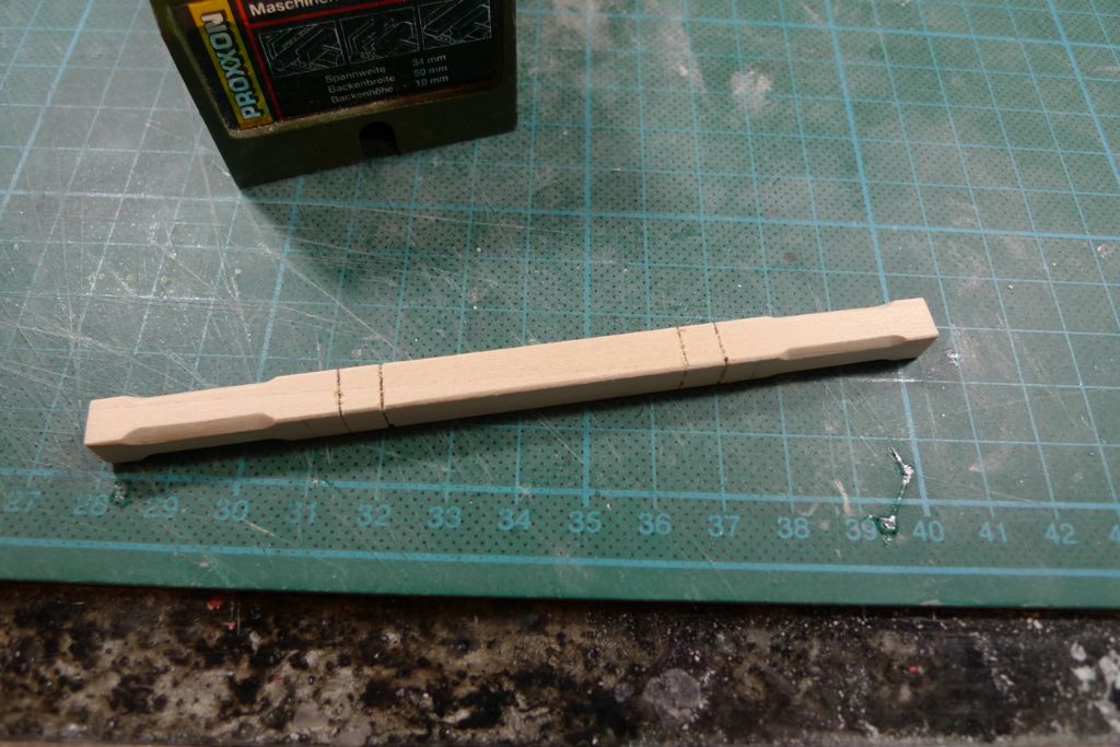
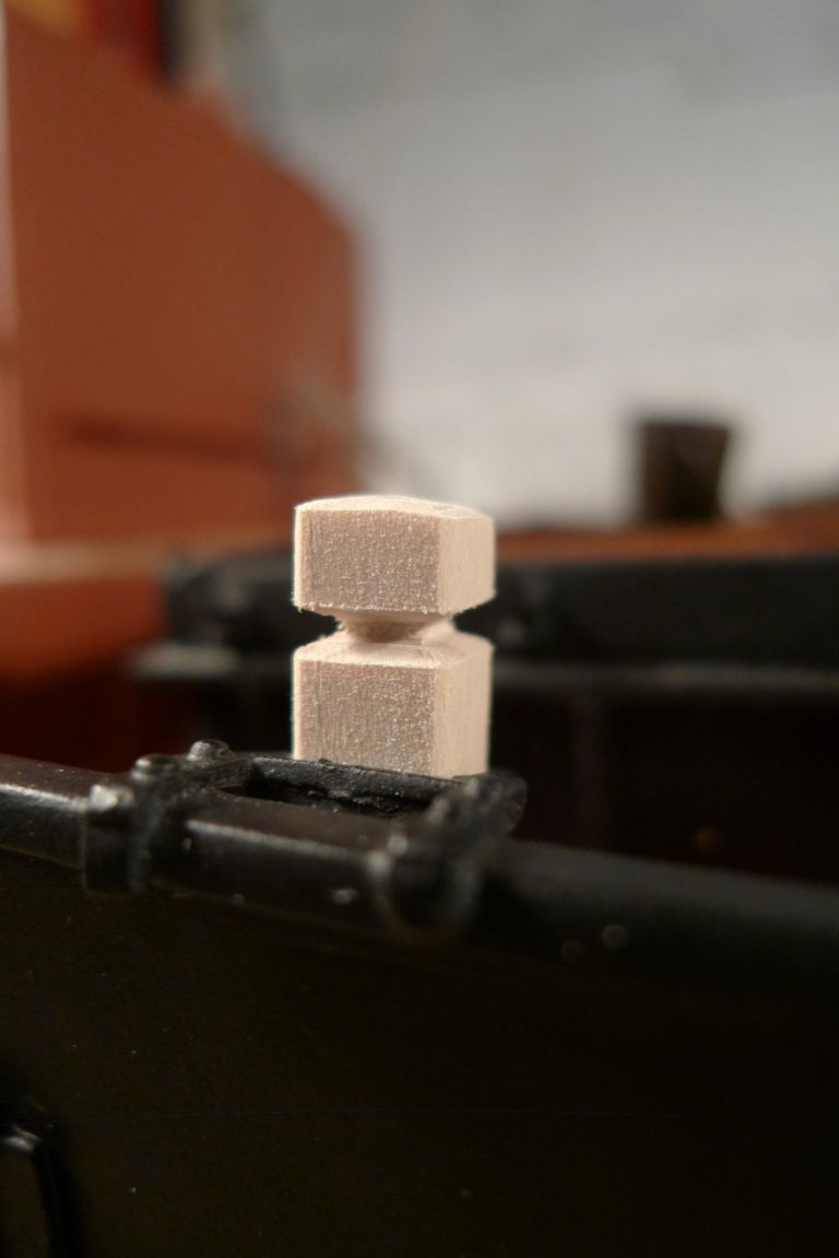
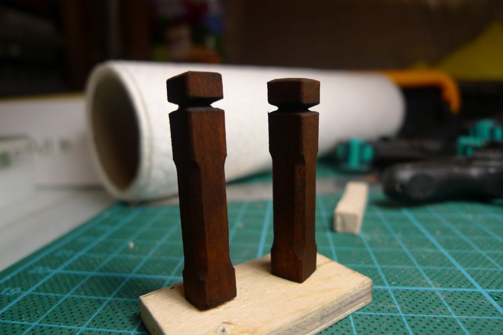
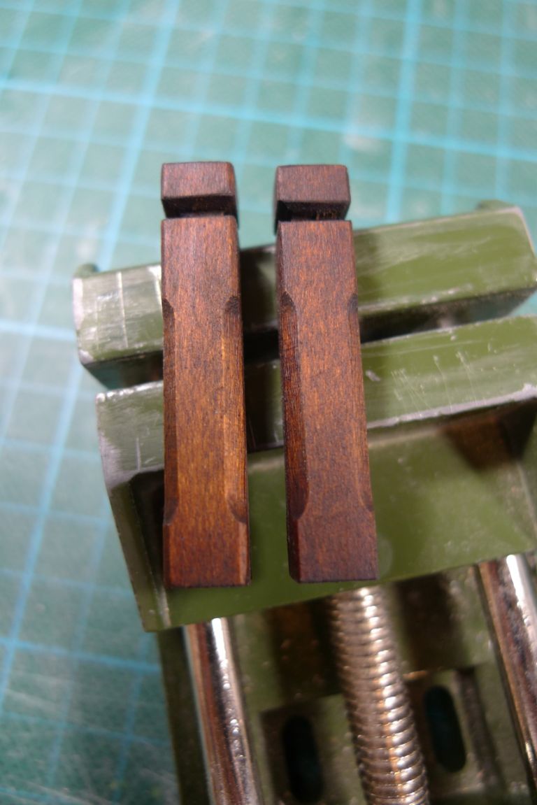
I then used a razor saw and mitre box to cut shallow, squared-off marks around the top ends of the two sampson posts made from each blank …
… and used needle files to create a groove in each top …
… that could serve as a belaying point.
The first two posts were dryfitted on the starboard side …
… and then first stained oak …
… then given a couple of coats of satin varnish …
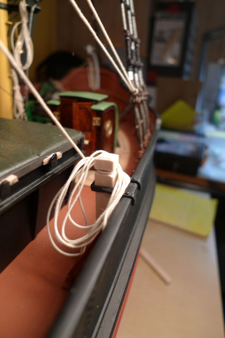
… and finally set in place, with the starboard guy rope made fast to the forrard post.
To be continued …
/Mattias
Edited By Banjoman on 19/12/2014 08:58:01
21 December 2014 at 16:19 #54480Banjoman
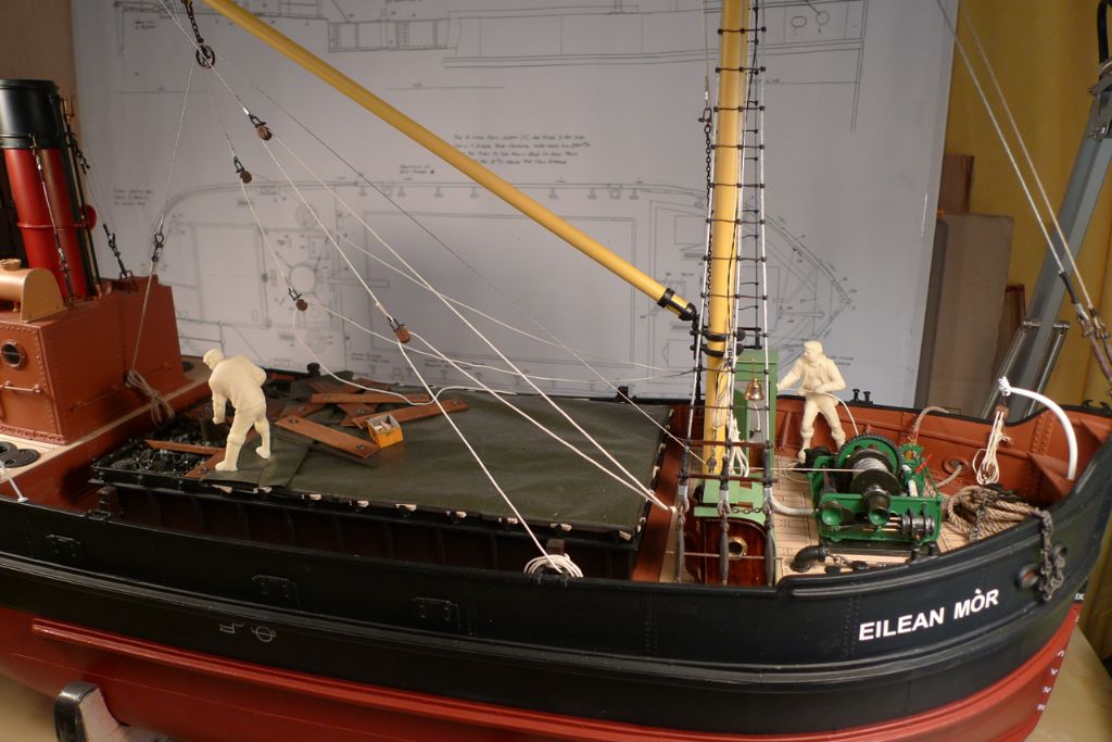
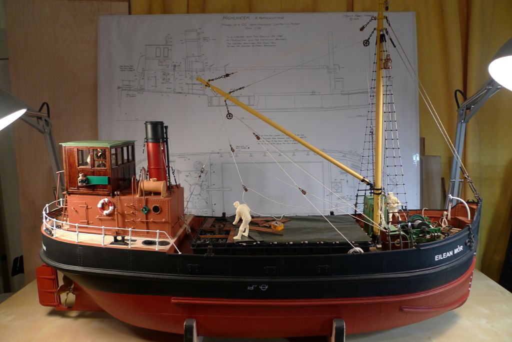
Participant@banjomanHaving been thinking a bit about where and how to place the members of the crew, some further dryfittings seemed lika good idea, once that enough of the deck furniture and paraphernalia was in place to make it clear what might and might not work.
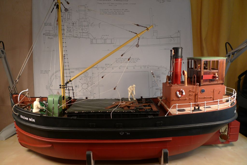
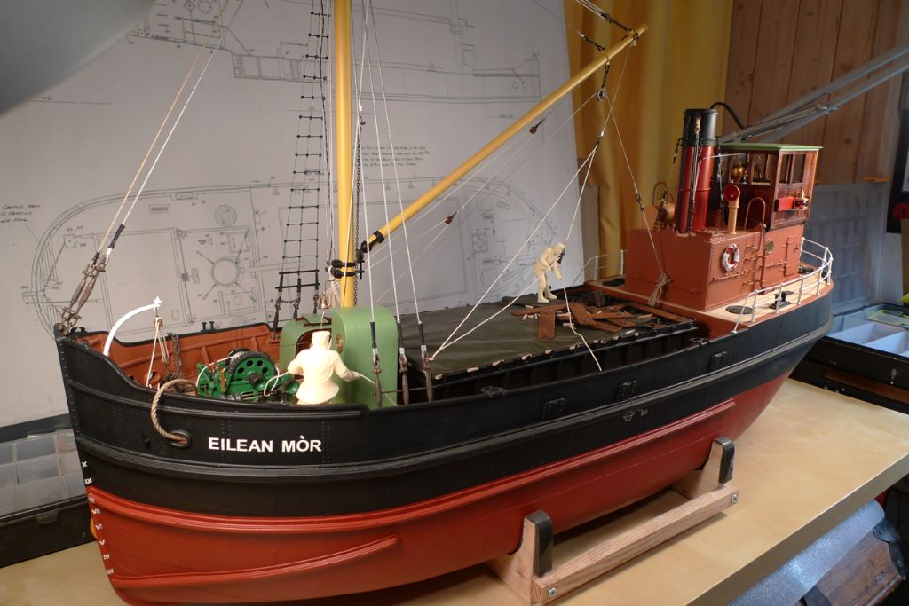
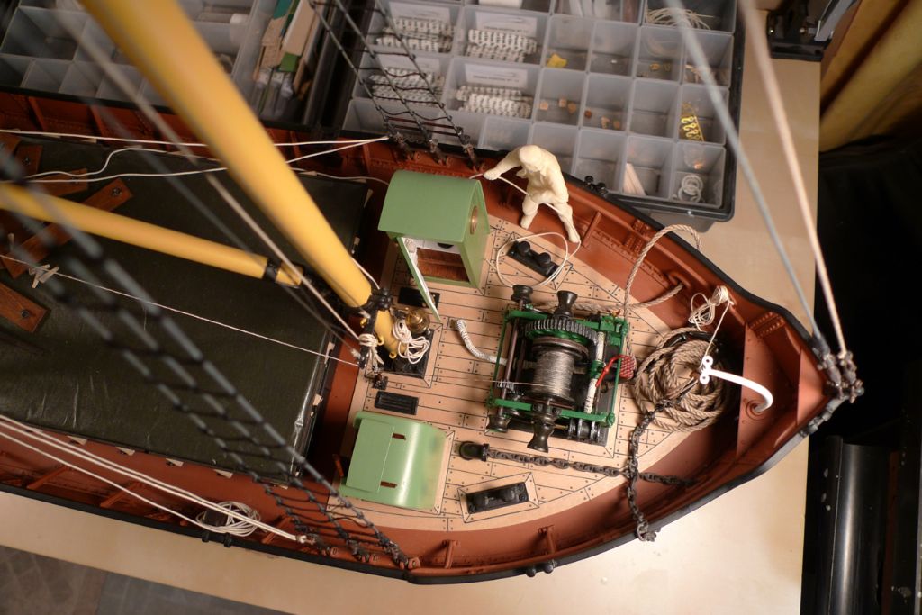
The chosen places would aof course also have to match the poses struck by the figures. As one seemed pretty much made for having a spade or similar shafted implement put into his hands, he was the obvious candidate for the coal pinching job, wheres the next figure, with his hands in a rope-pulling posture, ought rather to be hauling on a rope. I therefore put him on the port side of the foredeck, pulling on the port guy rope.
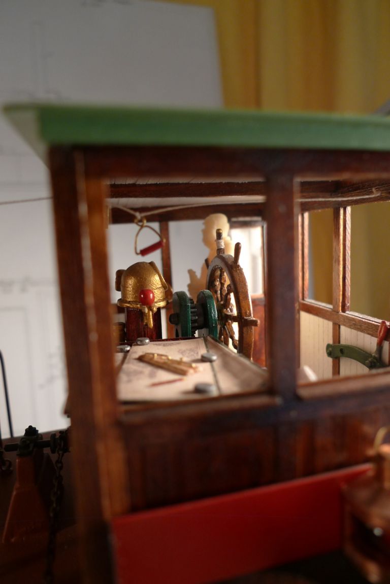
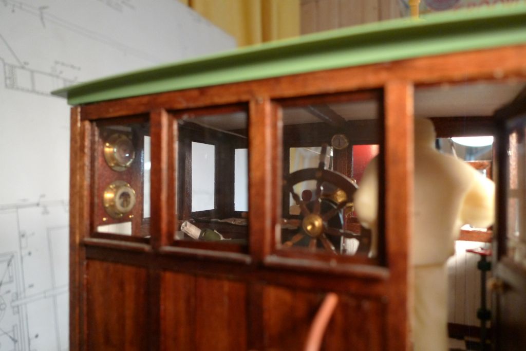
Someone should be at the wheel, too, or at least be in the wheelhouse, and the third figure (as previously mentioned holding a bottle in his left hand) seemed the most suited candidate of the three for this job.
In between playing with the dollies I also made up the port set of sampson posts …
… and began attaching ratlines …
… to the port shrouds.
To be continued …
/Mattias
Edited By Banjoman on 21/12/2014 16:21:20
21 December 2014 at 17:21 #54482Banjoman
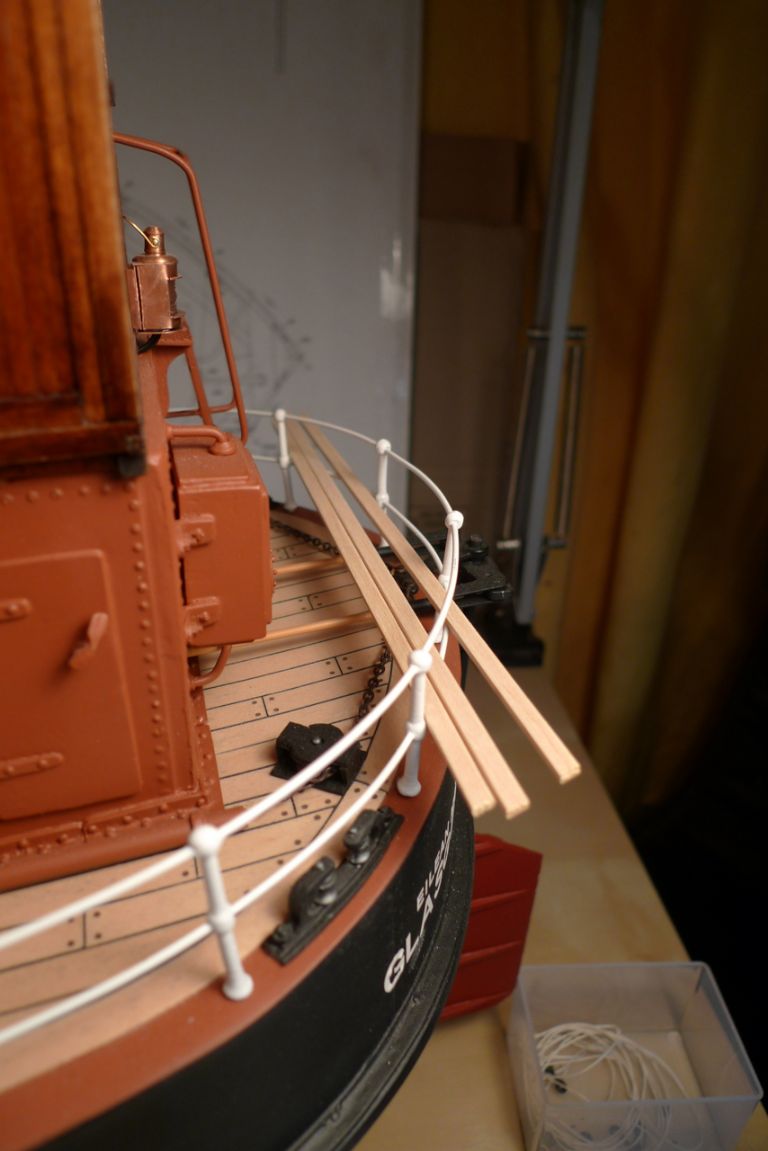
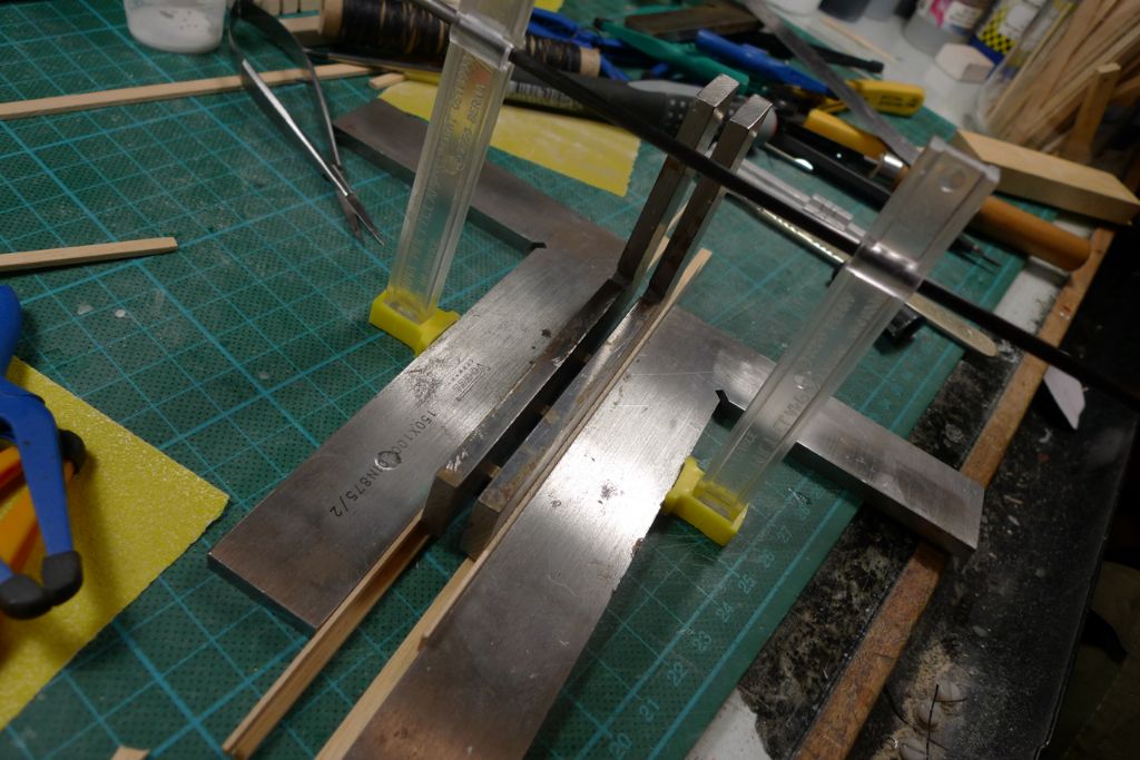
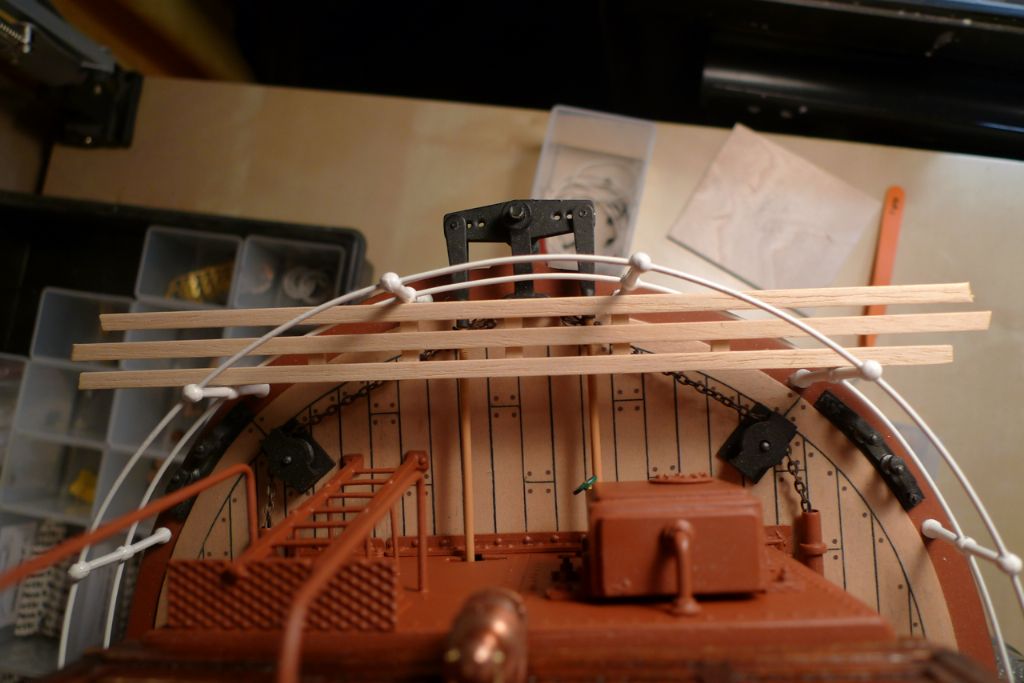
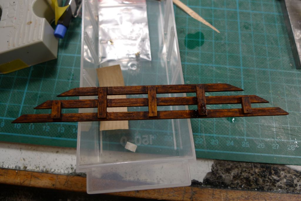
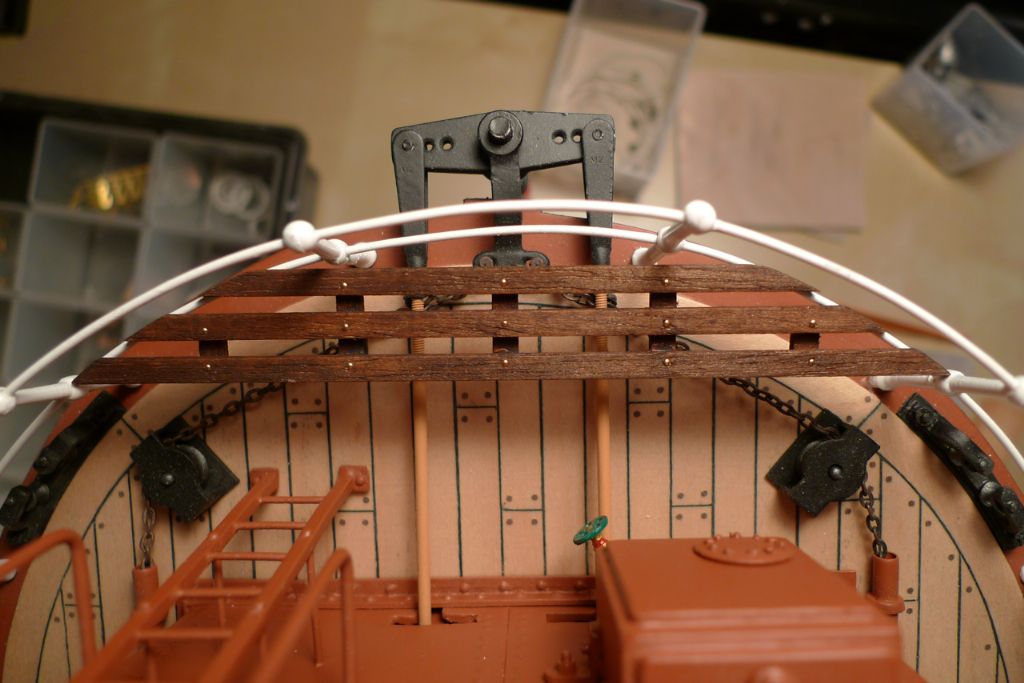
Participant@banjomanI have also sorted out the stern gratings, beginning with three lengths of 2×4 mm lime strip for the grating tops …
… joined together …
… by in total five underlying transversals.
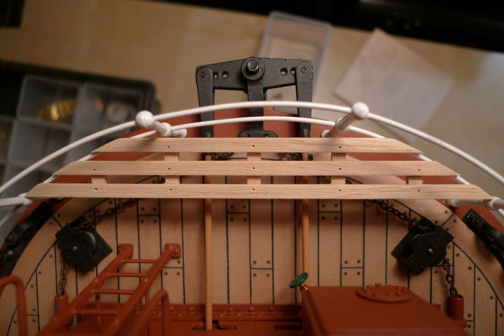
The outside edges were then marked off in line with the lower bulwark rail …
… and cut to shape using the razor blade saw.
Where the the grating tops crossed the transversals, 0.5 mm holes were drilled …
… the whole thing then stained oak …
… and dolls' house brass nails pushed into the holes.
…
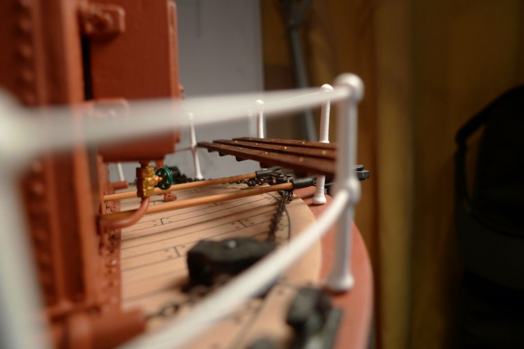
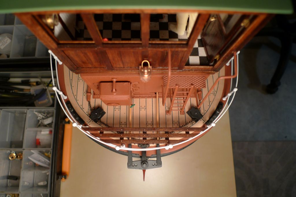
Finally, the finished gratings were given several coats of satin varnish …
… and glued in place with very small quantities of 5 minute epoxy.
To be continued …
/Mattias
Edited By Banjoman on 21/12/2014 17:22:42
Edited By Banjoman on 21/12/2014 17:23:04
21 December 2014 at 20:59 #54485 Colin BishopModerator@colinbishop34627
You have a beautiful model there Mattias. You could almost just step aboard.
Colin
21 December 2014 at 21:54 #54487Bob Abell 2
Participant@bobabell2Lovely model, Banjo……The finest I've ever seen!
Could I make a small suggestion, please?
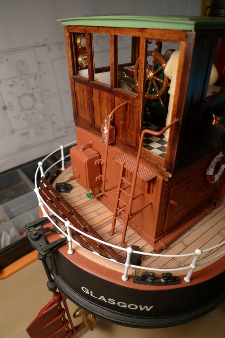
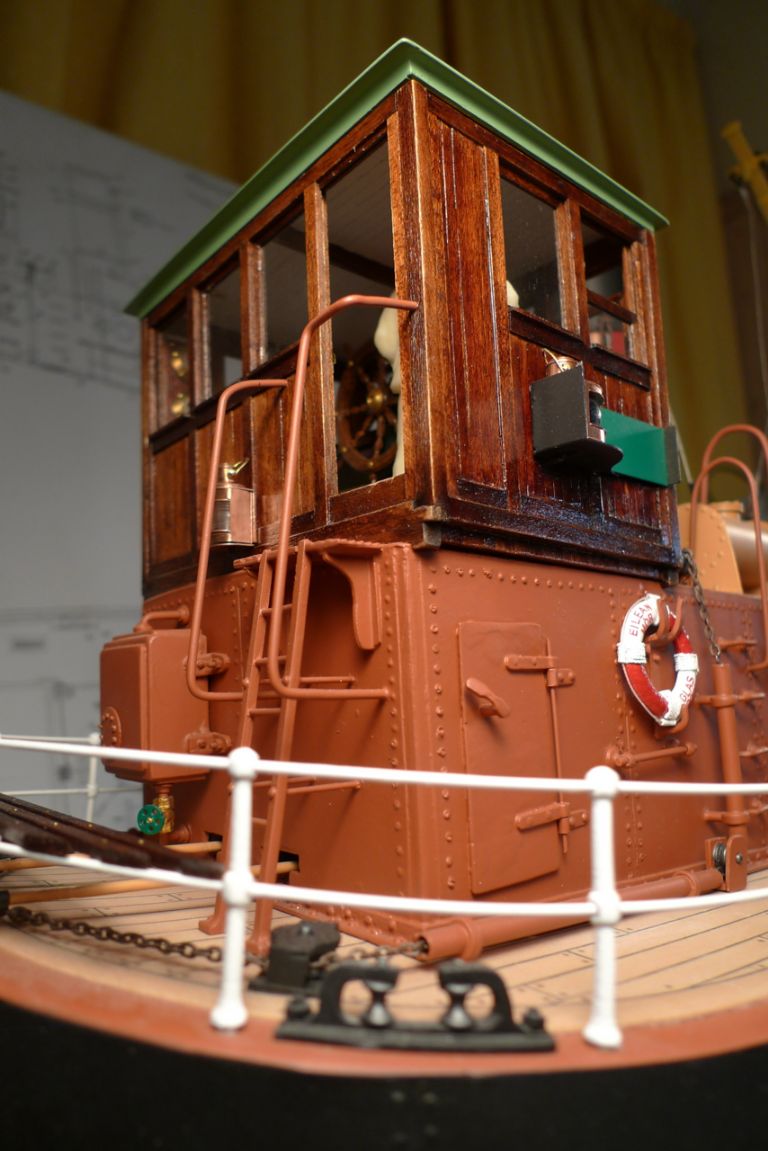
On the last photo, showing the chequer plate and ladder…….What about a touch of silver paint to indicate wear?
Sorry to be a busy body
Bob
22 December 2014 at 10:53 #54494Banjoman
Participant@banjomanThank you very much indeed, Colin and Bob, for your kind words!
Thank you, too, Bob, for your suggestion about adding some wear to the wheelhouse ladder and step plate. Believe me, this is something which I've been debating with myself ever since I began the build: whether or not to weather! Whether 'tis nobler to let your model show it suffered the slings and arrows of outrageous fortune, or to preserve in that pristine state in which it once came off the wharf … ?!?
As I think I've already mentioned before in this thread, I have been very hesitant to go down the weathering route, mainly because it is something of which I have very little experience, and thus do not quite dare to start applying for fear of ruining a 1,000-hour build. Of course I feel confident that I could add a few wear effects to the checker plate – I've already done as much with the winch brake pedal, and found it quite easy, using a silver pencil and some oil paint.
In spite of this I still very much hesitate, for the again fairly simple reason that once I start weathering something else, like for instance the wheelhouse checker plate and ladder, there will be something next to this that now will look even more too pristine, and thus requires weathering in its turn, and so on and so forth.
In other words: weathering can very quickly become an all-or-nothing-at-all game, so with the very minor exception of the winch, I have so far stayed away from it.
I may yet change my mind, but that'll have to wait until the whole model has been completed, and I can make up a fully thought through and complete weathering plan for the whole ship. And before I do that, I want to see what I am able to achieve, weathering-wise, on a simpler model (as also mentioned before, I have a 1:24 ca 1970 Renault 4L plastic kit sitting around that bought with the express purpose of trying my hand at weathering).
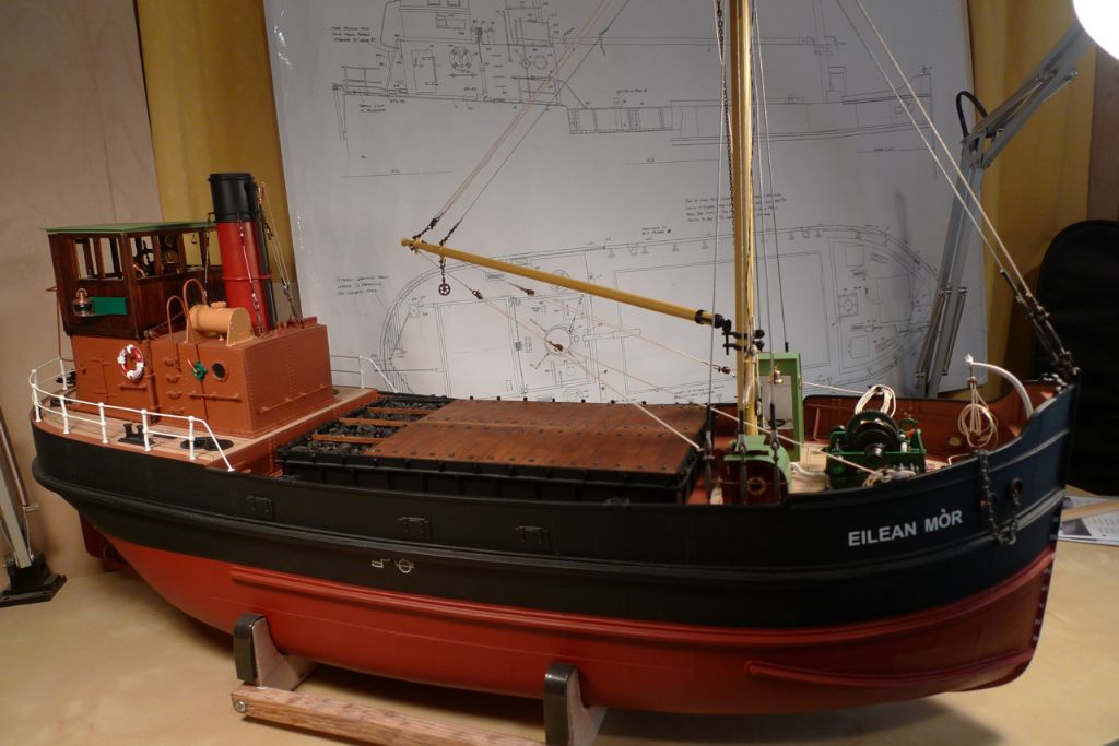
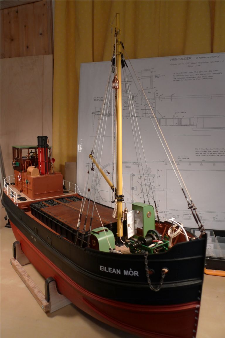
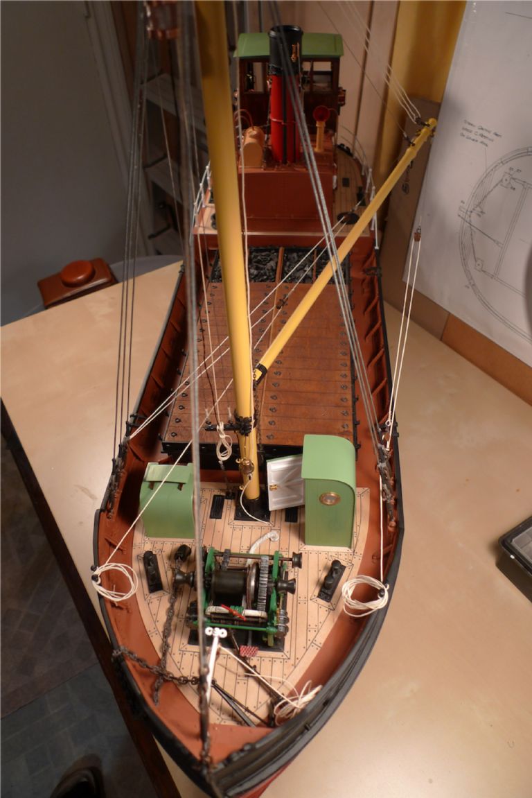
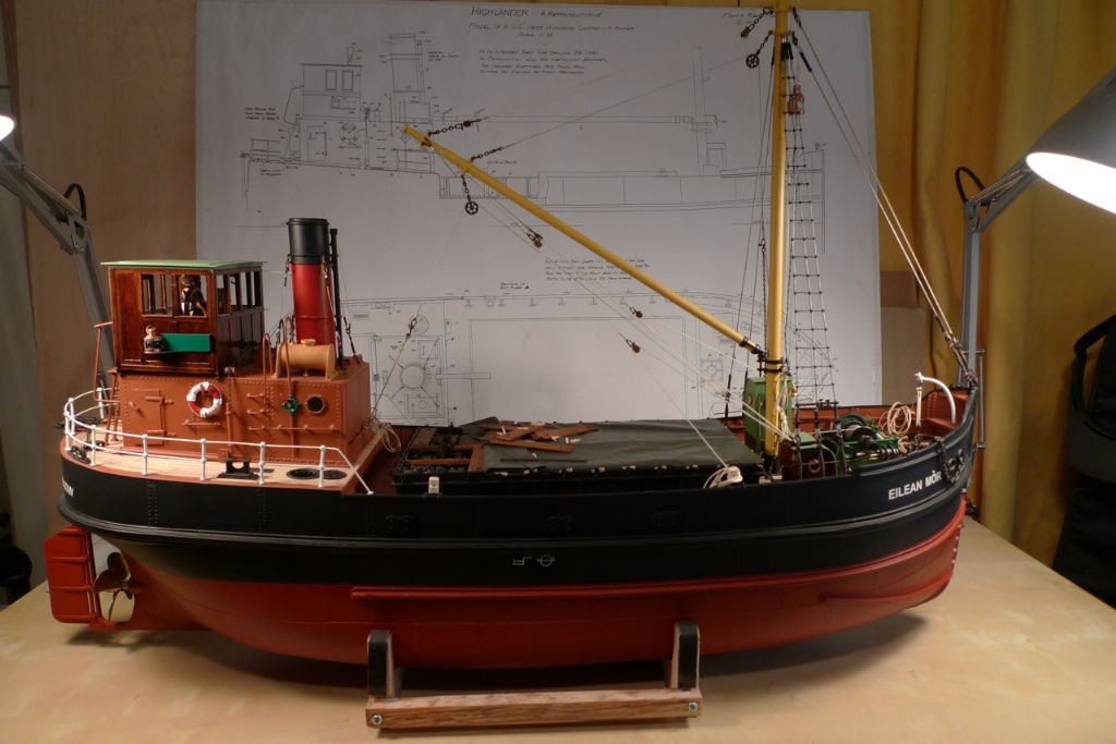
Anyway, here follows a few more picture that bring this thread up to the present: these are the very last things I've done on the model so far, and further reports will thus no longer be retrospective but come as and when I continue building.
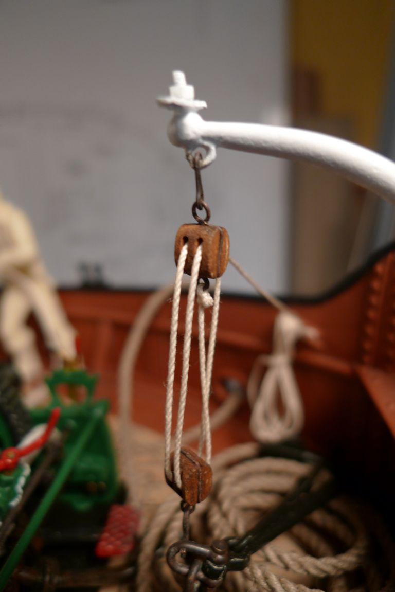
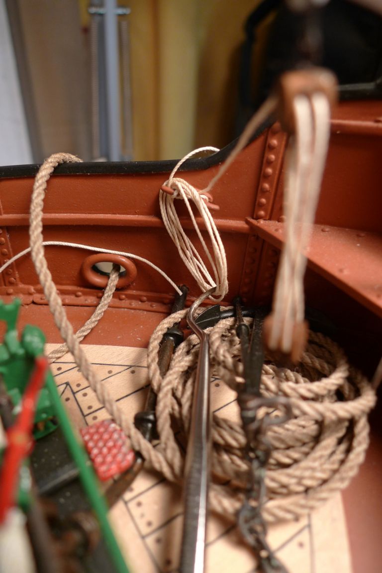
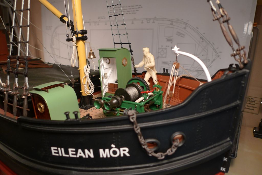
The anchor davit double tackle has been slightly re-rigged: when first setting it up, I had not yet added an eye to the top block arse, and therefore made fast the standing end of the tackle around the shank of the upper eye. The other day, I finally got around to sorting this out …
… and could then also belay and coil the running end …
… in a slightly more permanent fashion.
I also did some more work on cleaning up the resin cast crew figures …
… including drilling out the fists of the chap hauling on a rope, so that said rope might actullay look as though he's holding on to it.
To be continued …
/Mattias
Edited By Banjoman on 22/12/2014 10:54:13
Edited By Banjoman on 22/12/2014 10:54:53
22 December 2014 at 11:06 #54495Bob Abell 2
Participant@bobabell2Hello Banjo
I did suspect that the weathering idea would cause you a head spinning delemma
What camera are you using, for these excellent close up shots?
Bob
22 December 2014 at 11:18 #54496Banjoman
Participant@banjomanYup, Bob – as yet I'm dithering rather than weathering; we'll have to see if I ever man up enough to get down and dirty wif me model …

As for the camera, I'm using a Leica digital compact, the D-Lux 4 (see for example **LINK**) since replaced, I believe, by the D-Lux 6 (**LINK**).
/Mattias
Edited By Banjoman on 22/12/2014 11:18:31
22 December 2014 at 12:40 #54497 Colin BishopModerator@colinbishop34627
Mattias,
If in doubt, don't! Whether to weather your model is a very personal thing, some love it, others do not. But if you do go down that route then, as you quite rightly point out, it's all or nothing and a badly weathered model looks a mess. It does take a lot of skill to get right.
My personal preference is not to weather as I like my models to appear as if they have just been completed but that is just they way I like it and I think that is generally the majority view at most of the shows I go to. Having put all that effort into getting a good finish, why make it dirty unless that was the intention right from the start.
Weathering done well can be very effective but frequently it isn't done well! It is literally an art in itself!
Colin
22 December 2014 at 20:00 #54514Banjoman
Participant@banjomanColin,
I think I know rather well what you mean when you say that you prefer your models to have that just-completed look – I too have previously always belonged to that school of model boaters, although a well-weathered model is indeed a thing of beauty in its own right.
Well, we'll see – as I've already said, I'll have to give this one a very hard and very long and very thorough think-through (and do some serious off-model test weathering) before I break out any dirt, stains or wear … if ever I do; the odds are currently stacked against rather than for, I'd say …
/Mattias
25 December 2014 at 14:53 #54560Banjoman
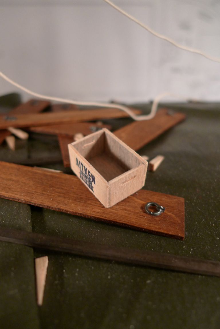
Participant@banjomanOver the last couple of days, I've put in some tome towards making up an empty beer crate, based on one from tje collections of the Falkirk Museum (**LINK**).
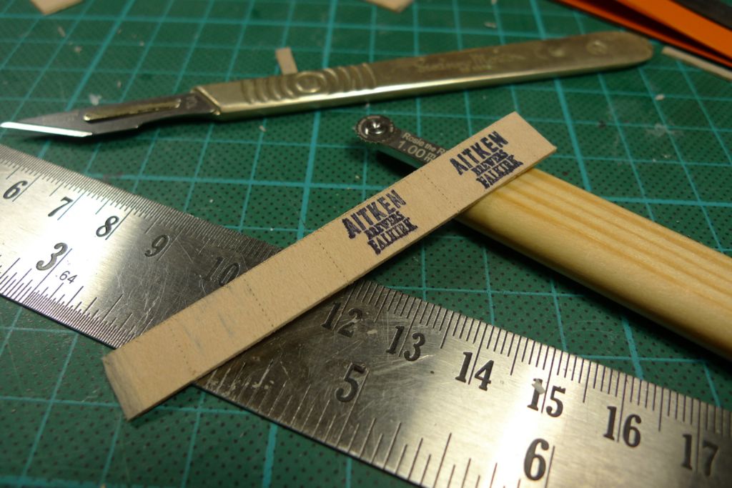
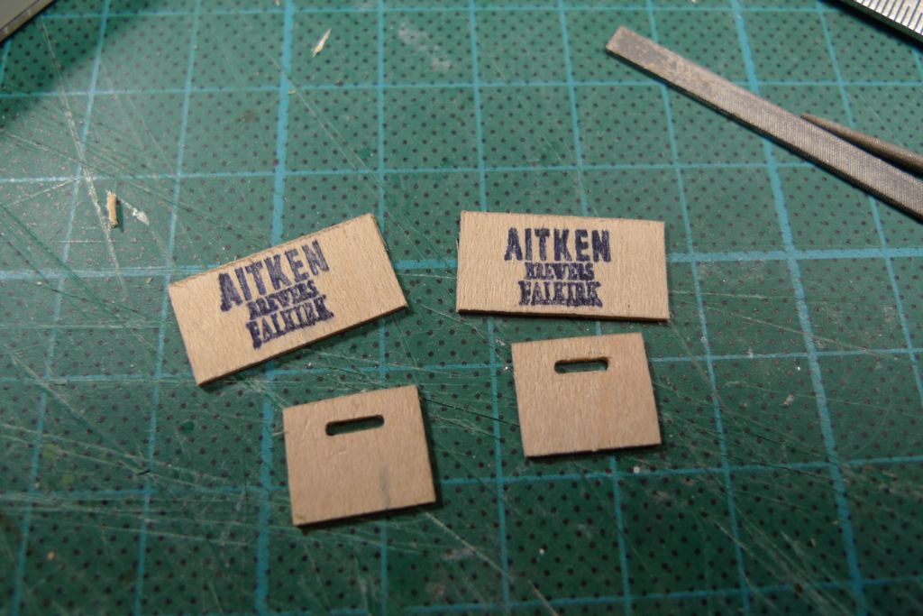
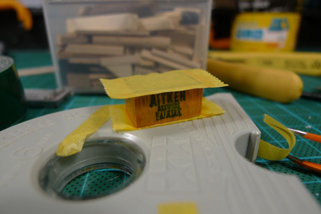
I began by marking out the four sides on a 10 mm wide strip of 1 mm maple sheet (that had been greyed with a couple of coats of Weather-it on the reverse) and also stamping the Aitken Breweries logotype on the two longer sides.
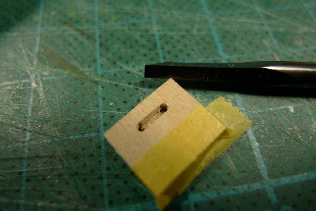
The two short side blanks were taped together, two 1.2 mm holes drilled and the wood in between cut out …
… and filed to form handle openings.
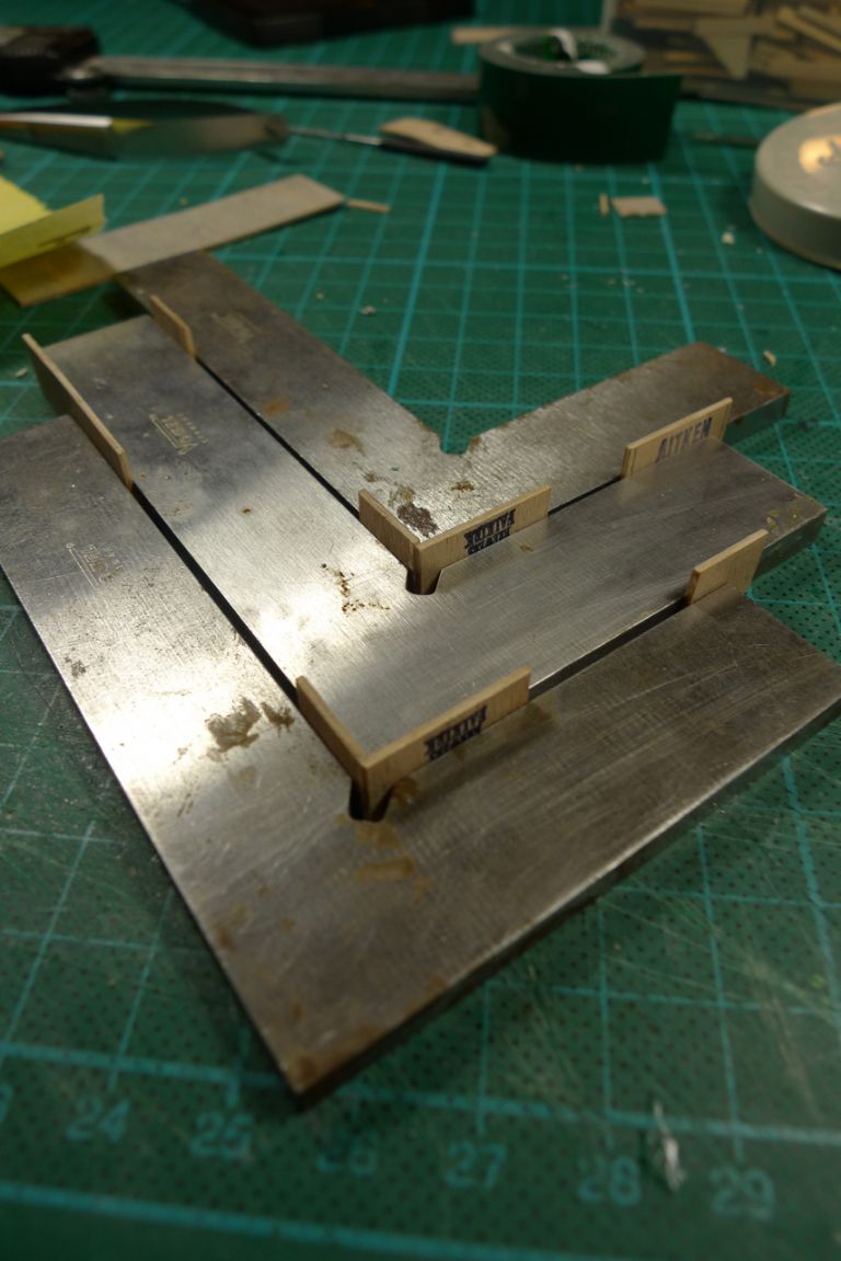
One short side was then glued to one long side, and, once the glue had gone off …
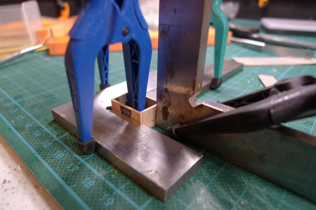
… all four sides were joined together.
Next a bottom was cut out and glued in place …
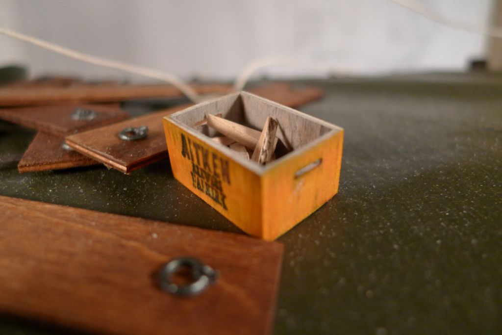
… after which the crate was sanded down and the sides painted in a mix of five parts satin varnish to one part 62.004 Orange paint.
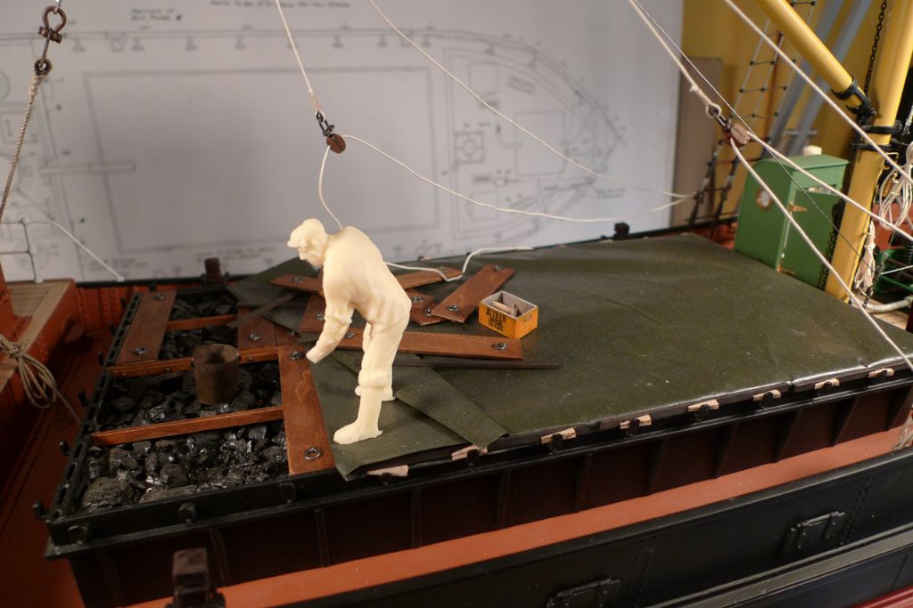
The final result looks iike this, with the loose battening wedges thrown in for safe keeping …
… while the deckhand is pilfering coal …
… from the main cargo.
To be continued …
/Mattias
Edited By Banjoman on 25/12/2014 14:54:28
Edited By Banjoman on 25/12/2014 14:55:35
25 December 2014 at 14:57 #54561Banjoman
Participant@banjoman25 December 2014 at 18:39 #54562Bob Abell 2
Participant@bobabell2Many thanks and the same to you and yours, Banjo
Your thread has made a nice Christmas present for us all and has raised the level of the game to a dizzy height!
Congratulations from all of us
Bob
26 December 2014 at 20:55 #54571Banjoman
Participant@banjomanThank you very much, Bob!

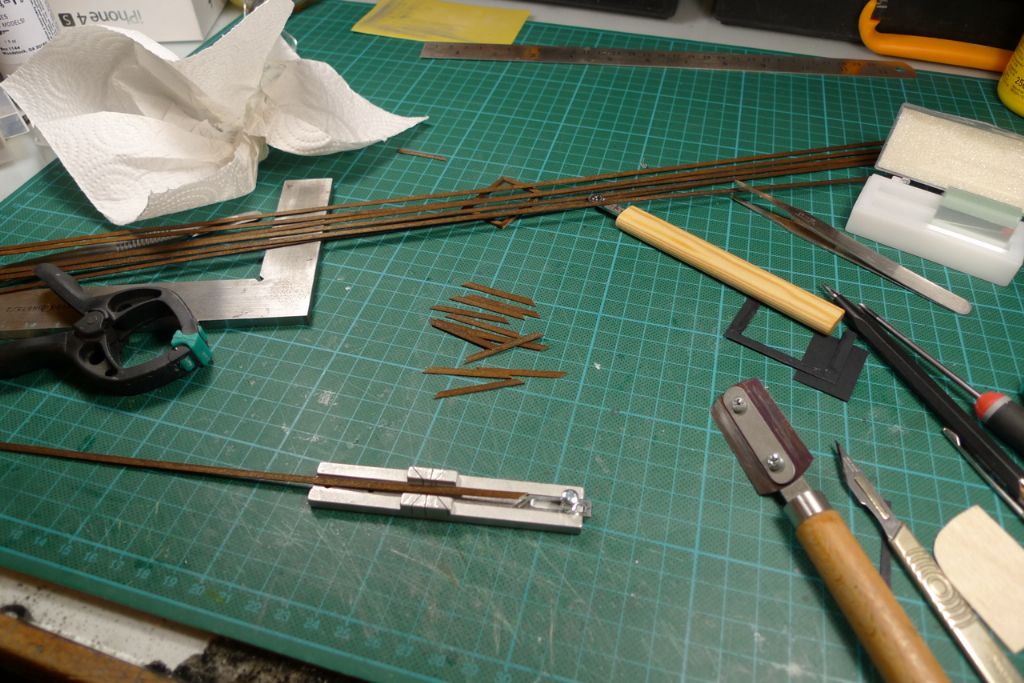
I've now made a start opn the wheelhouse windows; first by staining 4 metres of 0.5×3 mm maple strip a dark oak colour; here these have been hung up to dry overnight. Given that the stain makes the wood expand, and that the initial glue joints will be quite weak, I figured it would be better to stain first to avoid the risk of the expanding wood breaking any glue joints.
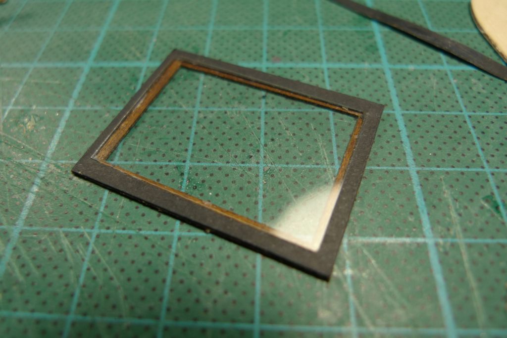
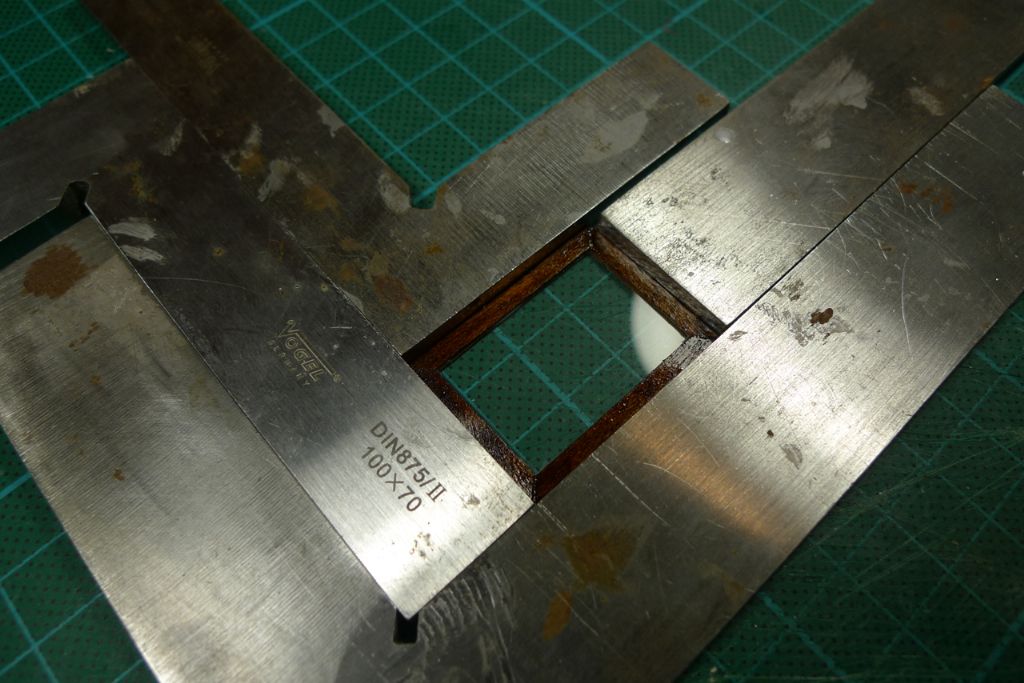
Before starting mass production (I will need 12 windows), I first made up a quick test piece, glueing together a back and a front windowframe, and cutting out a pane size hole in some black cartridge paper.
The paper was then glued to the first frame, trimmed to size along the outer edges, and a pane of glass inserted in the middle. The panes are real glass – 22×32 mm microscopy slide covers approximately 0.17 mm thick, i.e. more or less to scale.
The second frame was then glued on top of this to create a window sandwich …
… that looked like this when test fitted in a closed position …
… and like this when installed half-open.
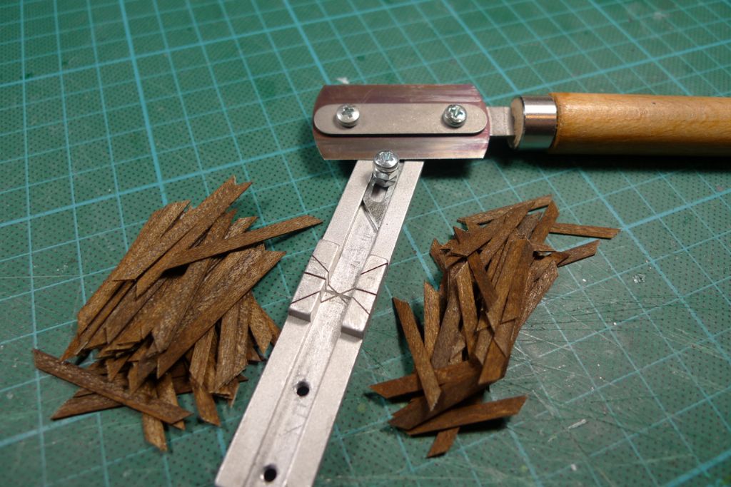
Once the dimensions had been properly verified, it was time to start cutting out all the pieces of strip to make up the frames …
… in total 48 verticals and 48 horizontals (plus a couple of spares). The micro mitre box and razor blade saw are very handy for this sort of job, as the mitre box has a built-in adjustable stop, one end of which is set at a 45 degree angle.
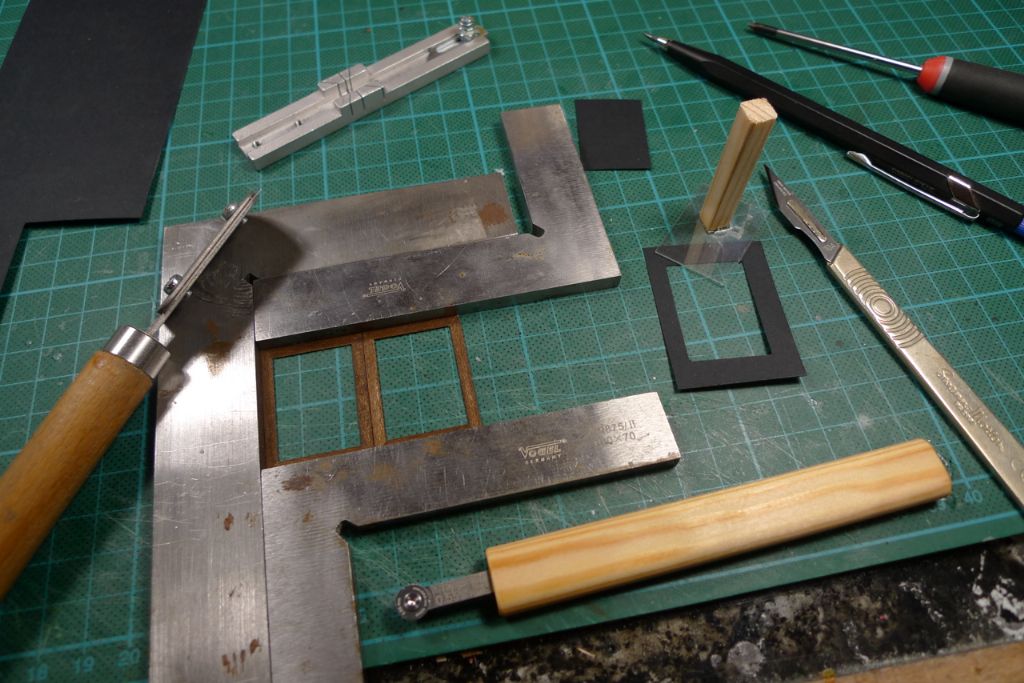
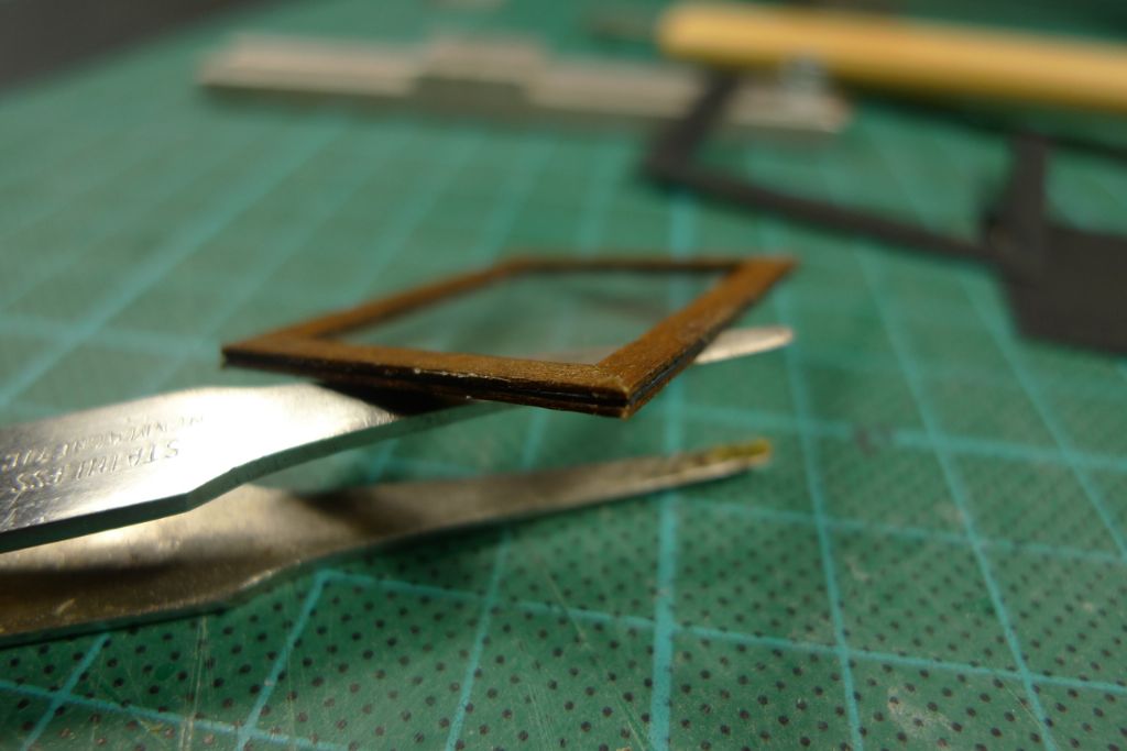
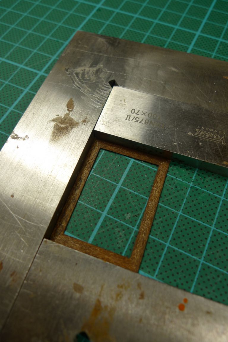
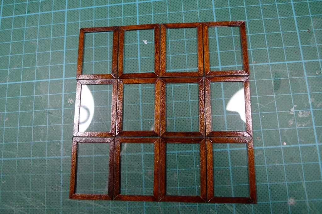
Verticals and horizontals were then glued together, using a couple of try-squares to ensure correct alignment.
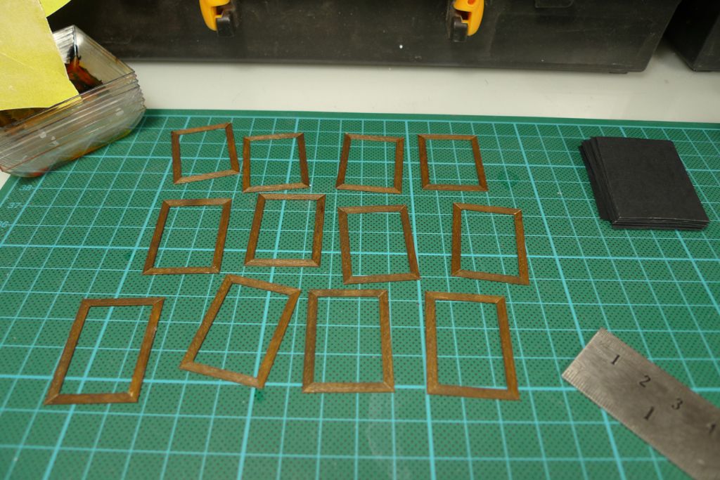
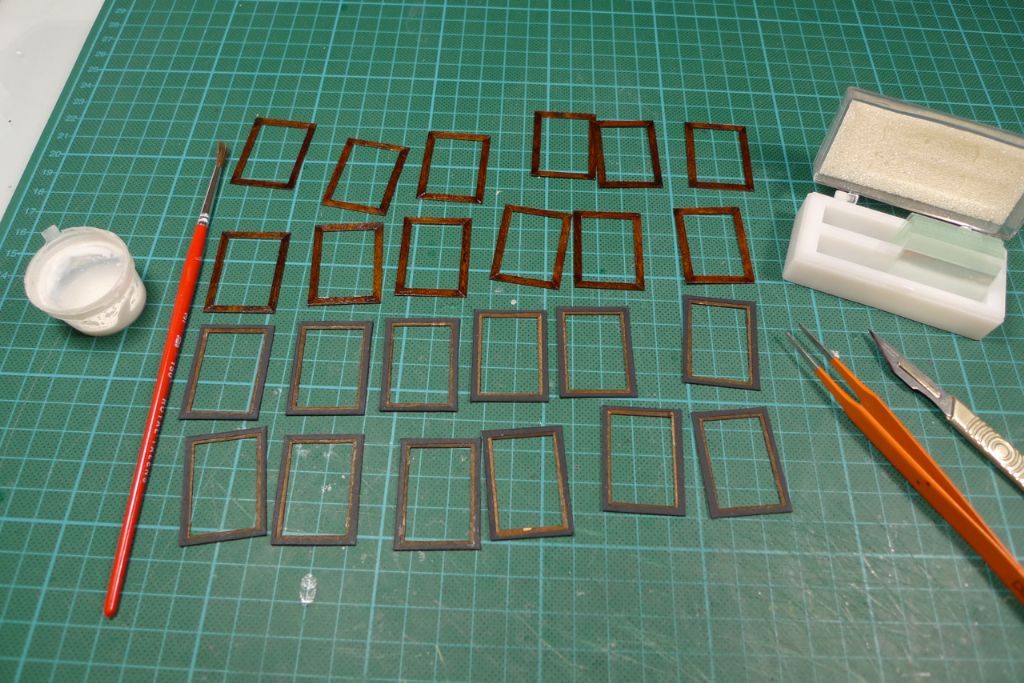
All in all, I will need 24 frames; in the picture below are the first 12. The second batch has since also been made up, and once the joints are fully cured tomorrow, I shall touch up the staining as and if necessary, and then spray one side of each frame with the same gloss varnish that I used for the wheelhouse itself.
To be continued …
/Mattias
Edited By Banjoman on 26/12/2014 20:56:06
Edited By Banjoman on 26/12/2014 20:57:10
Edited By Banjoman on 26/12/2014 20:59:00
27 December 2014 at 16:48 #54589Banjoman
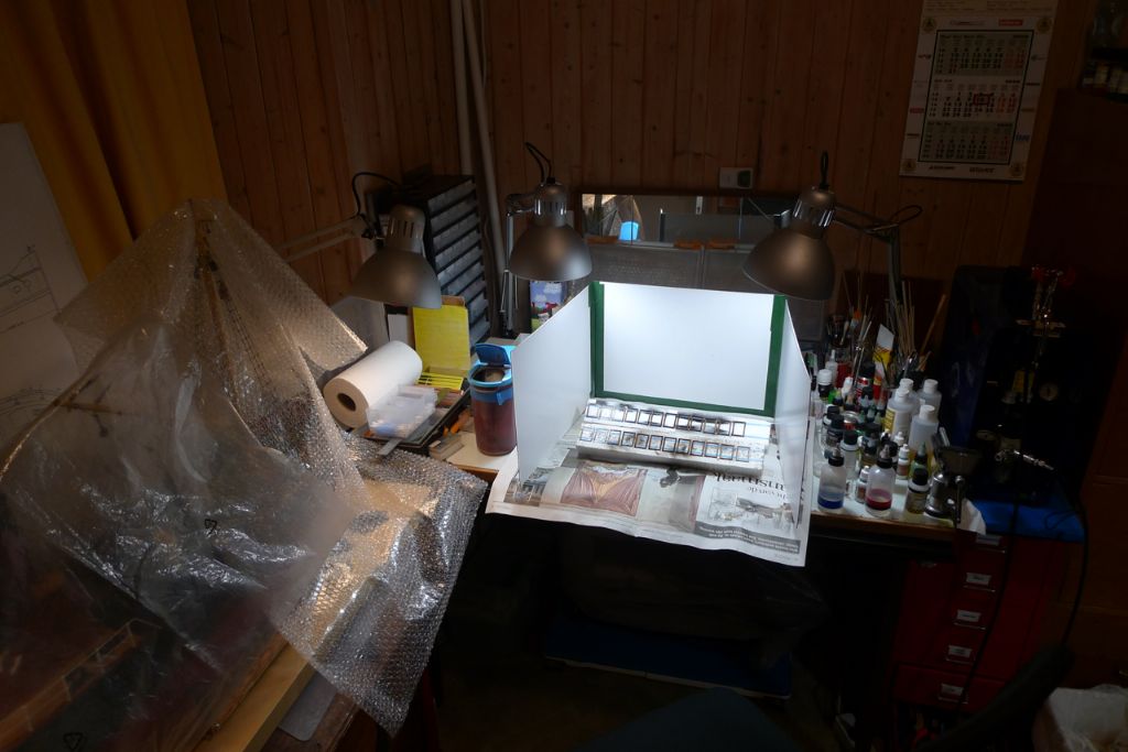
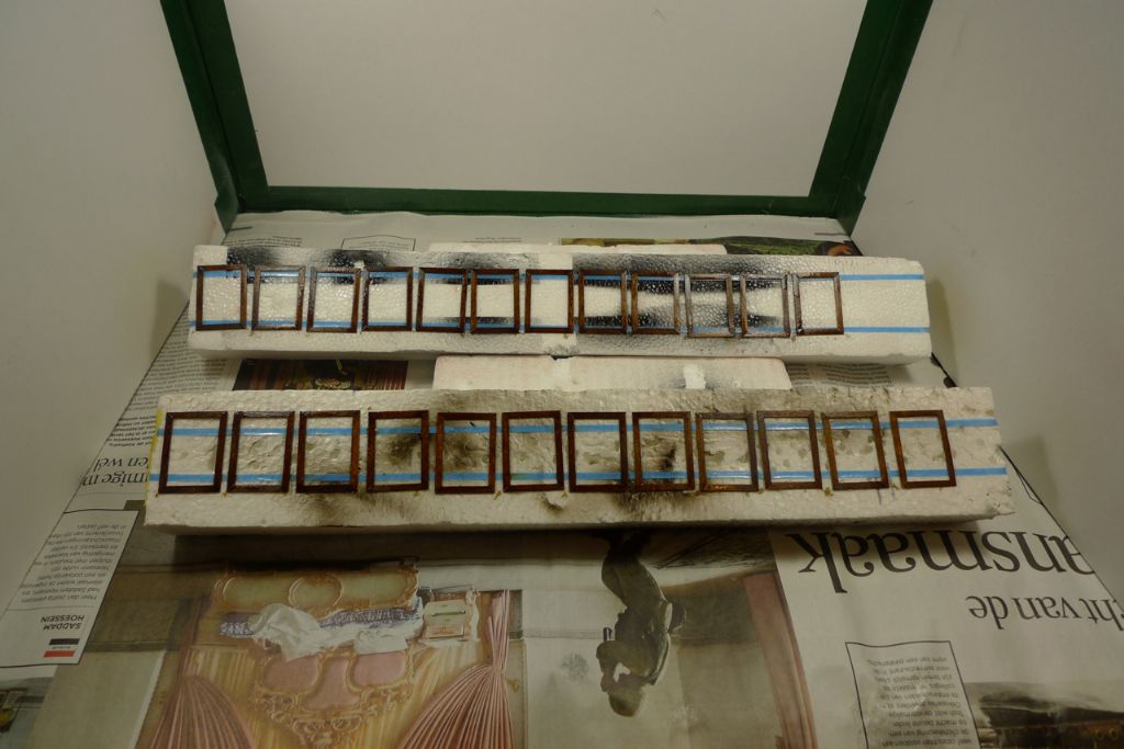
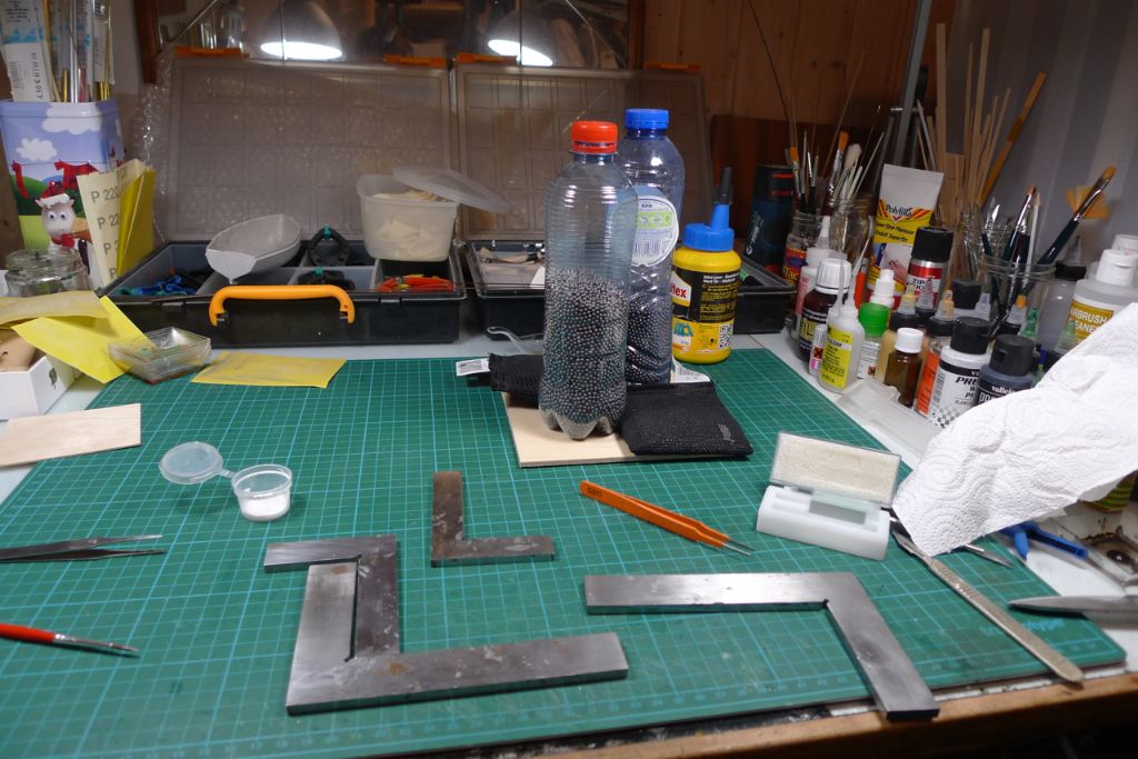
Participant@banjomanThis morning, I set up the smaller of my two spray boxes, and got out the airbrush …
… to give the wheelhouse window frames a few coats of clear varnish on what will be their visible faces.
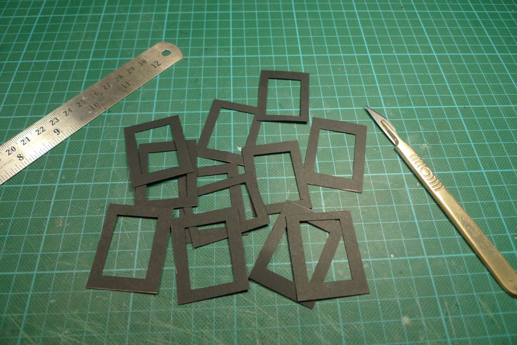
These were then set aside to dry, while I cut out the middles of the cartridge paper inlays.
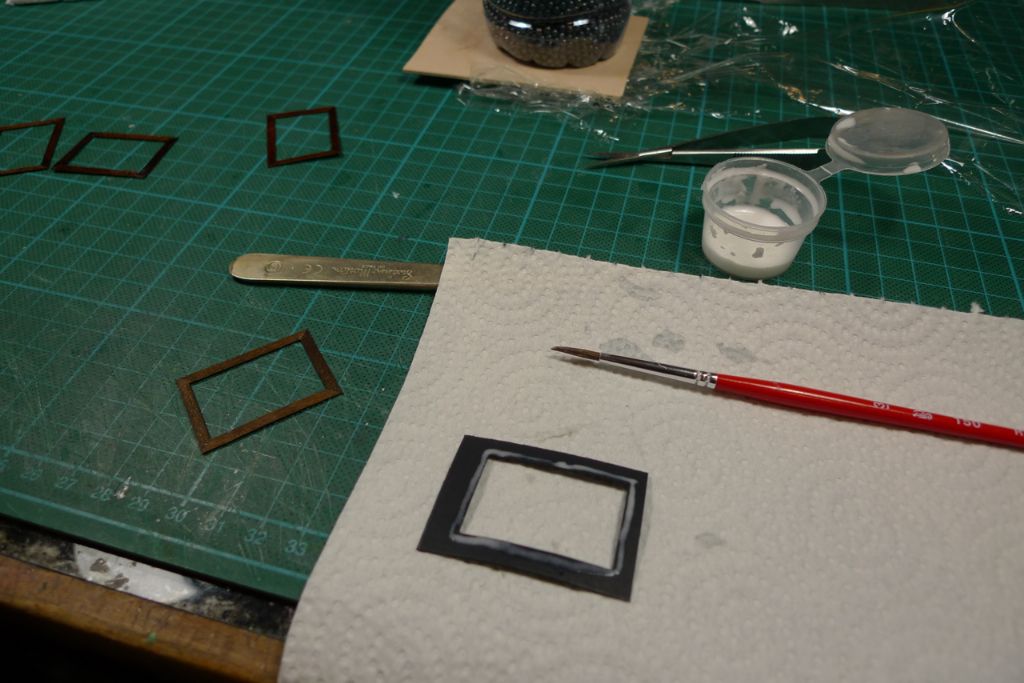
Once the varnish was fully cured, the inlays were glued to the first of the two window frames, using watered-down PVA.
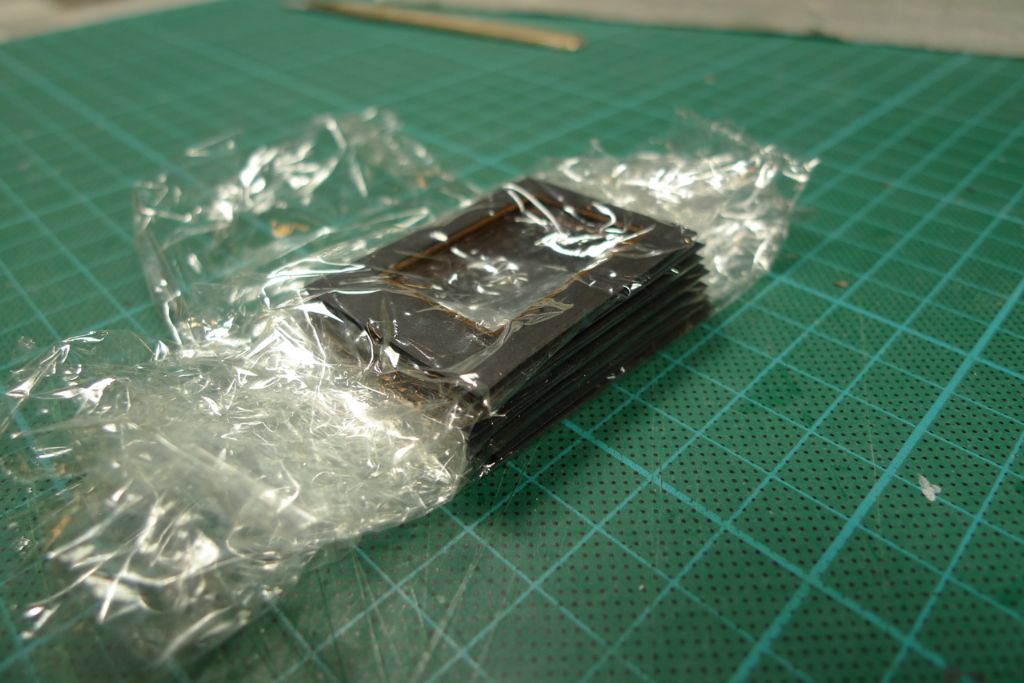
These assemblies were then stacked (with clingfilm between each to prevent them from sticking to each other in case of an excess of glue) …
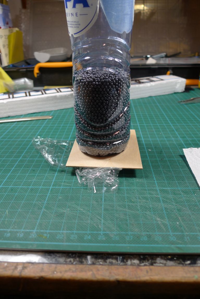
… and set in press for the glue to dry.
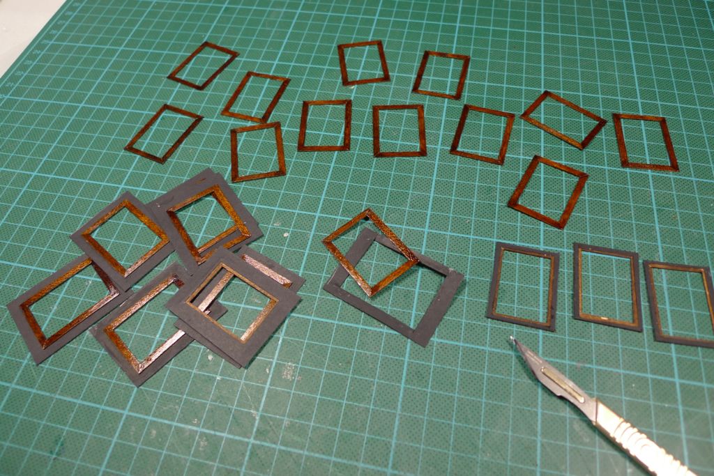
Once the diluted PVA had gone off, the excess cartridge paper was trimmed away …
… leaving me with 24 frame halves and ready to start glazing!
A pane of glass was inserted in the middle of each paper inlay, and the top frame half glued down, again with diluted PVA. As usual, some try squares came in handy for aligning each set of frames …
… which were then all put under a piece of plywood and set in press to dry.
To be continued …
/Mattias
Edited By Banjoman on 27/12/2014 16:50:21
30 December 2014 at 22:58 #54668Banjoman
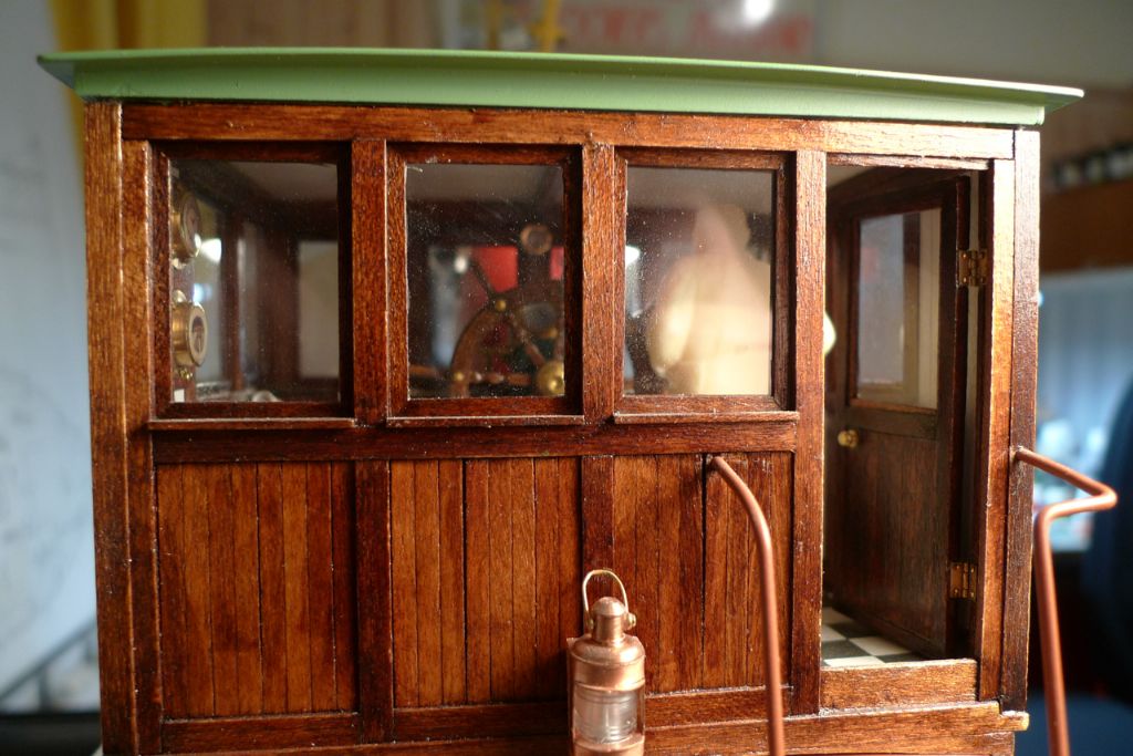
Participant@banjomanWhen the glue had set, I had twelve finished windows …
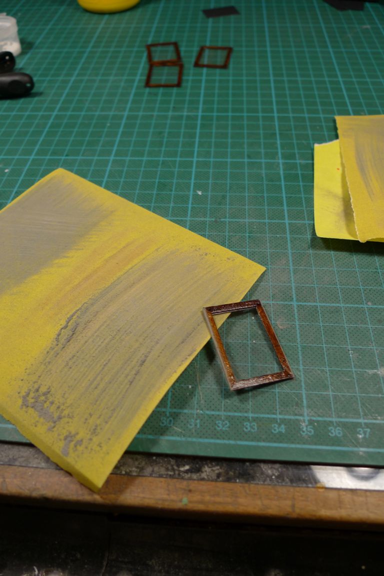
… that, after a final sanding down of the vertical edges …
… were ready to go into their slots in the wheelhouse window openings.
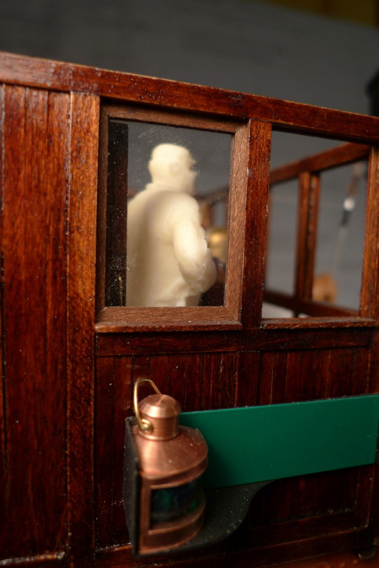
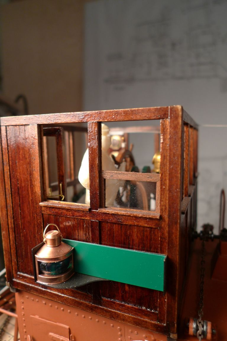
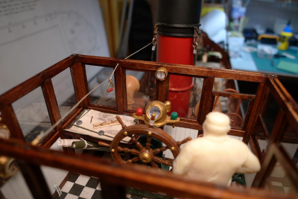
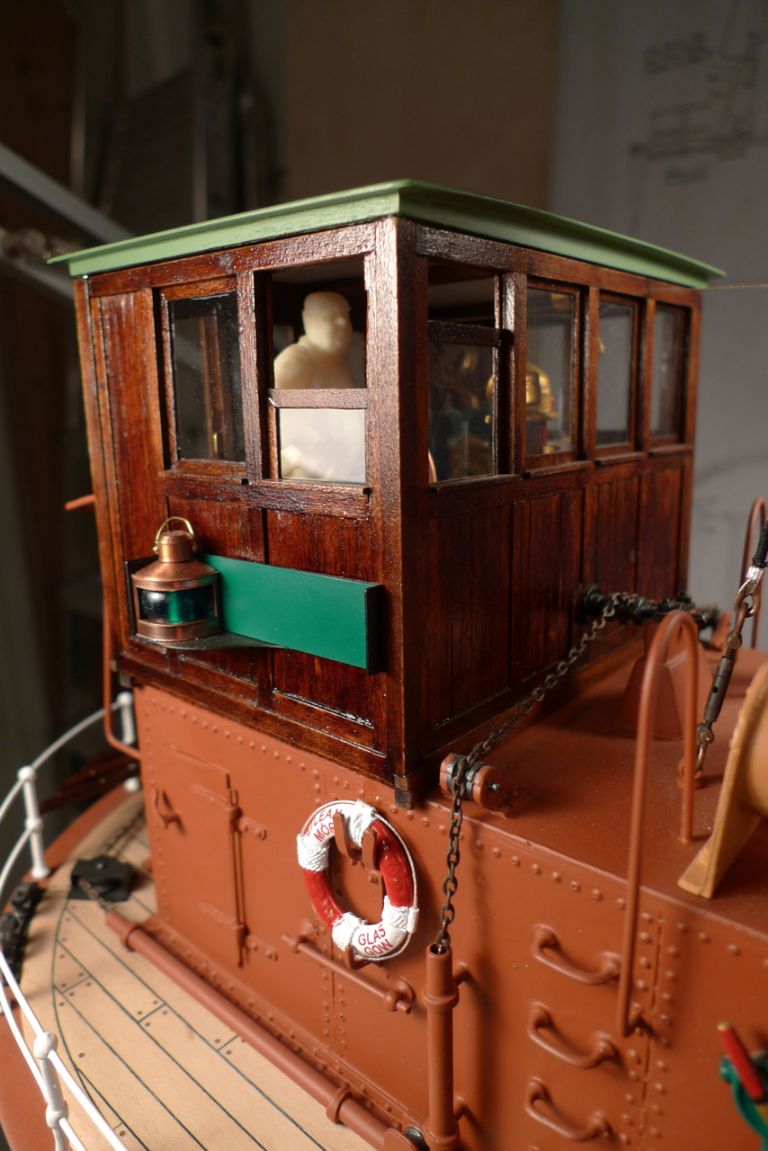
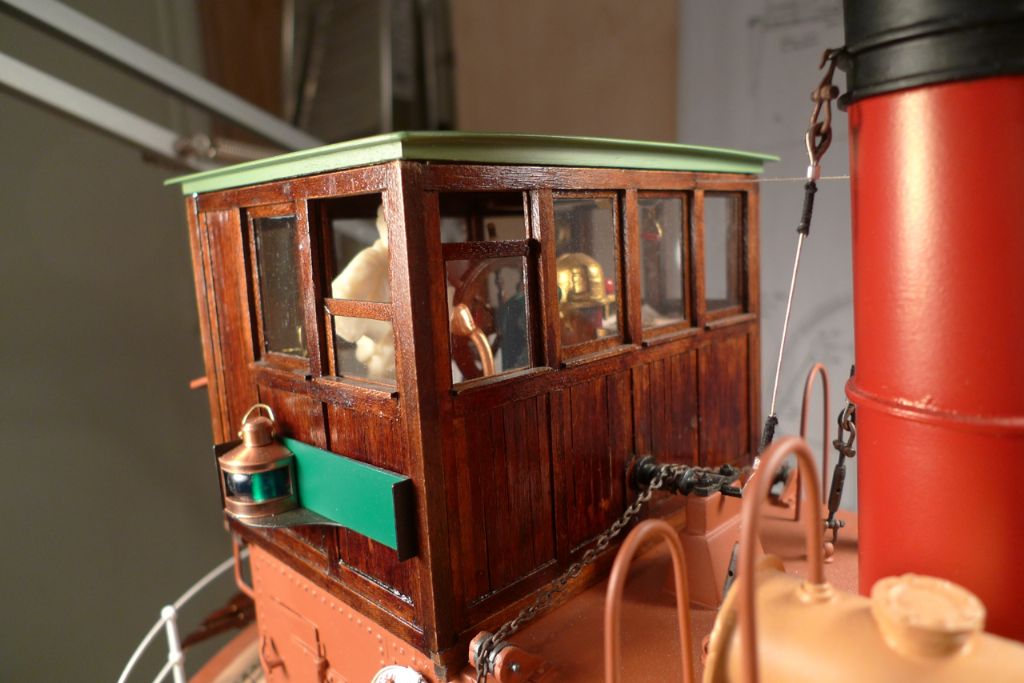
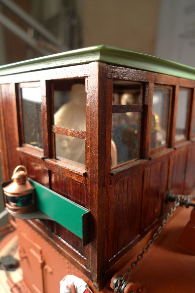
Two windows, at the forward starbord corner, were set partially open …
… to create a bit more varied forms ….
…
Although the real glass panes will of course be rather vulnerable to damage …
… I nevertheless hope they won't break so often …
… as to negate the positive effect of the to my mind superior sheen and transparency …
… offered by real glass.
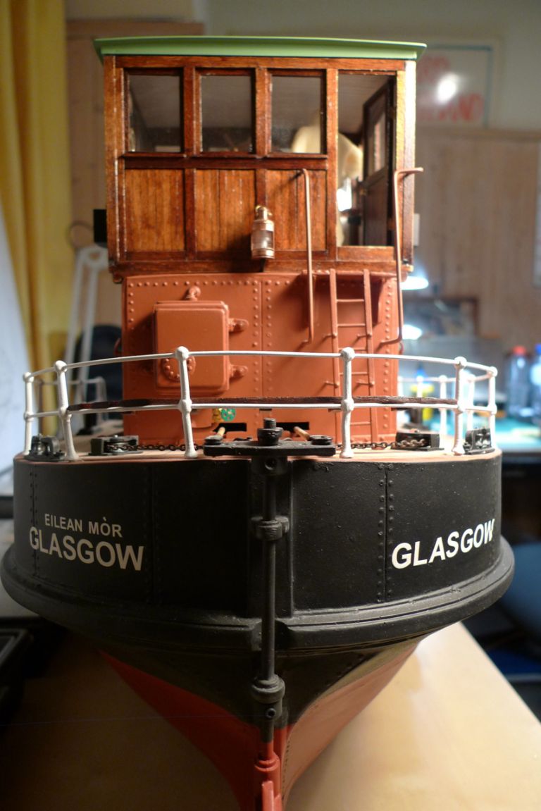
In any case, with this installation of the windows …
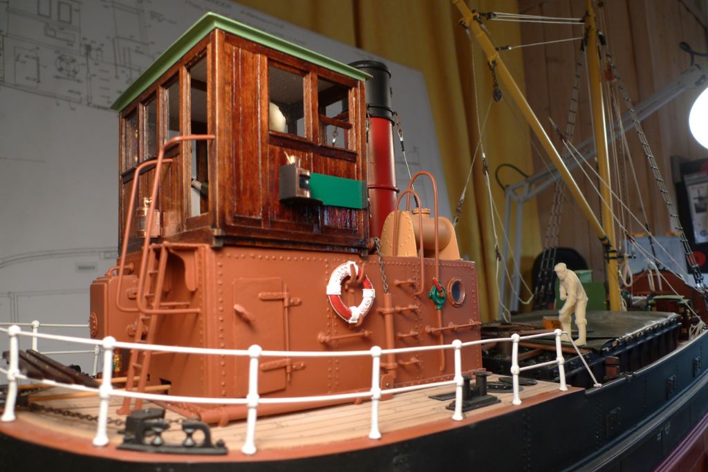
… the wheelhouse is, essentially, finished!

To be continued …
/Mattias
-
AuthorPosts
- Please log in to reply to this topic. Registering is free and easy using the links on the menu at the top of this page.
Code of conduct | Forum Help/FAQs
Latest Replies
Home › Forums › Building Kits › Topics
-
- Topic
- Voices
- Posts
- Last Post
-
-
4D Modelshop
Started by:
Keith Long in: Scratch build
- 6
- 8
-
31 minutes ago
 John W E
-
Fairey Huntsman 31
1
2
…
5
6
Started by:
 Chris Fellows
in: Build Blogs
- 14
- 139
-
15 hours, 34 minutes ago
 Chris Fellows
-
Fairey Faun
1
2
3
Started by:
 Chris Fellows
in: Build Blogs
- 7
- 58
-
15 hours, 56 minutes ago
 Chris Fellows
-
Vic Smeed’s Silver Mist
1
2
…
32
33
Started by:
Bob Abell 2 in: Scratch build
- 4
- 822
-
16 hours, 34 minutes ago
 Tony Hadley
-
Fairey Huntsman 28
1
2
…
7
8
Started by:
 Chris Fellows
in: Build Blogs
- 1
- 195
-
18 hours, 4 minutes ago
 Chris Fellows
-
Eezebilt RAF Fire Boat
Started by:
Tim Cooper in: Build Blogs
- 2
- 3
-
18 hours, 39 minutes ago
 Dave Reed
-
Feathered Friends
Started by:
 Chris Fellows
in: Soapbox
- 3
- 7
-
21 hours, 46 minutes ago
 Chris Fellows
-
John Cobb’s Crusader
1
2
…
7
8
Started by:
 Paul T
in: Scratch build
- 1
- 192
-
1 day, 18 hours ago
 John W E
-
Complex Automata
Started by:
 Colin Bishop
in: Soapbox
- 1
- 1
-
2 days, 20 hours ago
 Colin Bishop
-
RAF Fireboat ID
Started by:
 Dave Reed
in: Collectors’ corner
- 8
- 24
-
3 days, 22 hours ago
Tim Cooper
-
TID steam tug 42″ – PN Thomas drawing enlarged
1
2
Started by:
 Ray Wood 3
in: Scratch build
- 8
- 33
-
4 days, 15 hours ago
 Richard Simpson
-
Lady of Skye (puffer)
1
2
Started by:
 mick east
in: Build Blogs
- 9
- 43
-
5 days, 1 hour ago
 Richard Simpson
-
Building a hull.
Started by:
 mick east
in: Scratch build
- 7
- 10
-
1 week ago
 Ray Wood 3
-
Todays Boating
1
2
…
210
211
Started by:
 ashley needham
in: All things floating
- 84
- 5,252
-
1 week ago
 Colin Bishop
-
Sea Rover Restoration
Started by:
harry smith 1 in: Collectors’ corner
- 4
- 10
-
1 week ago
 Richard Simpson
-
WORKSHOP LIGHTING
Started by:
 John W E
in: All things floating
- 9
- 18
-
1 week, 1 day ago
 Colin Bishop
-
Mayhem Website Down
Started by:
 Colin Bishop
in: All things floating
- 4
- 10
-
1 week, 4 days ago
 Colin Bishop
-
MAGGIE M trawler
Started by:
 sammyk
in: Buy/Sell or Trade
- 2
- 3
-
1 week, 4 days ago
 sammyk
-
meter
Started by:
 Alasdair Allan
in: All things floating
- 5
- 16
-
1 week, 6 days ago
 Chris Fellows
-
River Queen 2”- 1’.
Started by:
Richard B in: Steam powered models
- 5
- 7
-
2 weeks ago
Richard B
-
Deluxe Superphatic Glue.
Started by:
 Colin Bishop
in: All things floating
- 4
- 12
-
2 weeks, 1 day ago
 Chris Fellows
-
How to add photos to your posts
Started by:
 Colin Bishop
in: Adding Images to Forum Posts
- 3
- 16
-
2 weeks, 1 day ago
Len Morris 2
-
Cataract
Started by:
Bob Wilson in: Soapbox
- 2
- 4
-
2 weeks, 1 day ago
 Colin Bishop
-
The mighty tug Wattle
1
2
3
Started by:
 mick east
in: Build Blogs
- 10
- 61
-
2 weeks, 1 day ago
 Richard Simpson
-
Clyde Puffer Glenaray
1
2
3
Started by:
 Alasdair Allan
in: Build Blogs
- 6
- 57
-
2 weeks, 4 days ago
 Alasdair Allan
-
4D Modelshop
-


