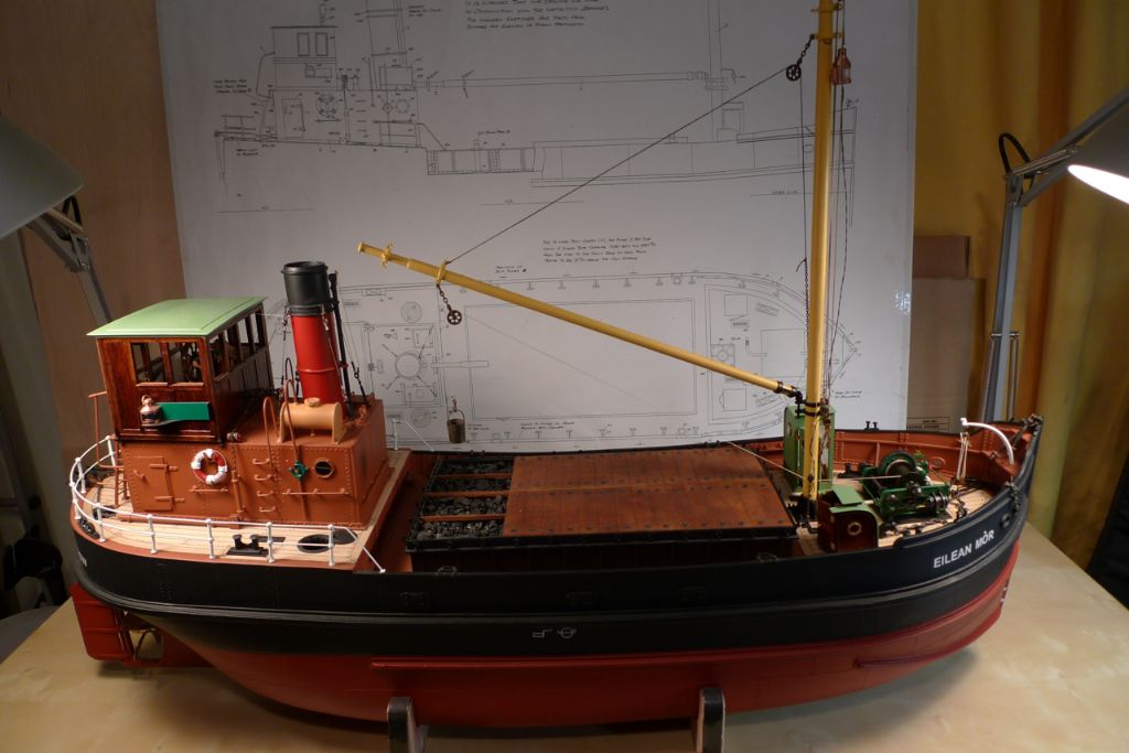
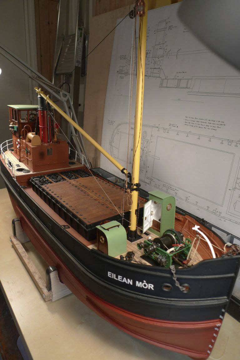
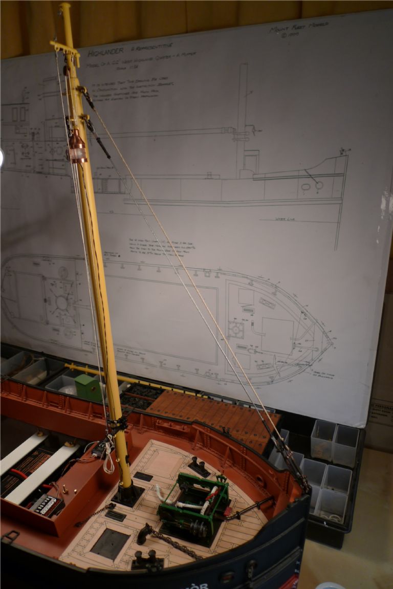
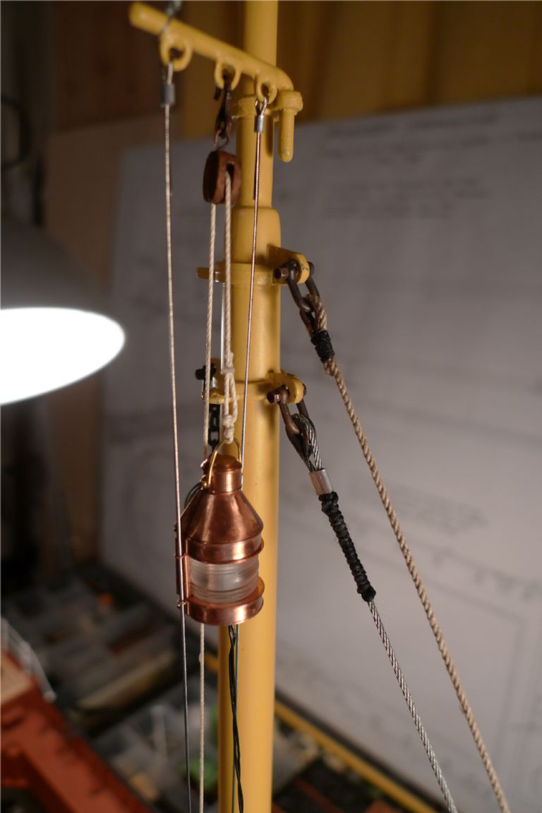
The world's leading magazine for all model boating interests
Eilean Mor
Eilean Mor
Home › Forums › Building Kits › Eilean Mor
- This topic is empty.
-
AuthorPosts
-
8 December 2014 at 08:42 #54178
Banjoman
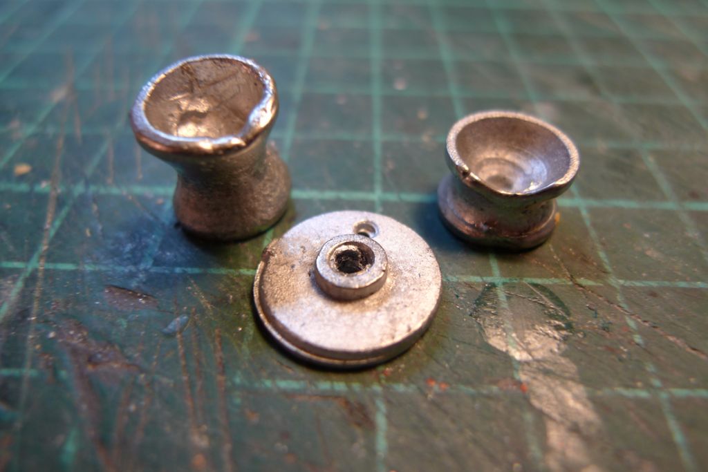
Participant@banjomanMost of the winch castings were fine, just needing some minor cleaning up, and several were superbly cast; however, some others were miscast to the point of being almost unusable as can be seen from the below photo of some of the drum heads and a flywheel. Again, I turned to Mountfleet Models, and once more they came through the customer service test with flying colours, sending me replacement parts within the week!

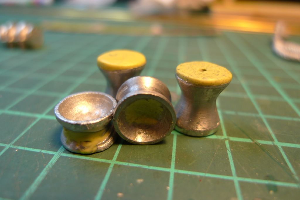
The drum heads still needed a bit of fixing, to really look symmetrical and complete, so some Milliput was added where needed …
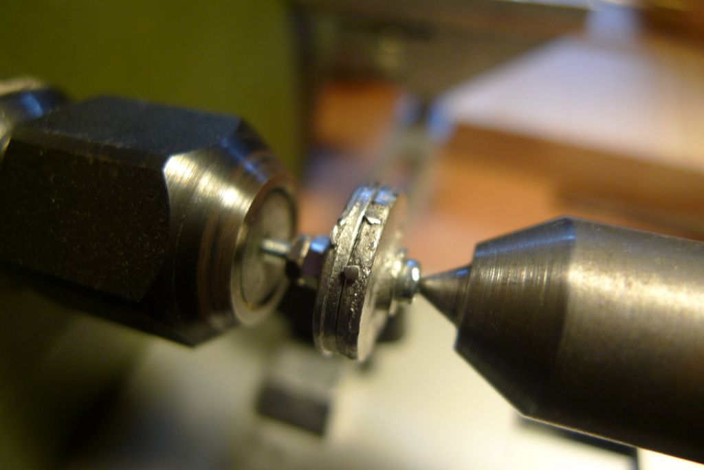
… while the two replacement flywheels were set up on a screw in the lathe …
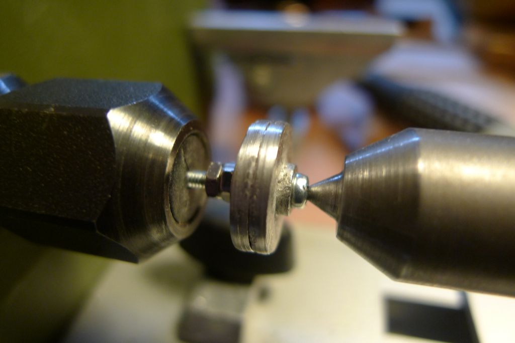
… and turned against a piece of wet and dry paper until equally sized and sufficiently smooth-edged.
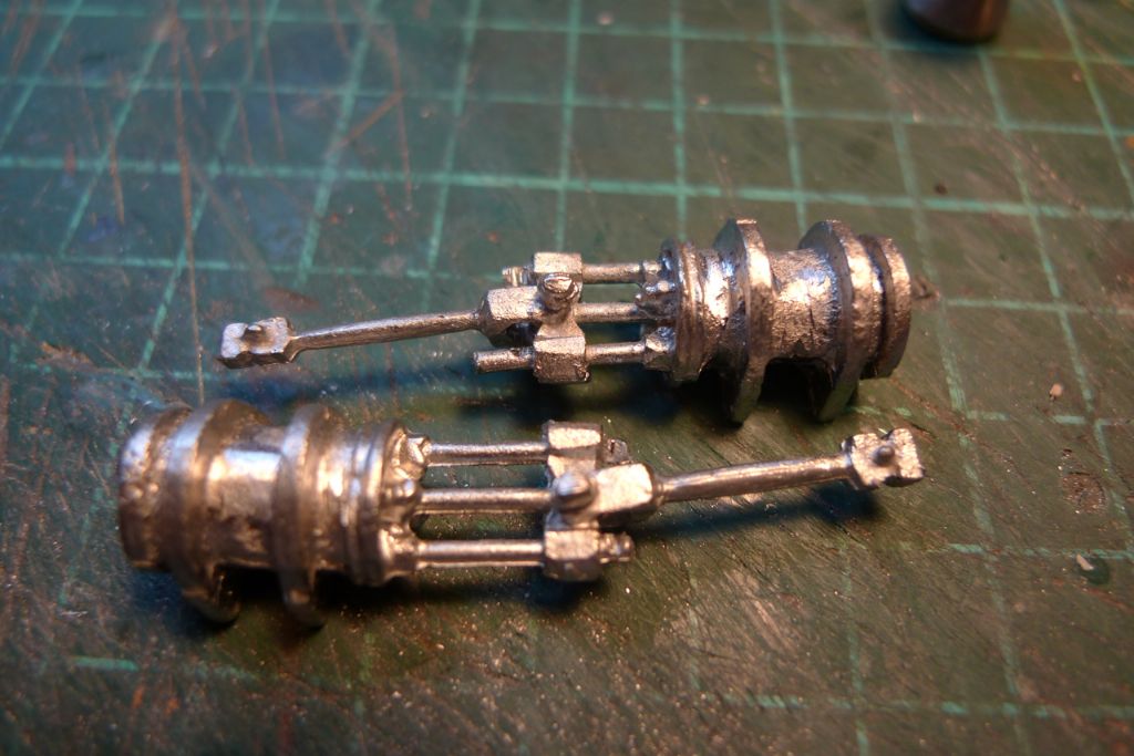
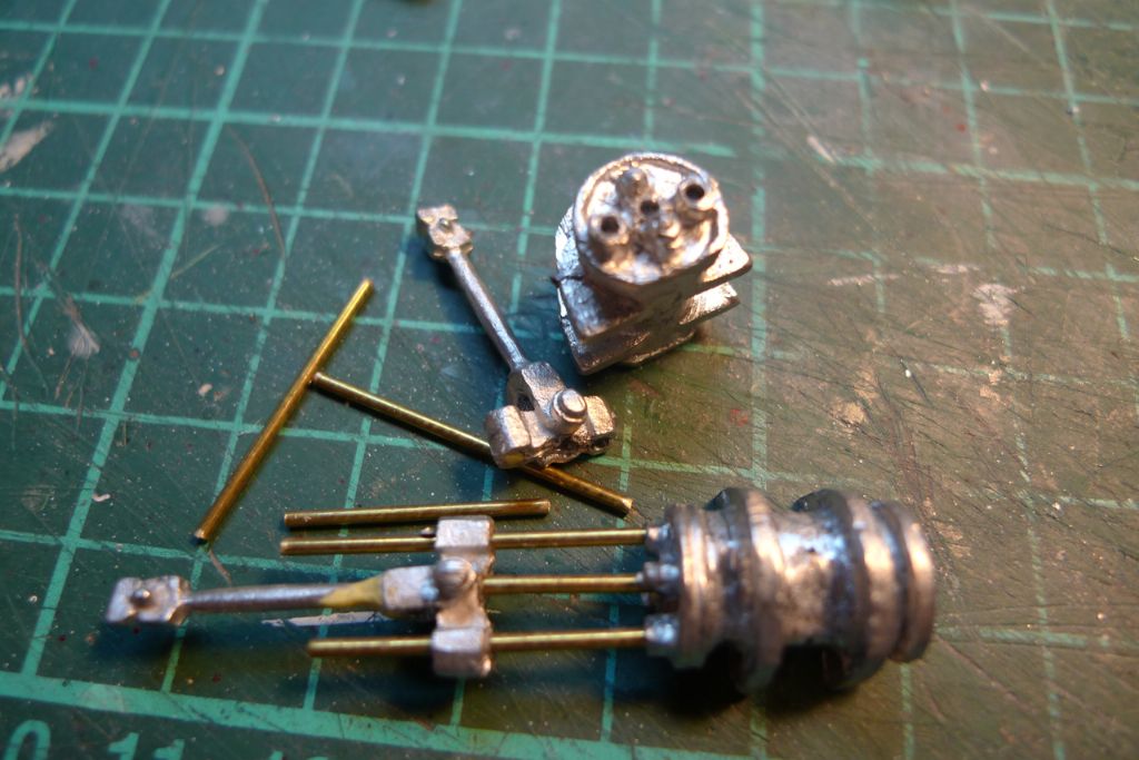
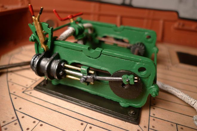
The steam cylinder and connecting rod assemblies were on the whole nicely cast, although I was not really happy with the slide and piston rods.
I therefore decided to cut these off and to replace them with some metal rod, in the photo some 1.2 mm brassrod. In the end I used this for the slide rods, but for the piston rods went with some cut off pieces of 1.8 mm steel nail instead. The cylinder heads and connecting rod slides were drilled to take the replacement rods, while one of the connecting rods that was weakly cast had to be repaired with a drilled-in insert of 0.5 mm brass rod and some Milliput where it broke off during handling. The unseemly Milliput bulge seen here was of course sanded down at a later stage.
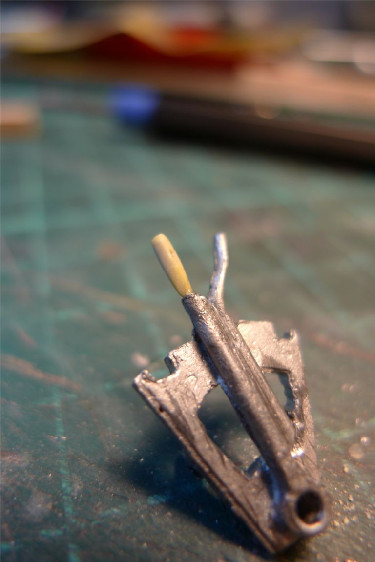
The reversing gear lever handle was not cast sufficiently well to merit replacing when it, too, broke off, and a new one was instead made up from scratch using a thin brass rod insert covered with Milliput.
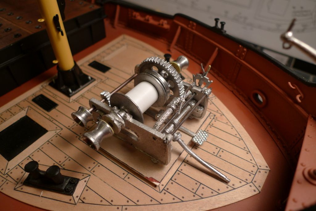
At the end of the above process, the dryfitted result looked like this. As can be seen from the photo, the drum heads and the brake disc braking surface were also polished (using the lathe and some wet-and-dry paper).
To be continued …
/Mattias
8 December 2014 at 08:48 #54179Bob Abell 2
Participant@bobabell2Excellent work, Banjo!
Your workmanship is of the finest quality and will be a "Sight for sore eyes" when finished and on display!
Hope you understand the local dialect phrase?………(It`s a compliment)
Bob
8 December 2014 at 15:20 #54193Banjoman
Participant@banjomanI am indeed familiar, Bob, with the colloquial phrase in question, and thank you most sincerely for your kind compliment!

As mentioned in a previous posting, I'd decided to use the plywood base that came with the kit only as an assembly jig, and I thus set about making up a new base plate; again from plywood, but from two pieces, one slightly larger than the other. This was mainly to add a millimetre or so of height to the base, but also to create a visually slightly more interesting form by making the base stepped at the edges.
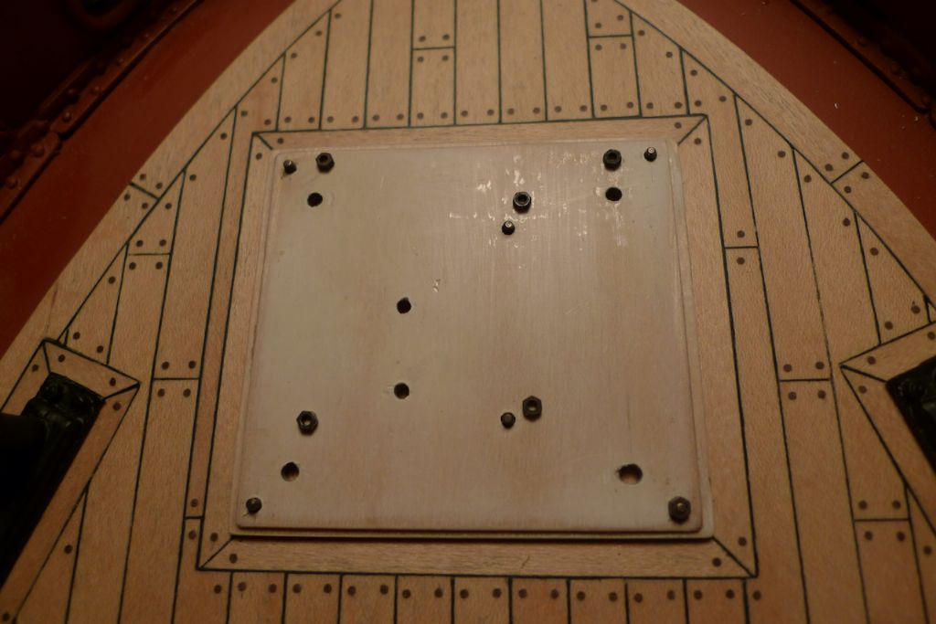
The spacings for the winch side plate and brake pedal tabs were transferred from the original base and drilled, after which six more holes were added — one at each corner and two (more or less) in the middle — and corresponding holes drilled through the deck, so that the whole base could be bolted down using M1.6 nuts and bolts, again from the RB Model assortment.
The whole thing was then dryfitted to check that it would go together as intended …
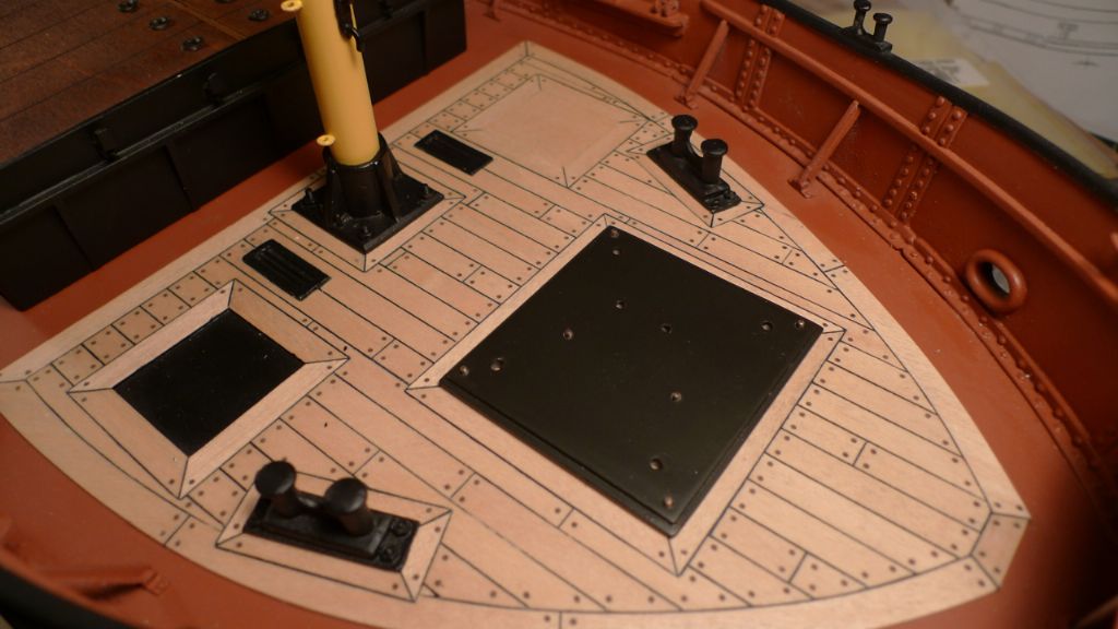
… after which the base was painted in an off-black colour of my own admixture; it seemed to me that a plain black might look a tad too, well … black … here, so I mixed 2 parts 62.018 (Sepia) with 1 part 62.019 (Grey) and 1 part 62.020 (black). The result is still mainly black (that Vallejo Premium RC Black paint has a pigment that is one of the strongest and best covering I've ever come across!), but shifting towards a darkish brownish sort of oily hue, that I think looks rather better on such a large piece as this base plate.
At this stage I also had a long think about the reversing gear. Out of the box, the kit does not provide any sort of linkage between the reversing gear axle and the motive parts of the winch, and for my part I had no idea how the reversing gear on a steam deck winch of this kind would have been connected up or functioned in real life.
After some fairly obsessive research on the Internet, where most of the results thrown up were of little or no use (why do people only ever take photos of technical things from so far away?!?), I finally came across a 1944 publication called the United States Maritime Service Training Manual, Engineering Branch Training (essentially Marine Engineering for Dummies, intended to "help turn farmers into seamen" for the war effort)´. On p. 66 (**LINK**) this very interesting read explains the workings of a differential valve for reversing purposes, including the phrase "[d]ifferential valves are also used to reverse steering engines and winches […]"!
Right! From what I understood, such a differential valve would be part of or attached to the steam chest; in other words the axle needed to be connected to the steam chests. Not in a working way, of course, but at least in such a way that it would look like it might have been one way of actuating valves built in to the steam chests.
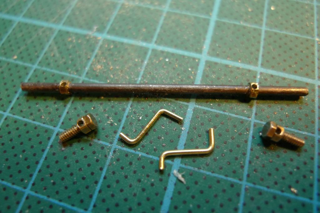
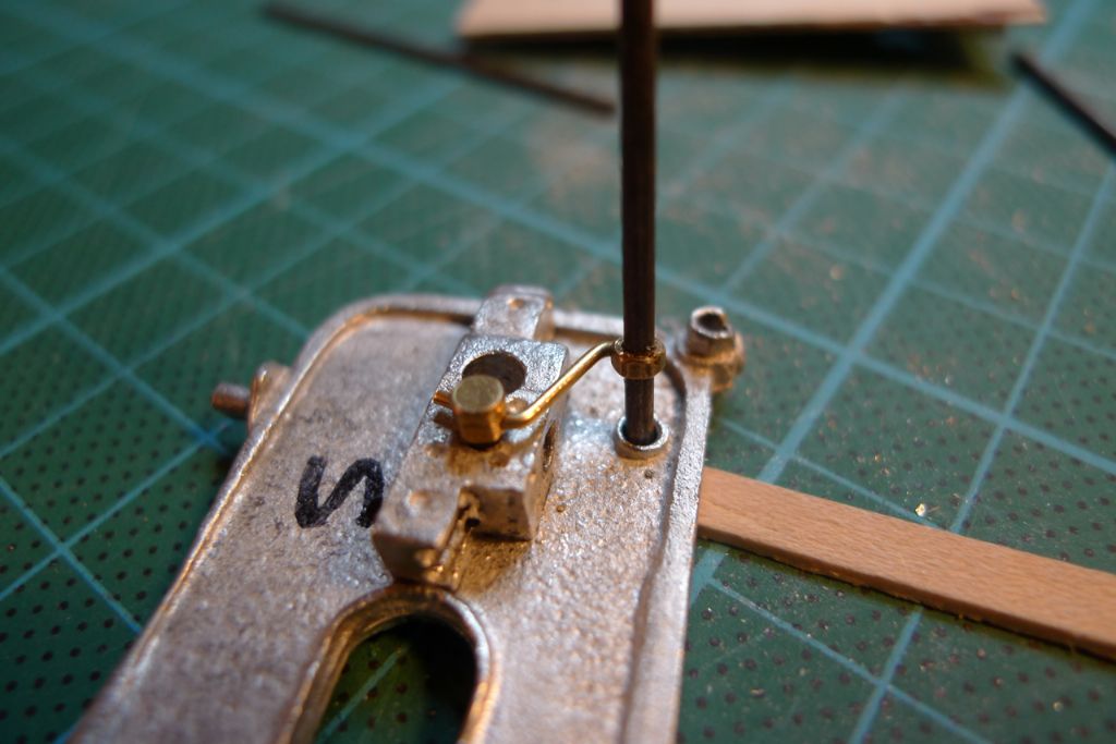
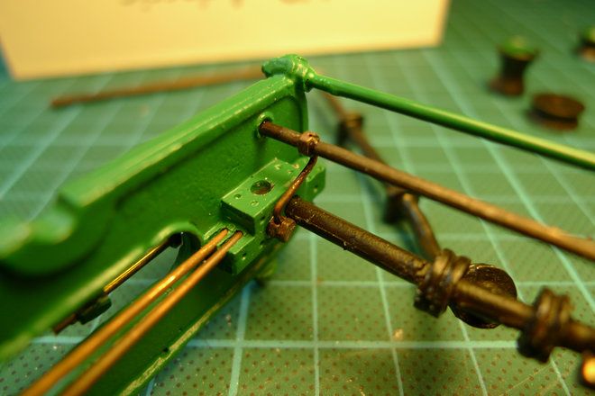
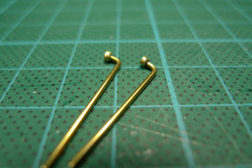
I therefore drilled 0.5 mm holes in two M1.4 nuts, slid them onto and CA-glued them in place on the axle. Two more M1.4 nuts and bolts were similarly prepared, and two small connecting shafts bent out of 0.5 mm brass rod.
The nut-and-bolt parts were then set into the steam chests (which had by now been glued onto the inner faces of the winch side plates), and the connecting shaft set into the 0.5 mm holes drilled into the nuts.
To really transfer a rotary motion from the axle to the valve actuators, the connector should of course have been hinged at both ends, rather than being just a solid, bent piece, but I though that that would be taking detailling a step too far, not least given that these contraptions would hardly even be visible with the whinch assembled, as they are largely hidden by the steam intake pipe … Still, I very much enjoyed the research and what it added to my knowledge of how things like these would or at least might have worked.

To be continued …
/Mattias
Edited By Banjoman on 08/12/2014 15:23:58
Edited By Banjoman on 08/12/2014 15:25:14
9 December 2014 at 08:38 #54211Banjoman
Participant@banjomanMy research on steam deck winches mentioned above also threw up the nugget of information that condensation in the cylinders and steam chests is even more likely than usual on this type of engine, as they (a) often do not run continuously, but in starts and stops, and (b) sit fully exposed to the environment, which often leads to significant differences in temperature and thus a rapid cooling of the steam as soon as the winch is halted.
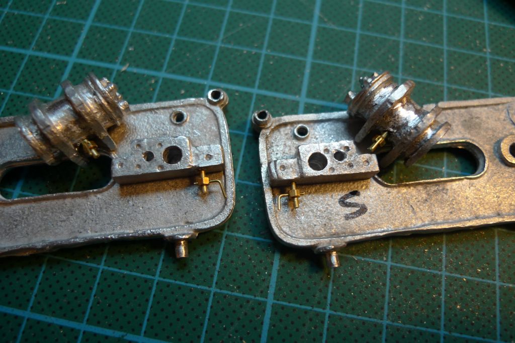
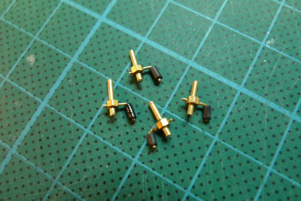
To avoid corrosion, cylinders and steam chests must thus be regularly drained, and I therefore decided to also add drain cocks …
… that I made up from some brass tube onto which was passed a nut, CA-glued in place and drilled through to take a piece of bent brasswire with some shrink tube for a handle.
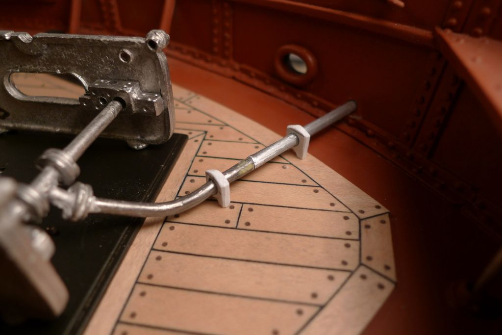
I also prolonged the steam exhaust pipe and drilled through the bulwark for it to pass out of the ship. As the pipe could not quite be made to sit flat on the deck (because I had chosen to drill the hole through the bulwark above the angle reinforcement, i.e. a few mm above deck level) I also added two support pieces made up from styrene strip.
I was now ready to start painting the winch parts …
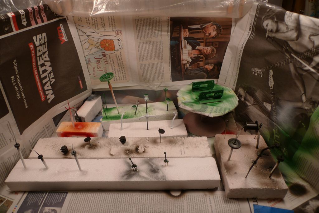
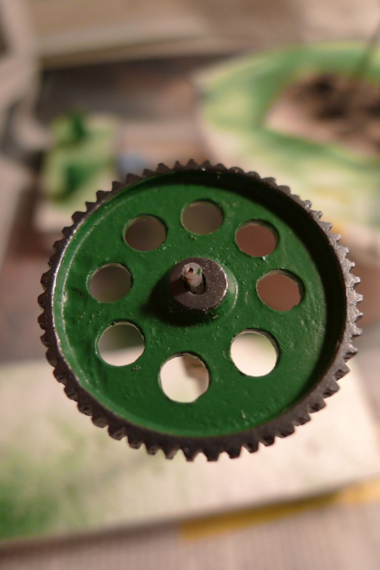
… mainly by airbrush, but with certain details (such as the gun metal-coloured gear teeth, here) done with a regular brush instead. One of the many nice things, by the way, about the Vallejo Premium RC-series of paints is that (with the possible exception of the primer) they work very well both in an airbrush and on a normal brush.
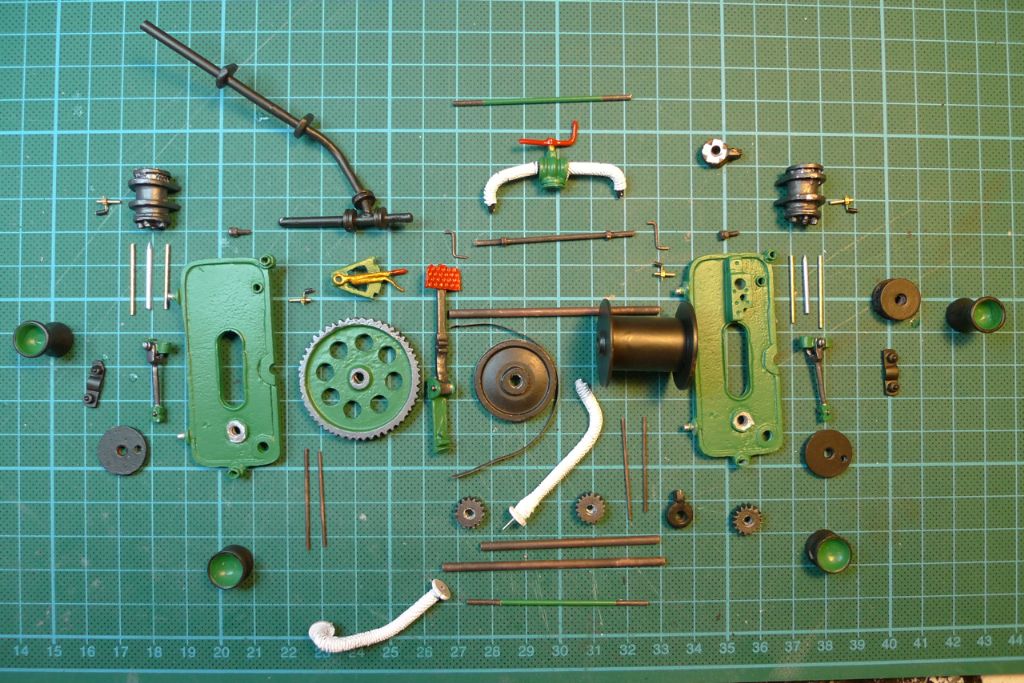
After some further detail painting I ended up with all in all 54 different parts, not counting the base plate.
I then began assembling the winch …
… making sure, of course, that the crankshafts and flywheel were set at a 90 degree angle to each other …
… and connecting up the eccentric rods and the reversing gear axle with the steam chests.
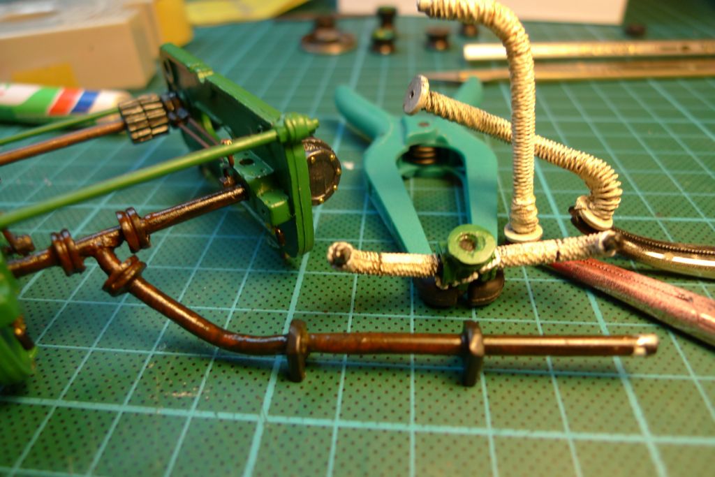
I had made up my mind early on not to weather this model to any extent, but as I felt that in particular the steam intake pipes would look a tad too pristine if they were left snowy white, I decided to carefully add some oil paint washes to them; I also added some similar light discolorations to the steam exhaust pipe …
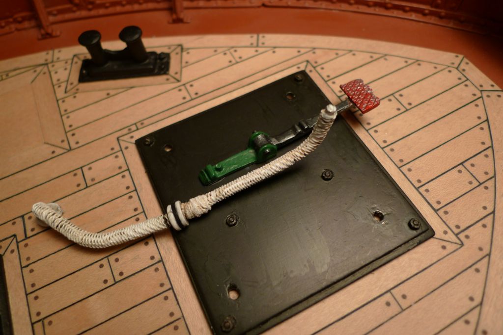
… and finally a worn effect to the brake pedal. A gasket between the two parts of the steam itake pipe was simulated using a thin slice of PVC microphone cable sleeve. The righthandmost part of the steam intake pipe was by the way slightly miscast next to the gasket plate, and before painting I therefore "repaired" the lack of cast lagging there by going around the pipe a few times with some thin rigging thread to make it look like the pipe and/or the lagging had actually been repaired/added on to.
I also drilled the crankshaft heads for and inserted two short pieces of 0.5 mm brass rod to represent the original cast bolt heads that I had removed at an earlier stage.
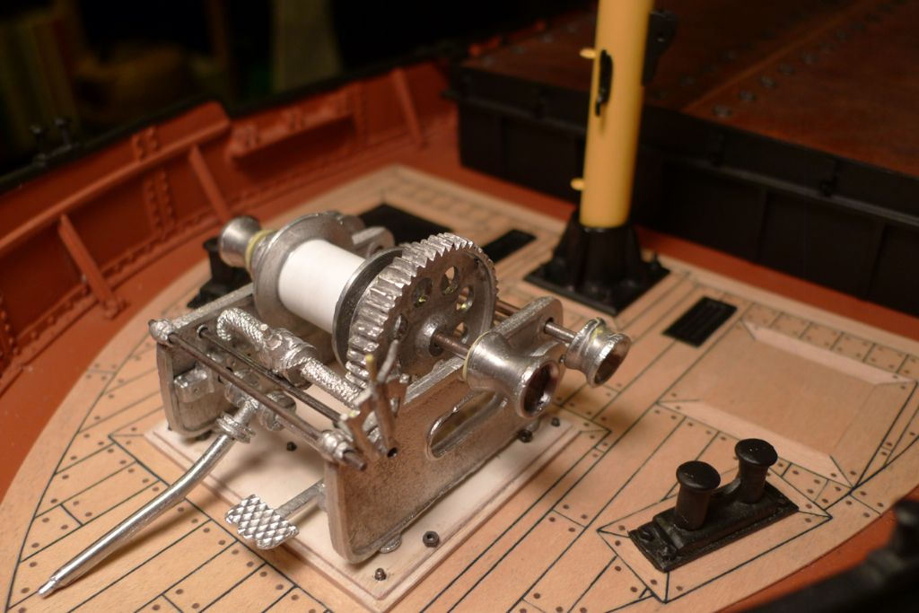
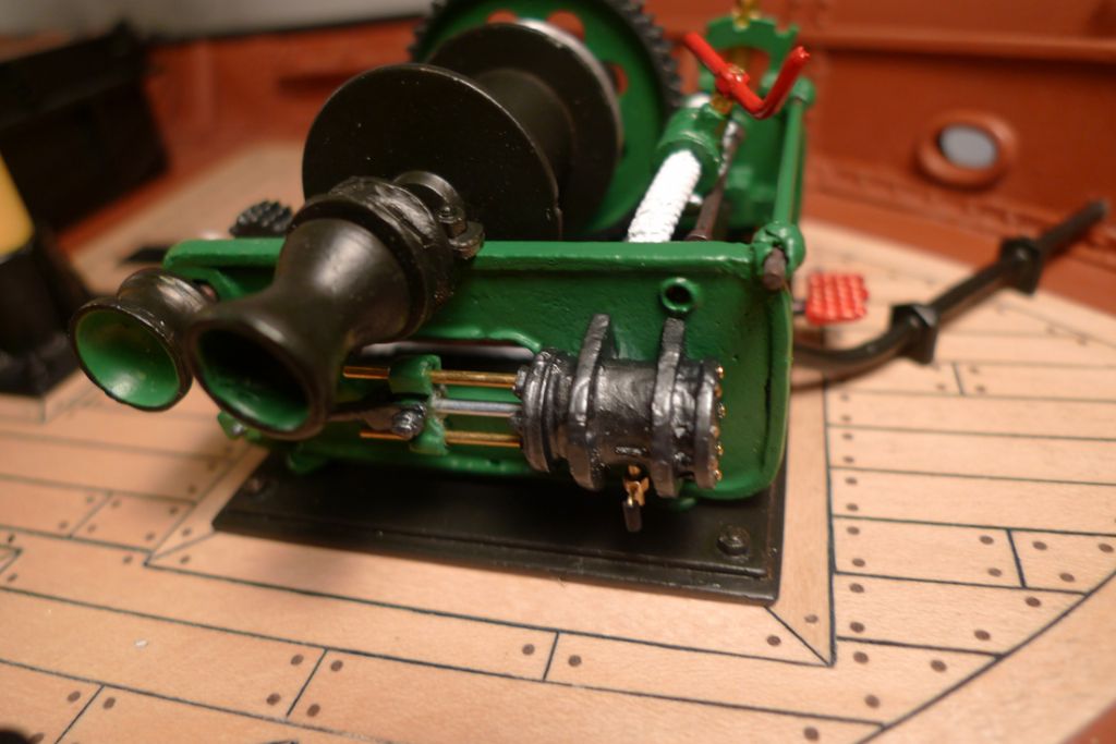
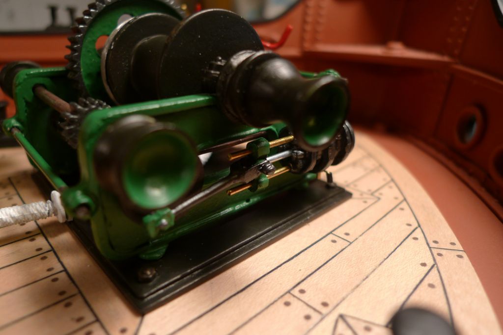
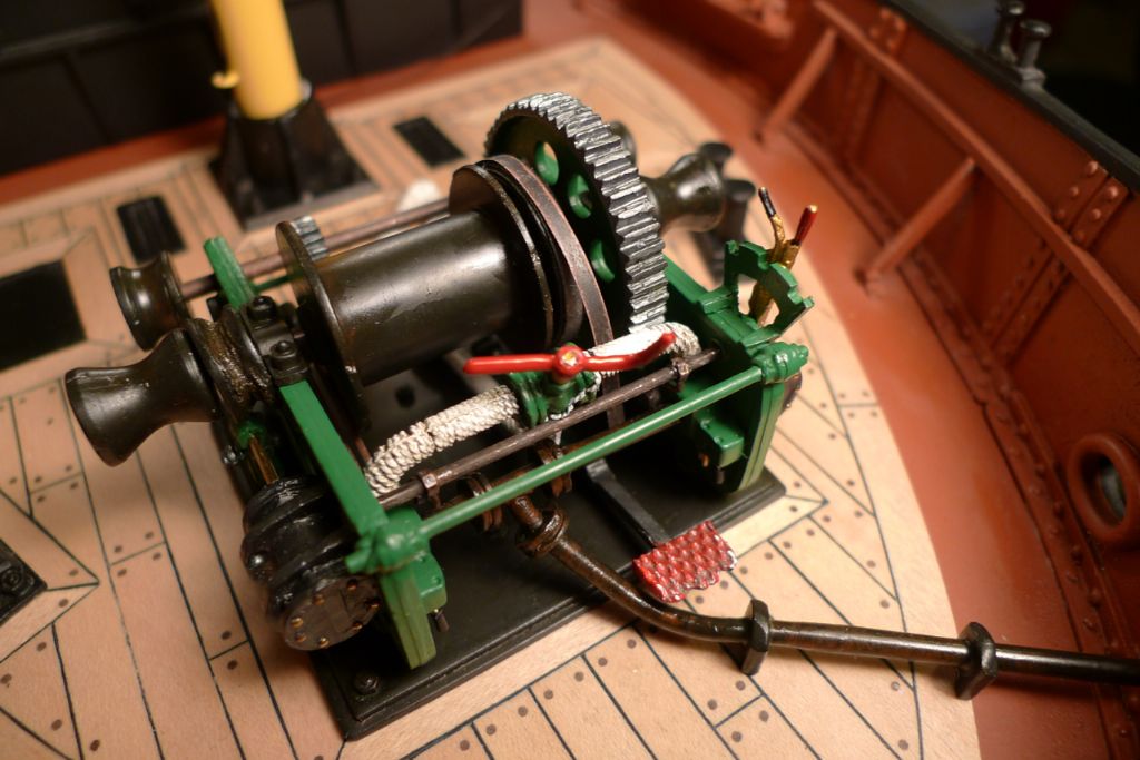
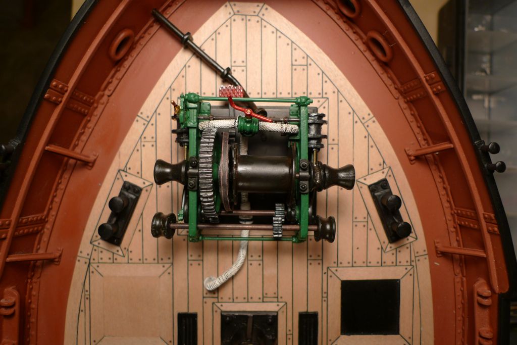
After the addition of some very mild oil paint discoulorings to the main drum, the various drum heads and the gipsy wheel, the winch looked like this. One can also see here that some round headed brass nail heads were likewise added to the end plates of the steam cylinders.
The two "working" axles and the various drum heads were as yet only dryfitted, awaiting the addition of the whip wire at a later stage, but otherwise the winch was now pretty much finished.
To be continued …
/Matt
9 December 2014 at 09:11 #54212Bob Abell 2
Participant@bobabell2Excellence in miniature…..Nice work, Banjo
Bob
10 December 2014 at 09:14 #54230Banjoman
Participant@banjomanThank you very much, Bob!

With the winch done for tye moment, I next turned my eye to the two superstructures on the foredeck, namely the privy and the companionway shelter.
As had been the case for the wheelhouse, the kit came with printed plywood parts for the foredeck superstructures, and again I decided to rather build these myself from scratch. I still cut the kit parts out from the plywood sheet, though, to use as a point of departure when deciding on shapes and measurements for my own designs.
I thus transferred the shapes of the kit parts into the computer, and, after playing around some, came up with a design that would do as a base for both the privy and the shelter.
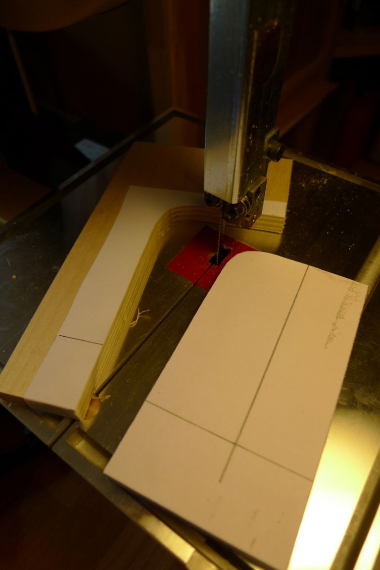
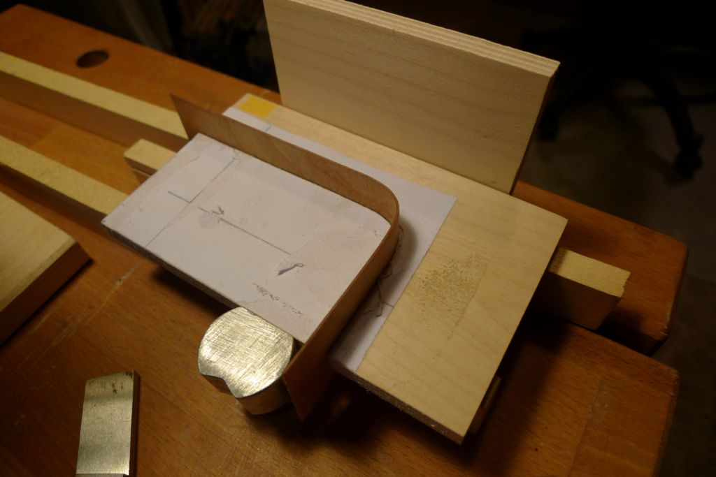
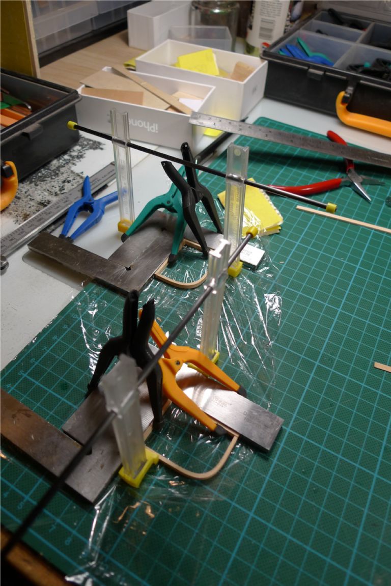
The first problem was to create the curved roof line shape. To this end, I glued a print-out of my design onto some scrap plywood, and carefully cut out the back curve on the bandsaw.
This gave me a former, in which I first tried to bend some 3×2 mm maple strip that had been boiled soft. Given how the wood had been cut, though, the fibres could not really manage the fairly sharp bend, and the wood kept cracking, so this approach had to be abandoned.
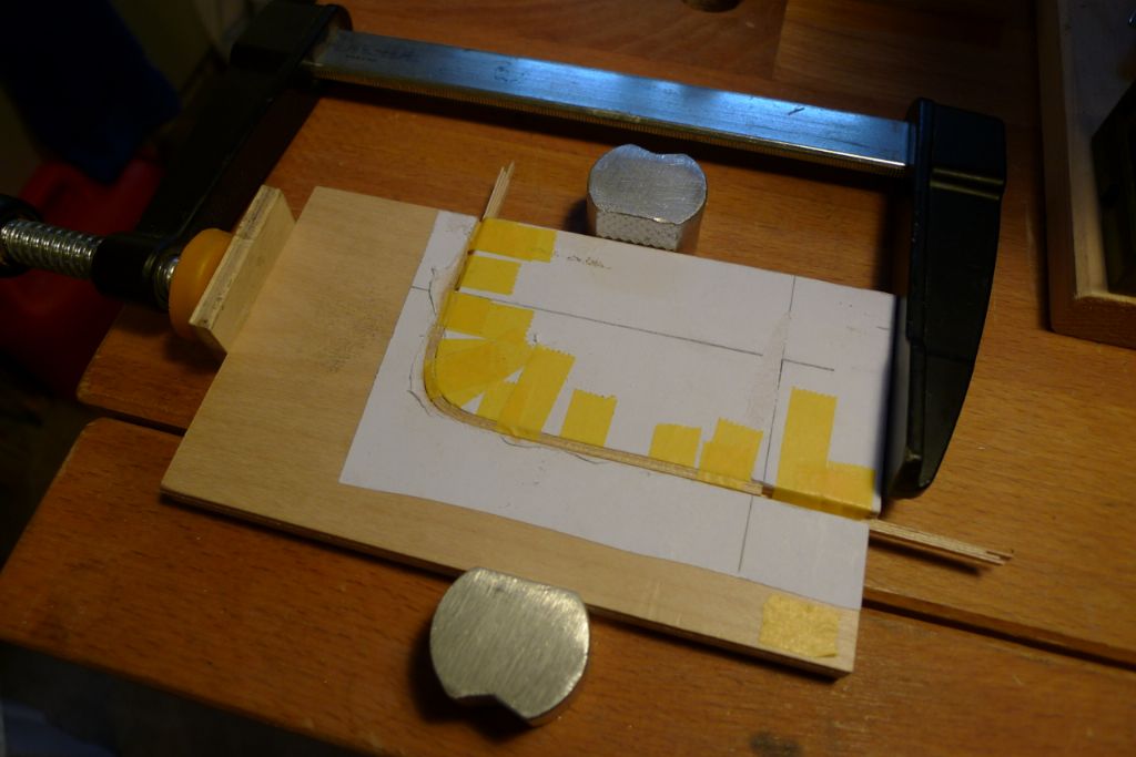
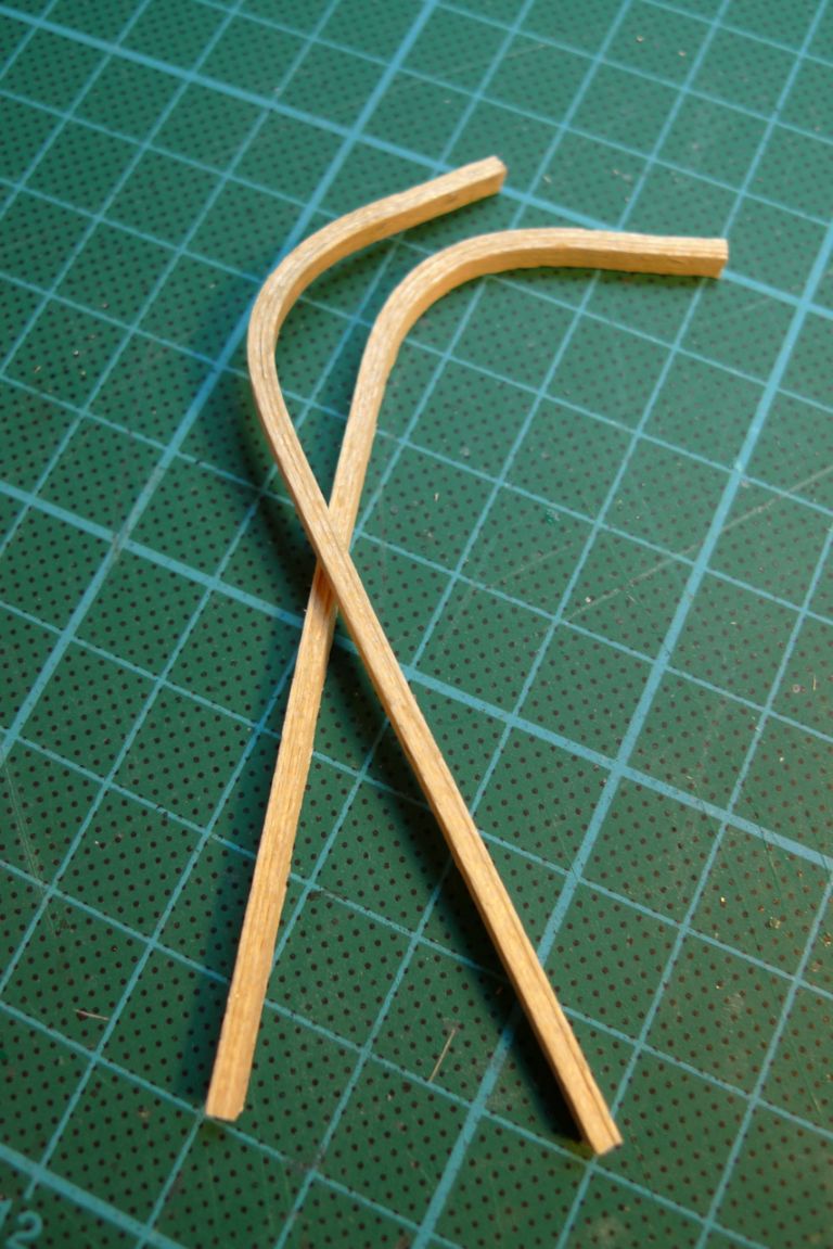
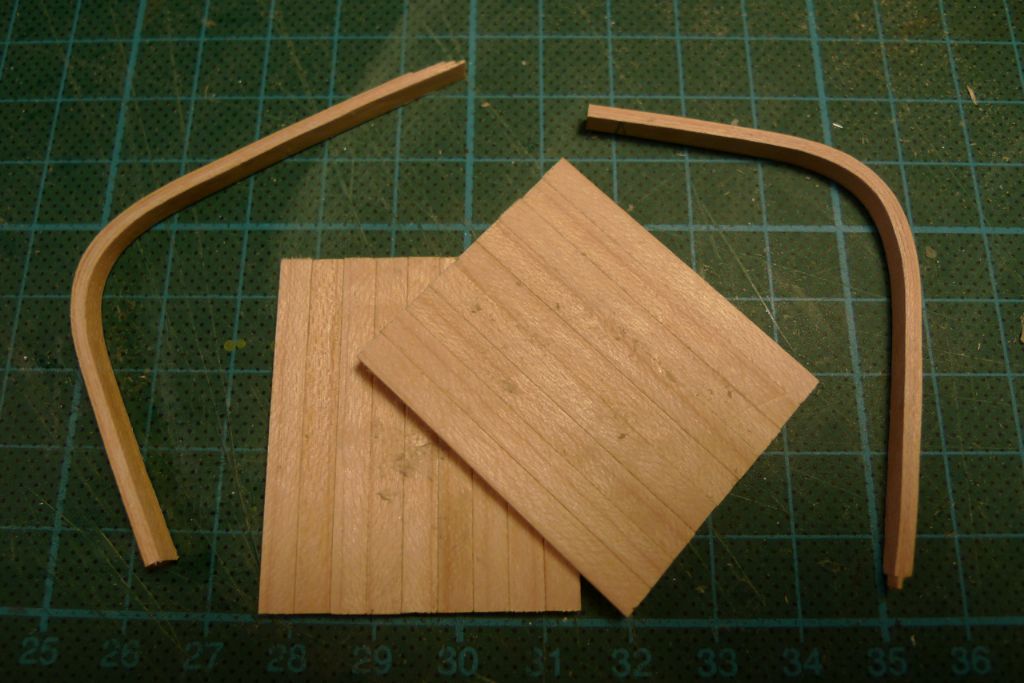
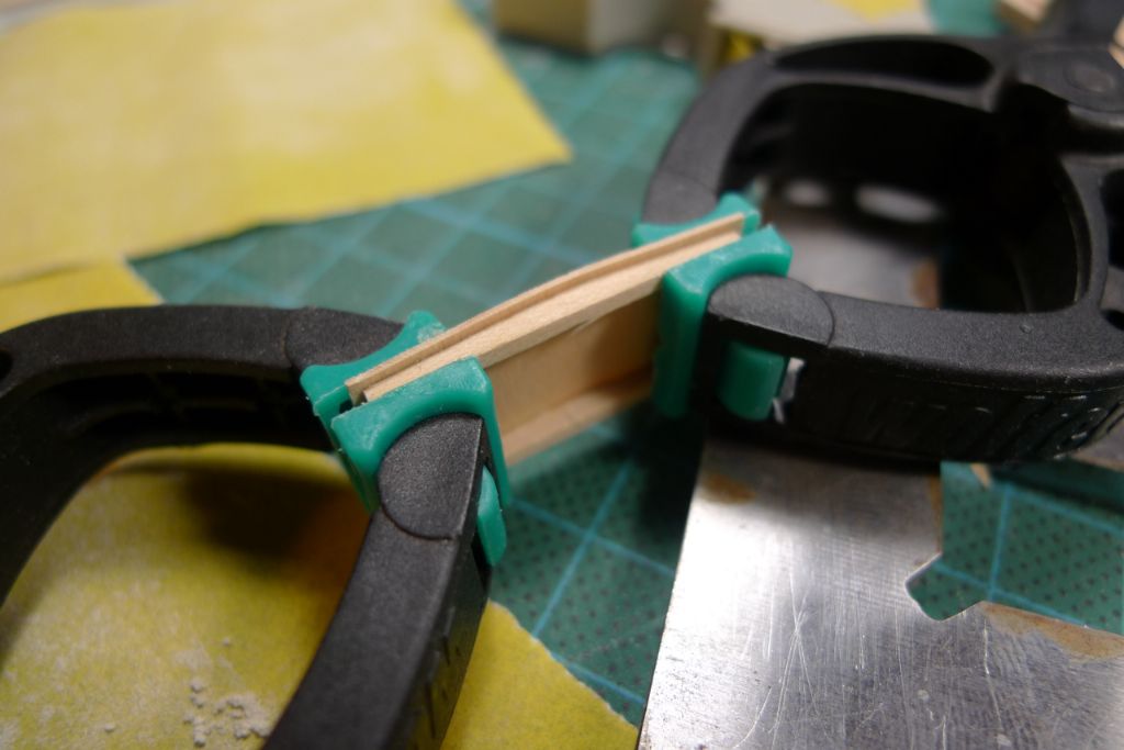
Instead, I hit upon the idea of laminated wood, like one sees on for example an IKEA bent wood armchair (**LINK**), and I therefore glued together fours strips of 3×0.5 mm maple strip with PVA glue and set them to cure in the former.
The result, after trimming to size, was two identical and perfectly form stable back beams for the privy.
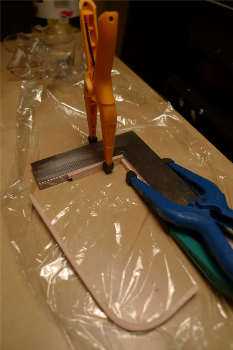
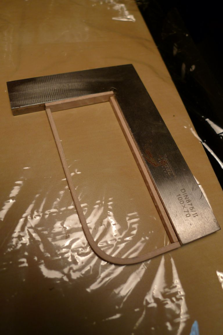
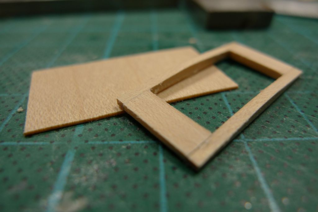
I then cut and glued the bottom and the front upright beams (the kitchen foil is of course there to stop the pieces from also being glued to the table) at right angles …
… attached the back beams …
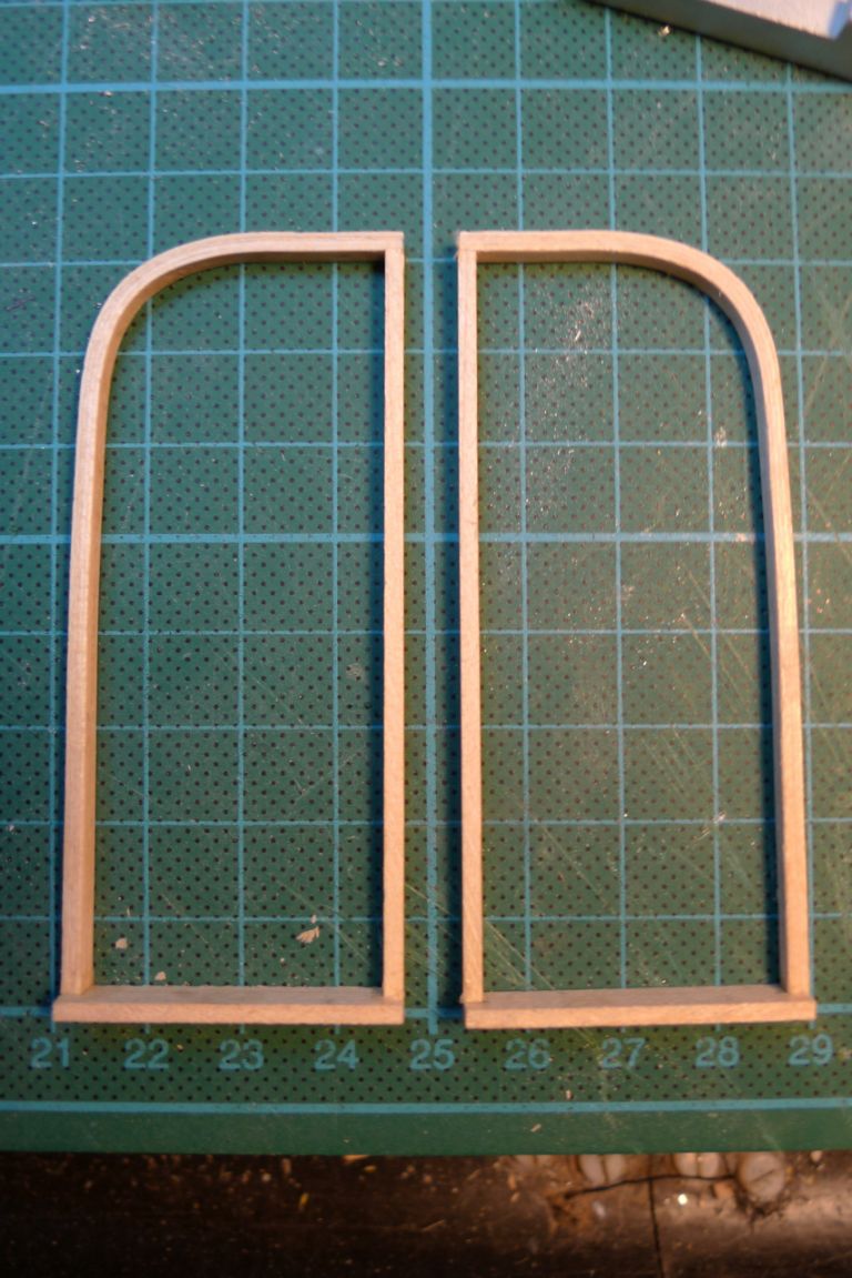
… and hey presto, I had two side frames …
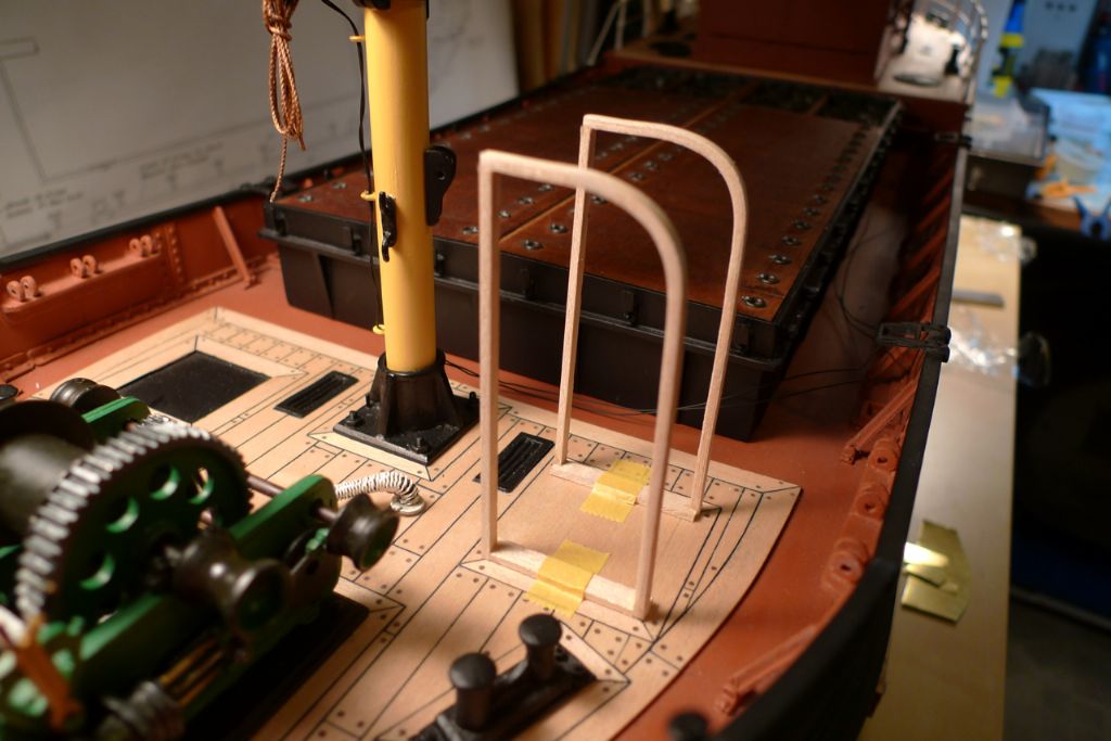
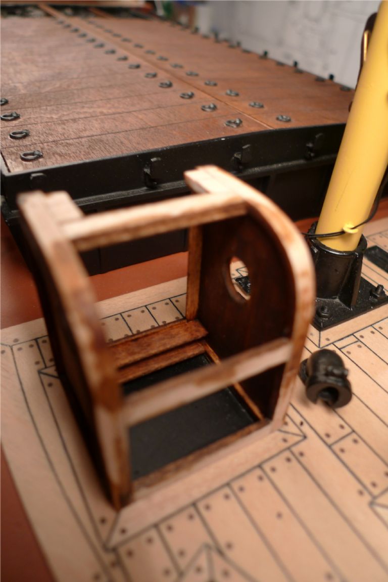
… that looked like this, dryfitted in place.
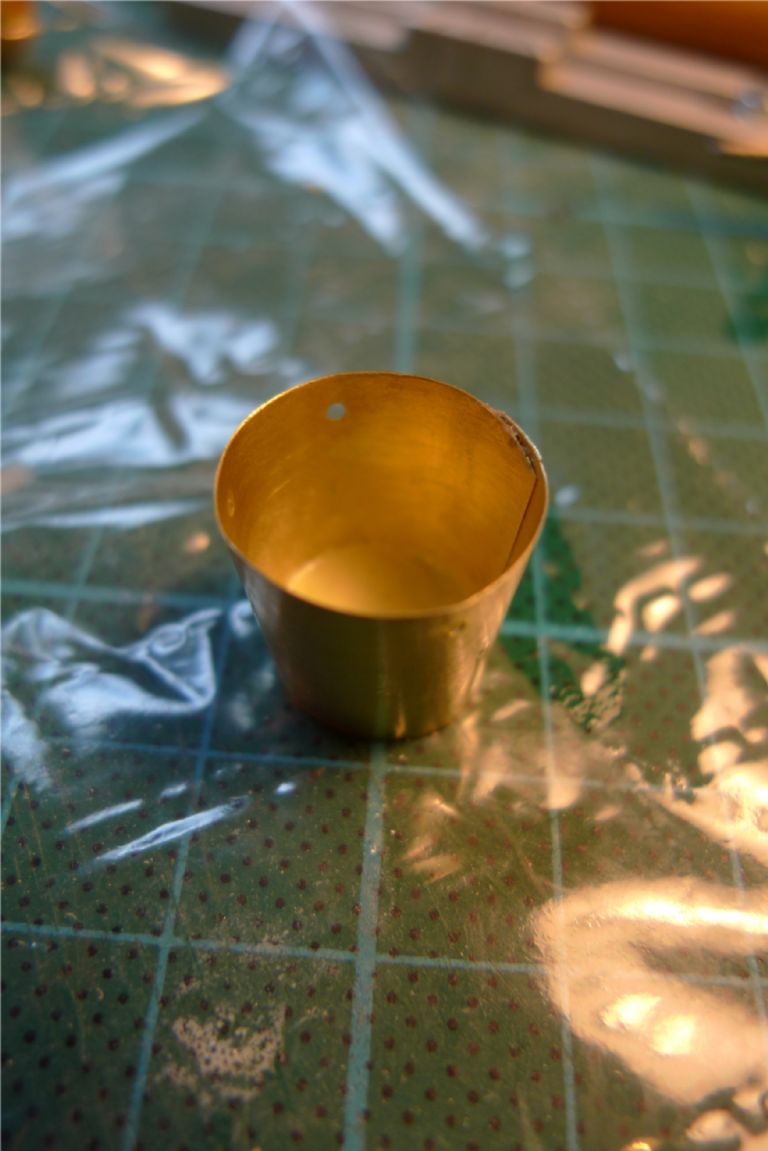
While waiting for the glue to go off during the various construction stages just described, I also made up another brass shim bucket on the bucket former previously discussed, with a bottom made of rolled-out Milliput (as I planned to paint the bucket anyway, to represent enamelling, the difference in material would not matter, and Milliput is of course ideal for such a job: just roll it out to the required thickness, and then use the bucket lower rim as a sort of cookie cutter).
To be continued …
/Mattias
Edited By Banjoman on 10/12/2014 09:17:24
10 December 2014 at 14:34 #54233Banjoman
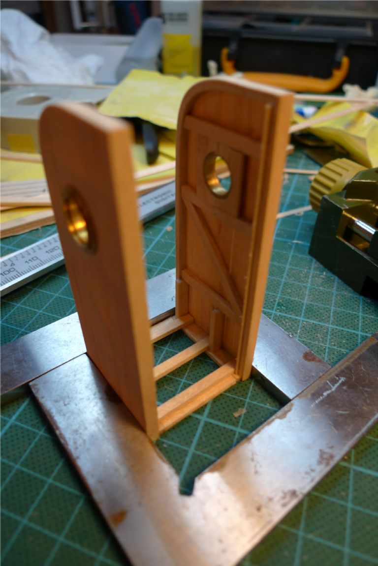
Participant@banjomanThe two side frames were panelled on the outside only; although I wanted the privy to be a reasonably sturdy structure, I also wished for it to have, let's call it a shed-type structure, i.e. one of a frame covered by single (and simple) planking.
Once the glue had set, the excess was trimmed off …
… the two gables given a dry-fit once-over …
… and a full internal framework added, including smaller, triple planked sections in the upper half to take the port hole flanges, and the basis for the seat support structure at the lower back ends.
It was at this stage that I began to realise that I had made a mistake of a sorts when planking the foredeck! I had in fact based the measurements of the privy underframing (and thus the footprint outline of the privy itself) on the measurements on the plan and of the plywood kit parts, without actually checking these for scale realism at that stage.
I subsequently laid out the denk planking based on these original kit measurements, thereby locking myself in to them. However, when I much later began actually building the privy, I did measure a few real-life toilet seats (!) for size, height and depth of placement etc., and came to the inevitable conclusion that if I wanted realistic measurements within the available area at this end of the business, there wouldn't be much space left behind the door for a visitor's knees and feet. Oh, bother.
In the end, though, I decided to give looks, i.e. allowing 3 mm of underframing edge to show all around the privy as originally intended, priority before internal spatial realism.
I also decided to alot more or less the required amount of space to the seat board, to have proper room for both the seat ring on top and the bucket underneath. At a pinch one can always argue that lack of space on the foredeck forced the builder of the privy to be ungenerous in this regard and its users to partially waive their privacy by keeping the door slightly ajar when seated, whereas too short a seat would simply not permit the structure's primary function to be fulfilled. I know, it is a weak argument, but still. You'se pays yer money and you'se takes yer choices.
While working on the above, I also set a soaked plywood roof blank to dry to shape (well, almost; it would still spring back a little when released, but it did help make it more pliant for glueing in place later) in the former.
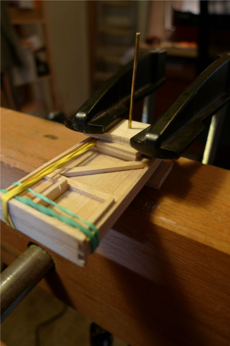
The two gables were then drilled through with a 2 mm drill in the centres of the triple planked areas, as were the requisite number of scrap bits of plywood to set up a drilling sandwich around a length of 2 mm brass rod. This contraption was then clamped down on to the carpenter's bench (on top of one of the bench dog holes, obviously, in order not drill into the bench itself) …
… the brass rod pulled out, and the lined up 2 mm hole used to guide the full size drill (10 mm I think it was) when drilling the final holes. The plywood sandwiching of course served to keep the gable planking from being torn or split when the drill cut through.
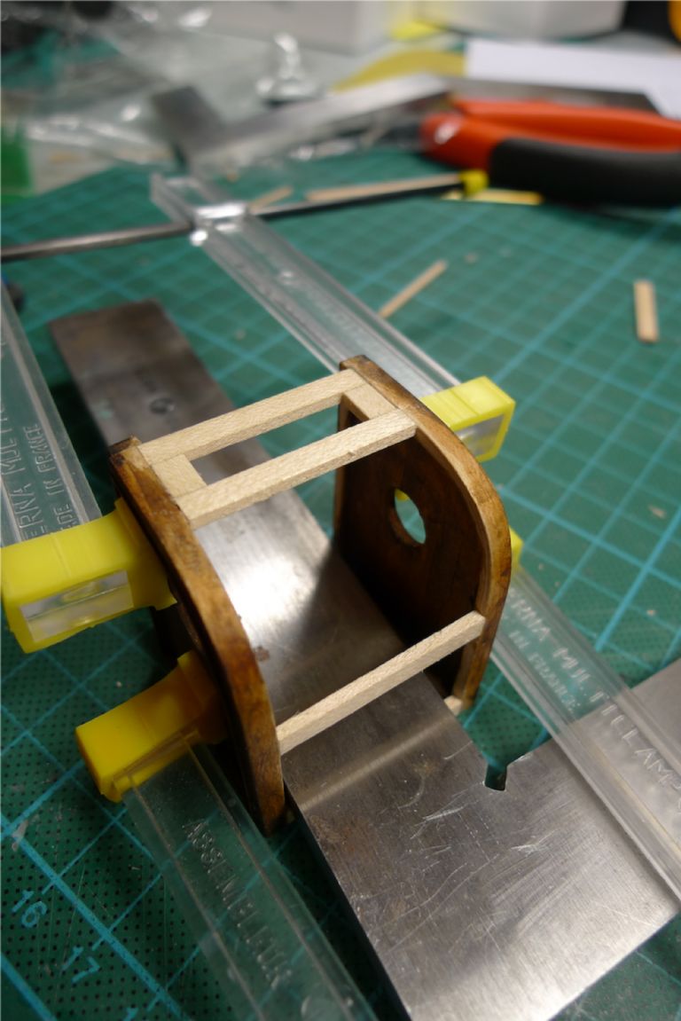
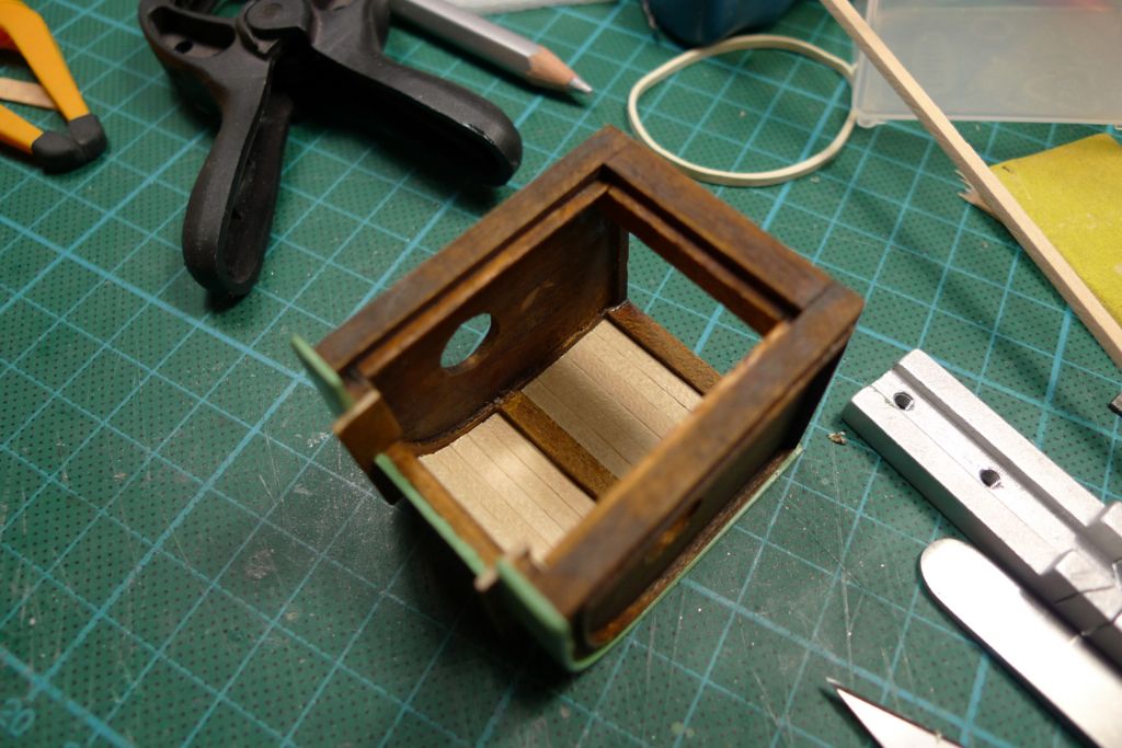
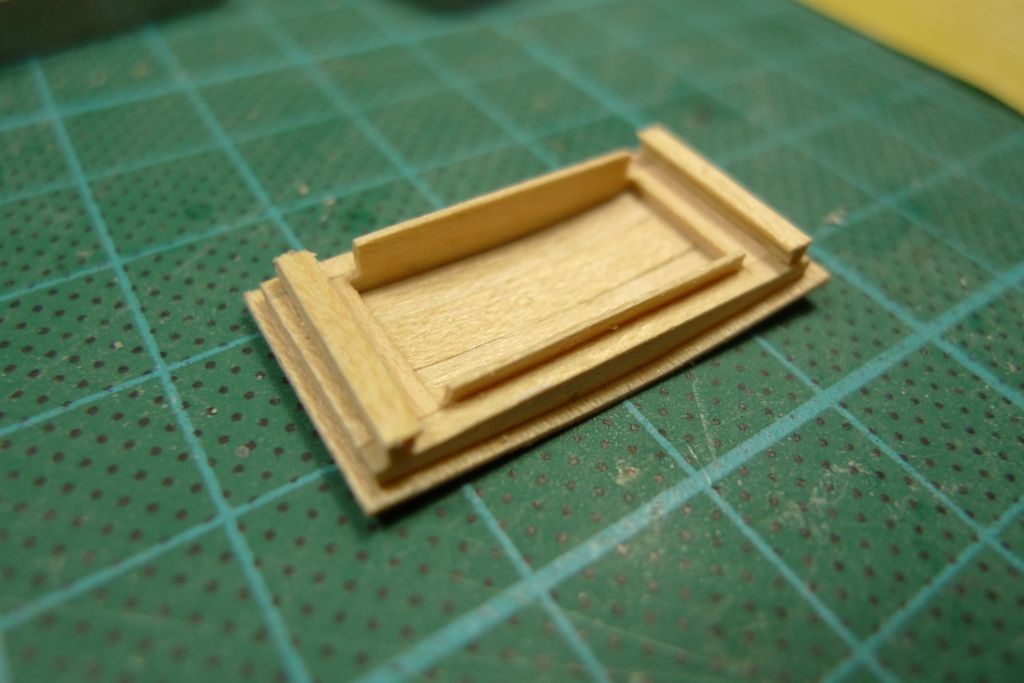
The gables were then joined by a number of transversal beams, at the bottom …
… as well as under the seat and around the curve of the back up to the front top, and floorboards added.
To be continued …
/Mattias
Edited By Banjoman on 10/12/2014 14:37:49
11 December 2014 at 08:34 #54259Banjoman
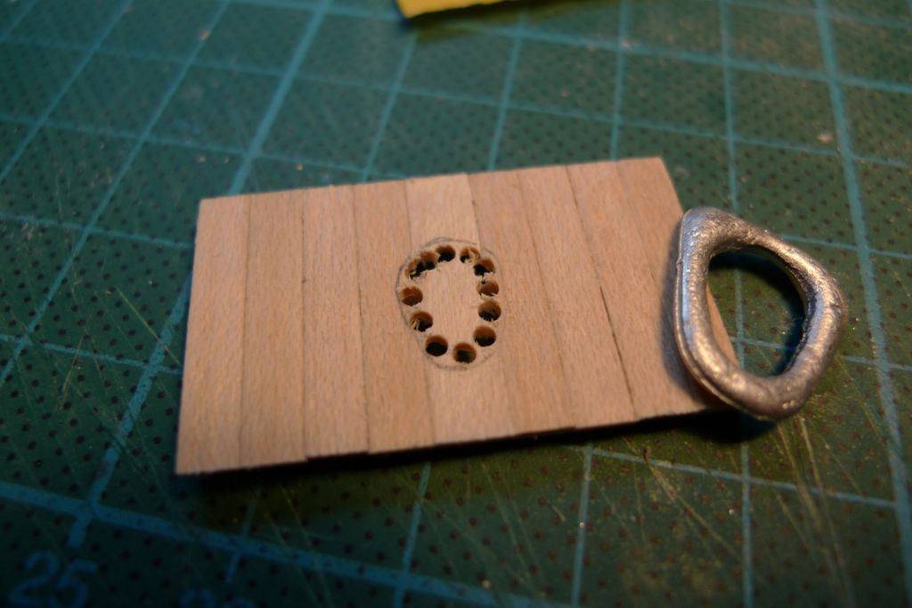
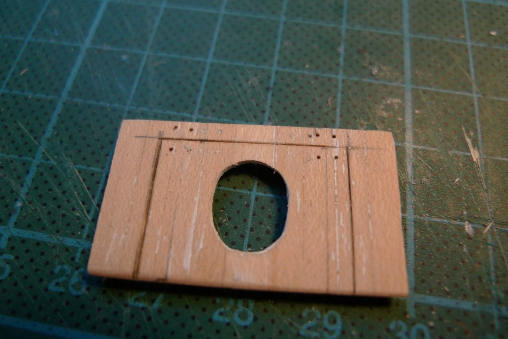
Participant@banjomanA series of short lengths of strip wood were glued to stringers, and the hole to go under the seat marked out and chain drilled …
… after which the whole thing was sanded to final shape and trim, a central lid cut out and holes drilled for the hinge nails.
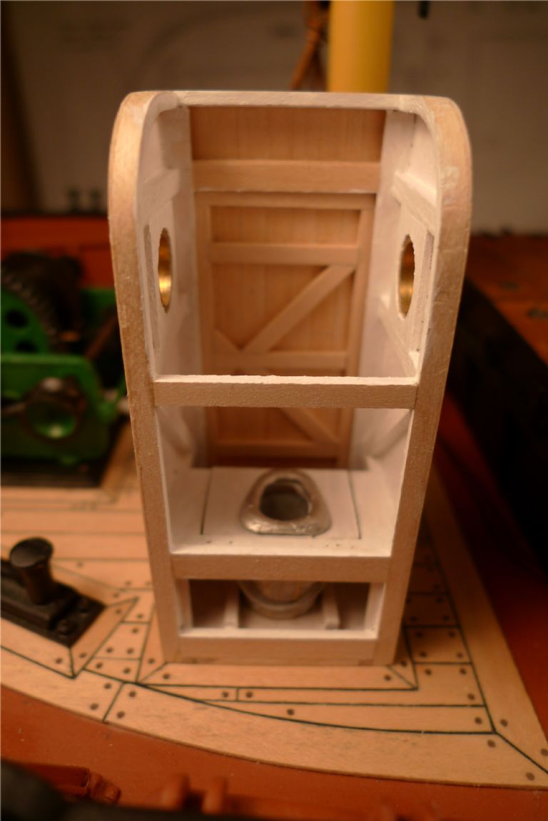
The privy interior was also painted white …
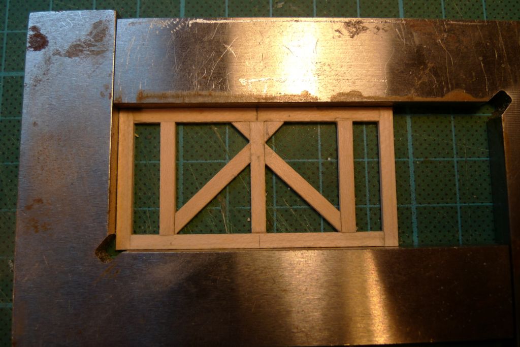
… a frame for the door was made up …
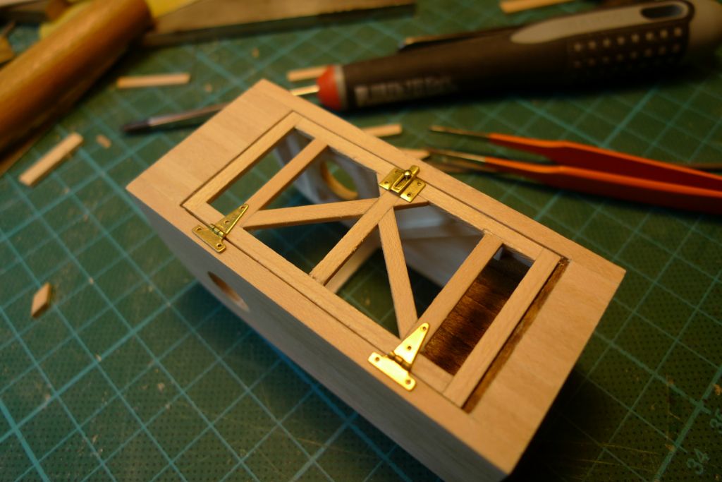
… dryfitted and checked for the placement of the hinges and the locks.
All hinges and other brass door paraphernalia was bought from Phoenix Models (**LINK**) a doll's house specialist with an excellent line in these fittings, including some quite small hinges.
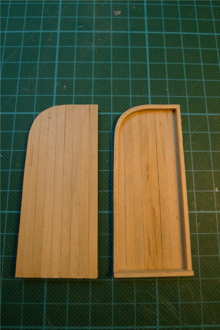
The door was then planked on the outside, in a similar way to the gables.
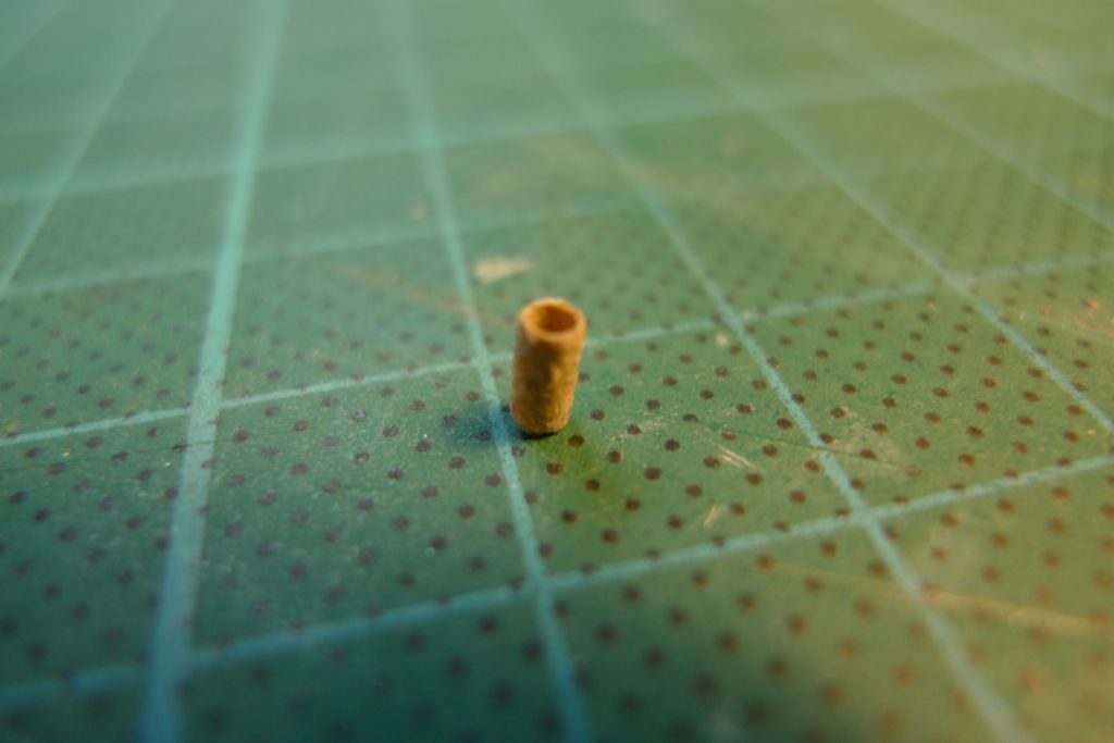
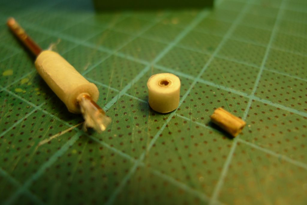
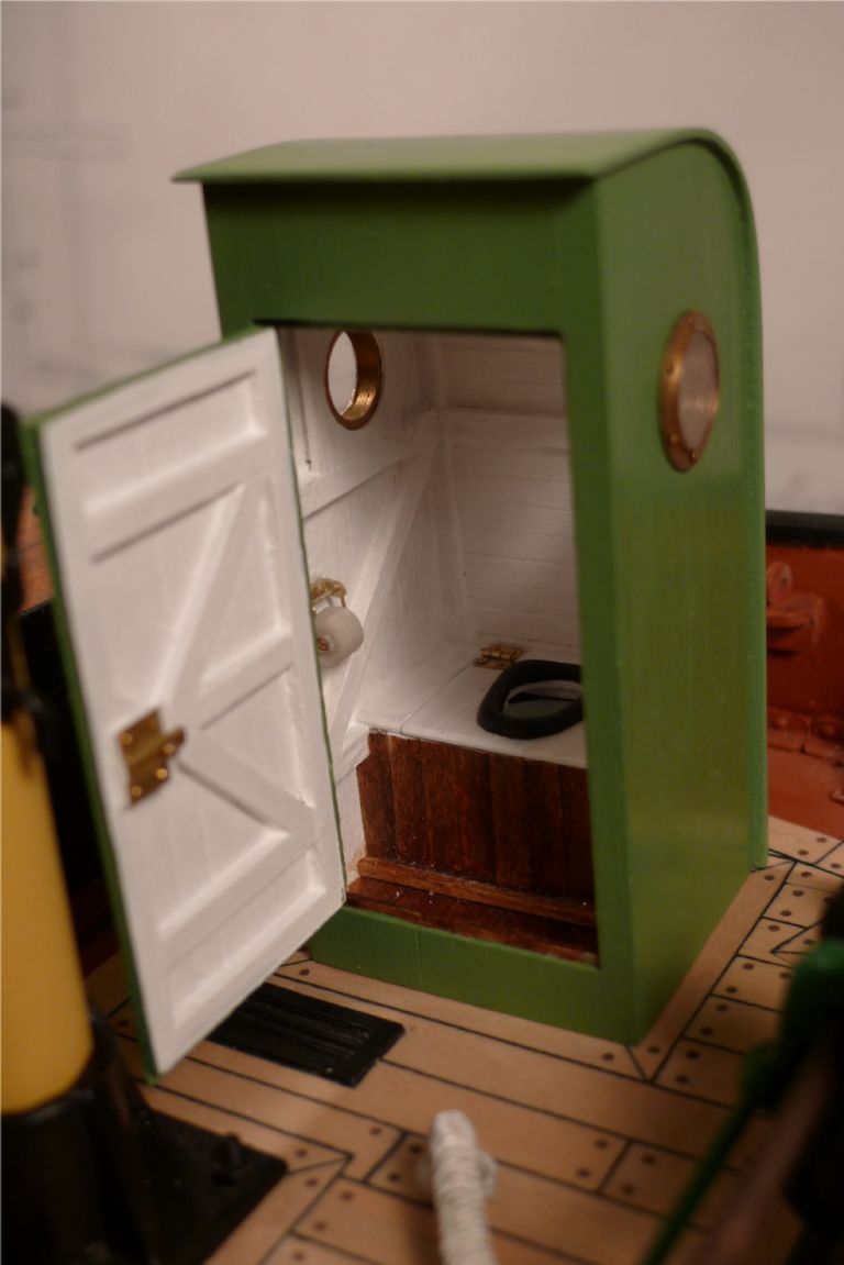
I also thought it would look rather nice to add a roll of toilet paper, and began by making up a centre roll from a 4 mm wide strip of brown paper that was rolled tightly around a 1.5 mm brassrod thinly clad in clingfilm (to stop glue from attaching to the rod) and glued with PVA. This resulted in a 4 mm wide cardboardy tube with an external diameter of +/- 2 mm.
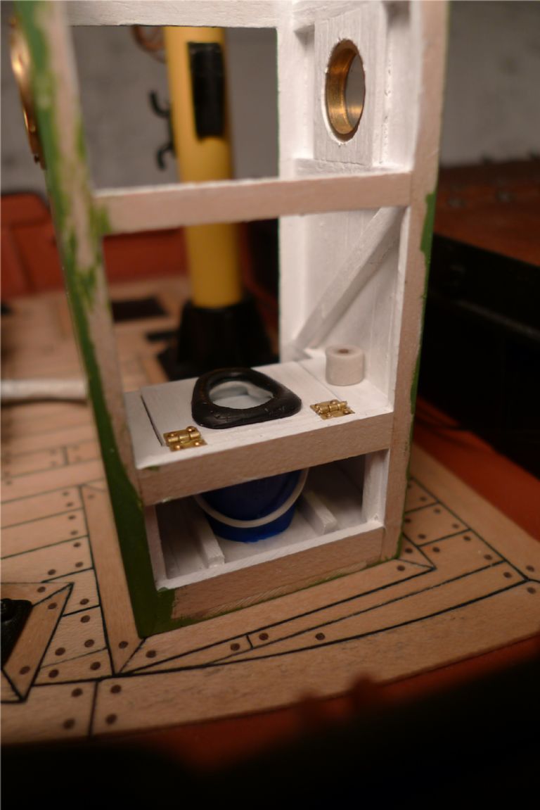
For the roll itself, I took a 2 mm rod, wrapped a small piece of clingfilm around it and then a strip of real toilet paper, wound as tightly as I could manage without the paper tearing. The toilet paper was then drenched liberally with thin CA glue which, once the whole thing had stopped (literally) smoking, resulted in a completely hard but still toilet paper-coloured roll 5 mm in diameter, from which a 4 mm wide slice could easily be sawed off, and into the centre of which the brown paper tube fitted nicely. Just enough of a striation remained on the edges of the roll to make it look rather like a roll of, well … loo paper.
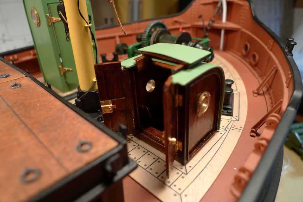
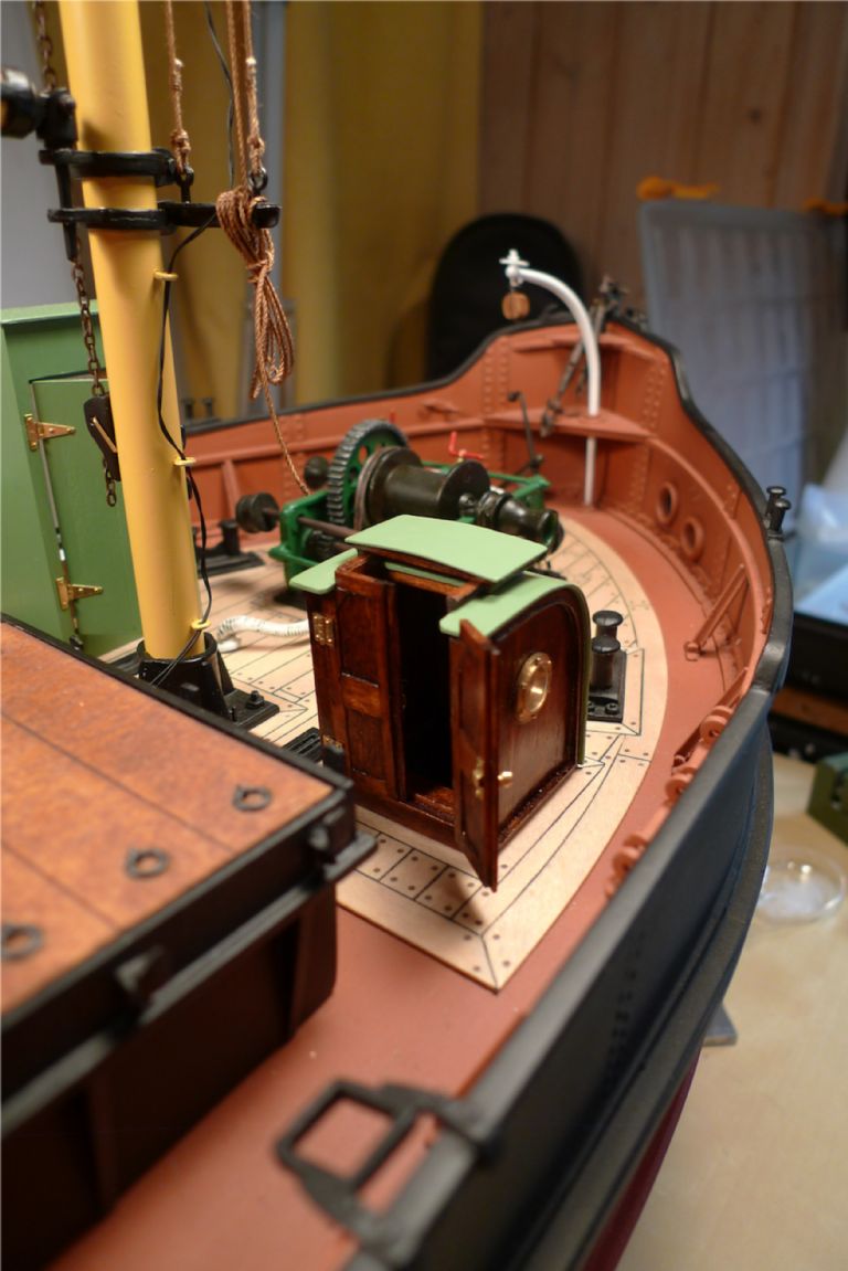
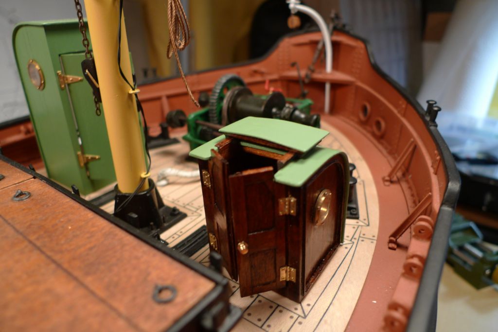
The bucket was painted dark blue on the outside and white on the inside, to give the impression of being the kind of enamelled article that was very common in the 30s, 40s and 50s. The ring was painted black and glued to the seat lid, which in its turn was attached to the main structure with a couple of hinges.
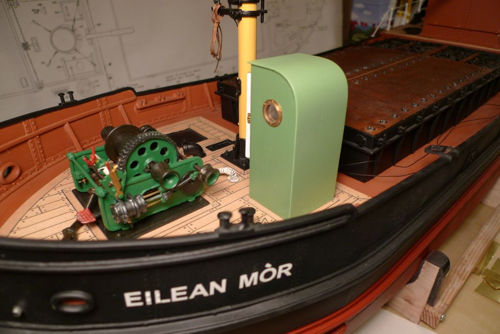
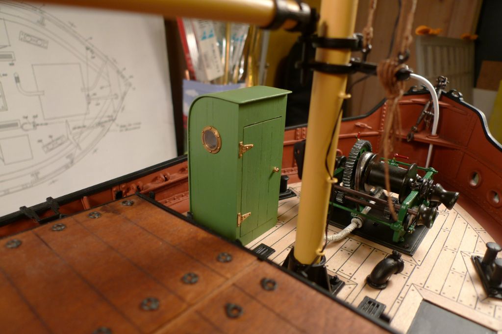
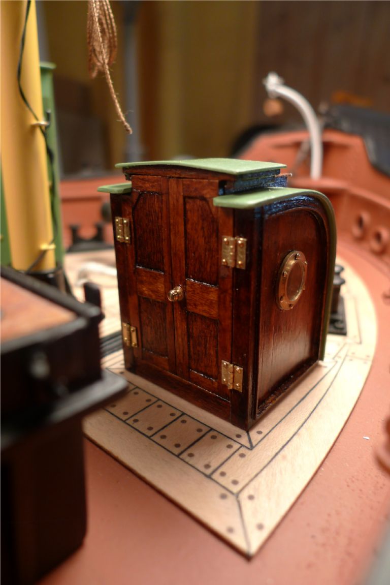
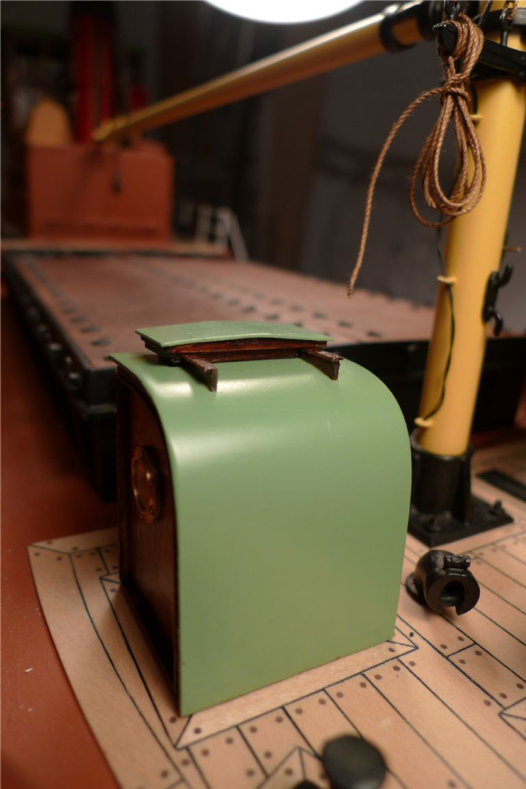
Next, the exterior was painted; the roof in the same green colour as the wheelhouse roof, and the walls and door in a slightly darker version (the same mix of paints but without any white added).
Finally the door was attached with a couple of hinges, and brass door knob added on the outside …
… a brass sliding lock on the inside and the toilet roll hung up on a small holder that I made myself from brass shim, brass wire and a small piece of centre drilled dowel turned down to about 0.9 mm diameter.
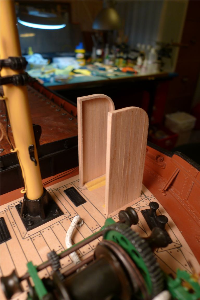
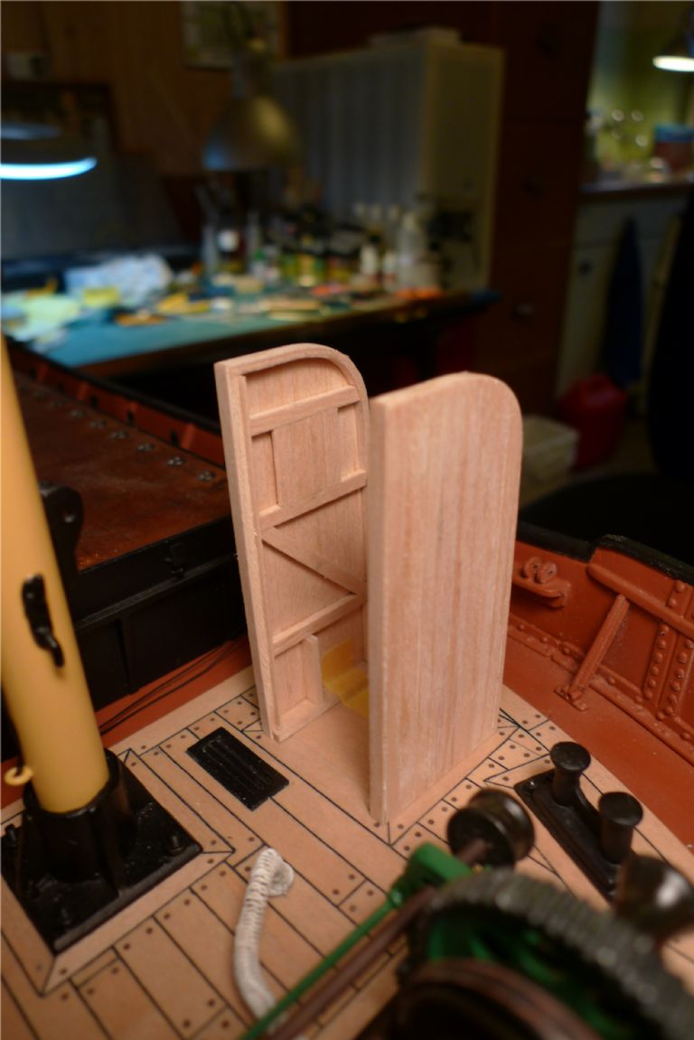
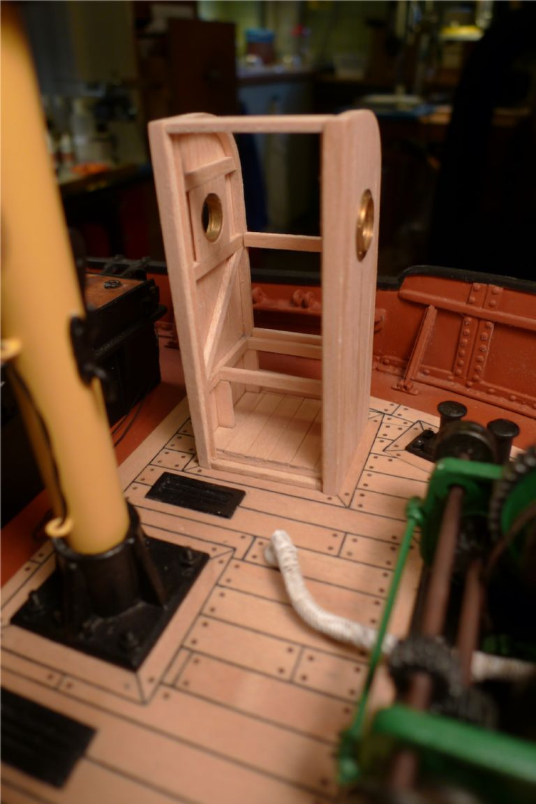
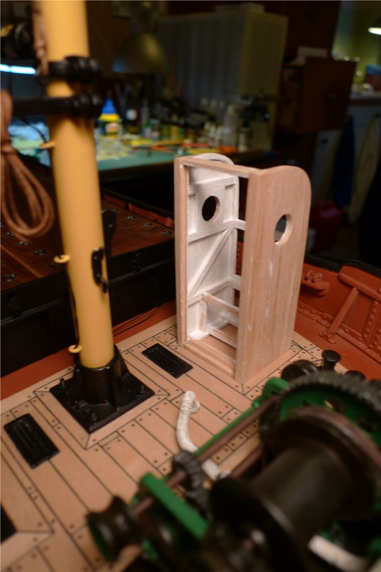
With this the privy was finished, but not yet glued in place, as it would then risk obstructing access for the latter work of rigging the mast; it is thus only dryfitted here.
To be continued …
/Mattias
Edited By Banjoman on 11/12/2014 08:35:02
Edited By Banjoman on 11/12/2014 08:38:19
11 December 2014 at 11:10 #54265Bob Abell 2
Participant@bobabell2More excellence !
You must be really enjoying this build?
Will you be getting it wet, when it's finished?……..Seems a shame to dirty it?
Bob
12 December 2014 at 07:06 #54286Amy jane September
Participant@amyjaneseptember49770Well dunny…..
 12 December 2014 at 10:04 #54291
Banjoman
Participant@banjomanThank you ever so much, Bob and Amy jane! (And yes, Amy jane, I know the word "dunny"
 )
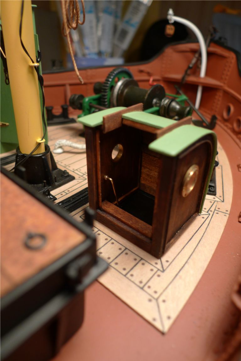
)After the privy came the companionway shelter, the construction of which began in a similar manner by laminating and bending the back beams in the same former that I'd used for the privy.
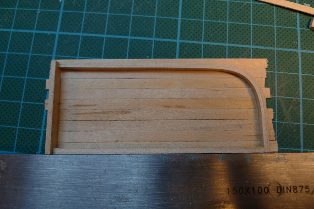
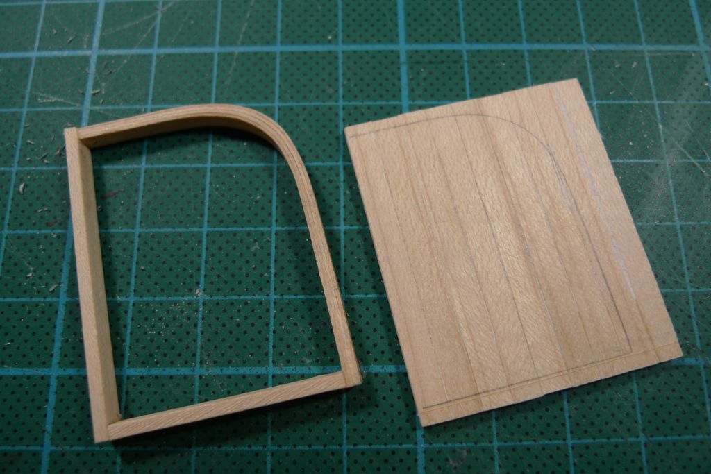
However, instead of external single layer planking, as on the privy, I thought that the shelter should look a slightly more elaborate structure, and I therefore decided to work with panelling set inside the gable frames and to this end made up two sheets of glued-together 2×4 mm maple strip lengths.
The gable frames were put together in the same way as for the privy …
… their internal shapes transferred to the panels …
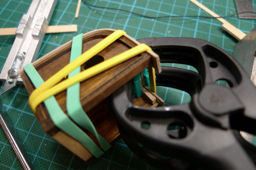
… which were then cut out, trimmed and glued into the frames. To further vary the external shapes, some 0.5 mm thick maple strip was glued all around the frame edges, both to cover any minor gaps and to add some … well … elaboration.
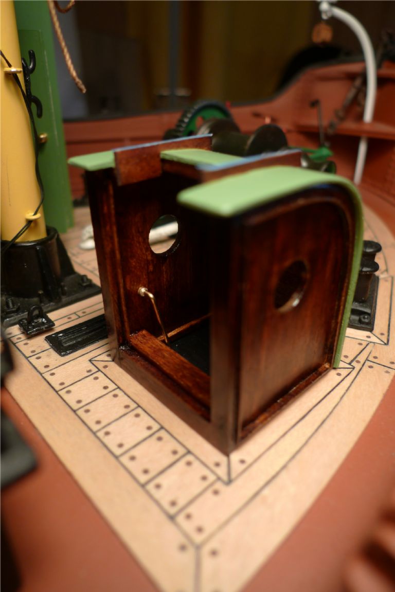
After sandwich drilling the gables for the portholes, again just as I'd done when building the privy, the two sides were stained and the joined together by a series of transversal beams.
By now I had also decided to deviate from the kit prototype, by having not only doors on the shelter but also a short sliding hatch on top of it, of the kind that one often sees on companionway shelters to facilitate in- and egress. The front beam shown here is thus but temporary, and was included at this stage just to make the assembly that little bit more stable until the glue had set.
It was then cut away, and the roof (with the corresponding piece also cut away) added.
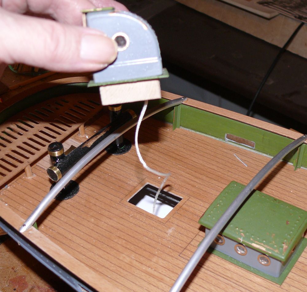
During the preceding planning phase, I'd been fairly undecided as to whether or not I should actually open up the deck under the shelter in order to have at least the upper part of an actual companionway disappear down into the darkness of a box built under the deck.
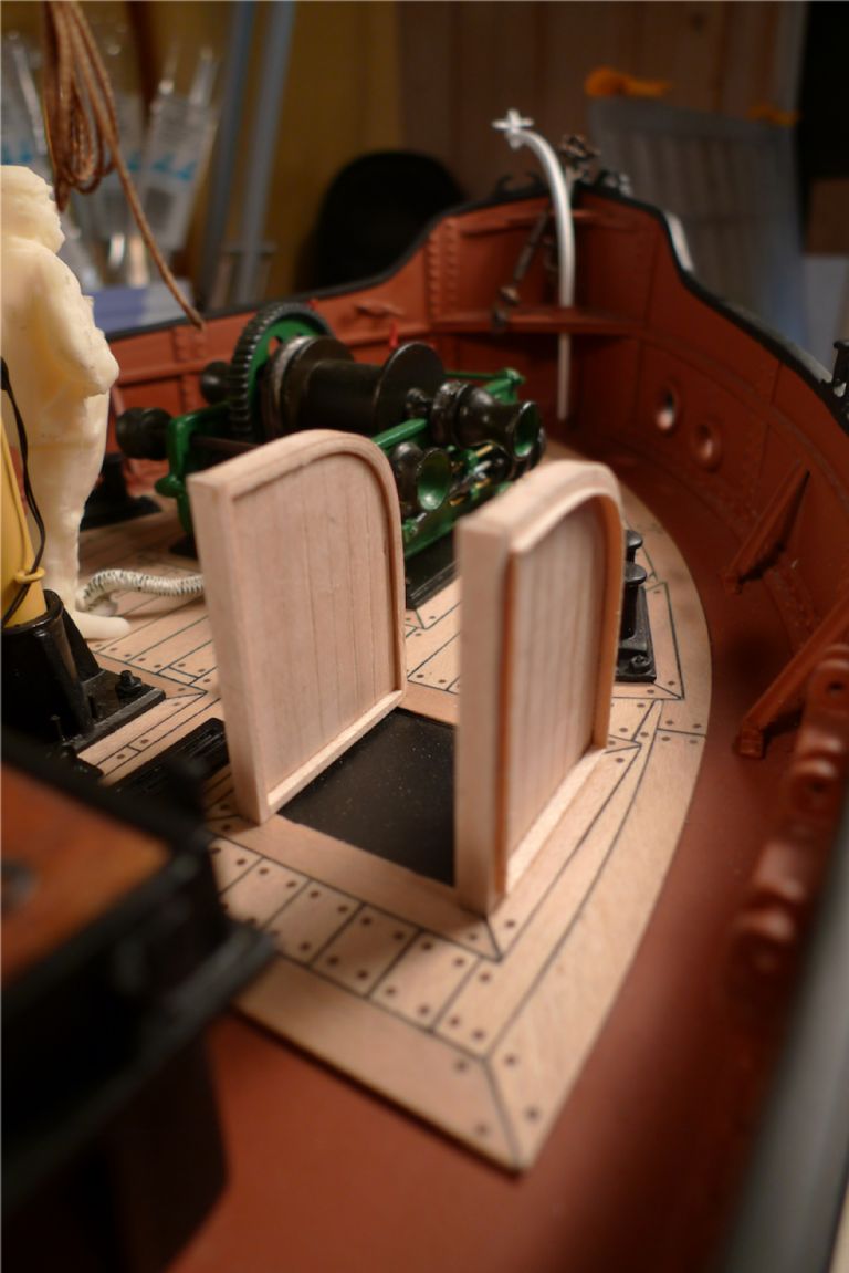
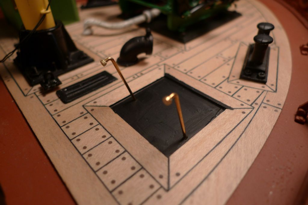
In the end, though, I opted for the simpler and more guaranteed-to-be-watertight solution of just painting the bit of deck under the shelter black. I did, however, add the two top steps of the putative companionway just inside the door opening.
The roof was painted in the same green colour used for the privy roof, and panelling added to its inside. Likewise, two pieces of wood were glued onto the roof for the top hatch to slide on.
To help the illusion of depth hopefully created by the black underpainting, two handlebars were made up from brass rod with wall mount fittings created from a very short piece of brass tube ground to shape.
Two holes where the brass rod would be a good push fit were drilled at a slight angle into the deck …
… and, with the shelter in place, turned 90 degrees for the wall mount fittings to sit against the panelling.
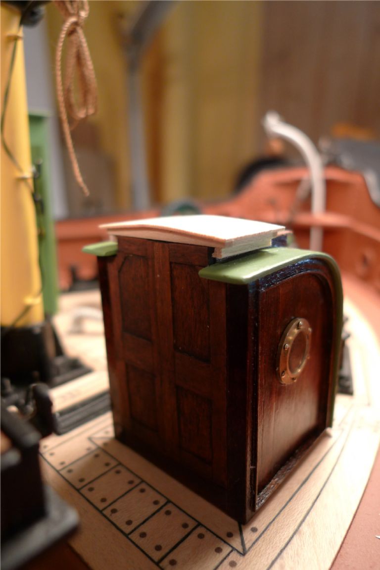
Personally I think that the illusion works well enough, and that it looks pretty much as though there really were an opening there with a companionway going down into the fo'c'sle.
To finish this stage of the shelter build, the stained wood was given a couple of coats of clear varnish.
To be continued …
/Mattias
Edited By Banjoman on 12/12/2014 10:13:17
12 December 2014 at 10:05 #54292Banjoman
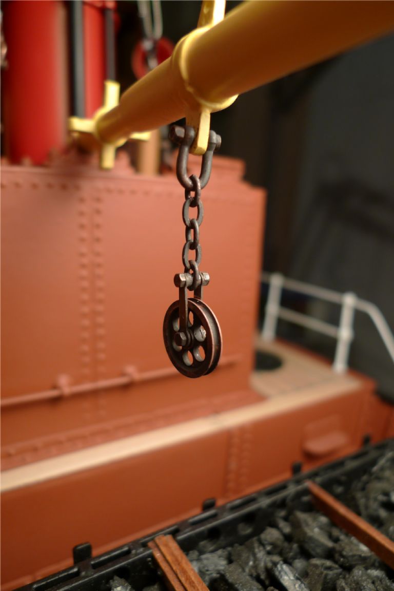
Participant@banjomanConcurrently with the construction of the companionway shelter, I spent some of the time waiting for stuff to set or dry to also sort out a couple of gin blocks.
I'd been planning all along to use the excellent working gin blocks produced by the Polish company RB Model. Unfortunately, when I needed them their single gin blocks could not be had anywhere for love nor money, and seemed to be out of stock wherever I looked. I even went so far as to write to RB Model and ask, and found out that one of their machines had gone on the blink rather badly during a recent move of their workshop, and that for the time being they could not produce these blocks. Oh, bother. (They are still not back in production, by the way.)
The RB Model double gin blocks, however, were in plentiful stock just about everywhere, but I did not want to use double blocks on the model, as it seems quite clear from period photos that puffers as good as always were rigged with single whips.
In the end I therefore bought a couple of the double gin blocks, and converted them to singles by drilling out the centre pins to take the blocks apart, and reassembling them with a couple of RB Model M1.2 nut-and-bolt sets instead of the pins, adding two very short pieces of brass tube as distances on either side of the short chain from which the block hangs. The whole assembly was then shackled to the boom spider band.
The same procedure was applied to the gin block for the wire-and-chain topping preventor. Here it is just test rigged, though, with a piece of rigging thread and some chain.
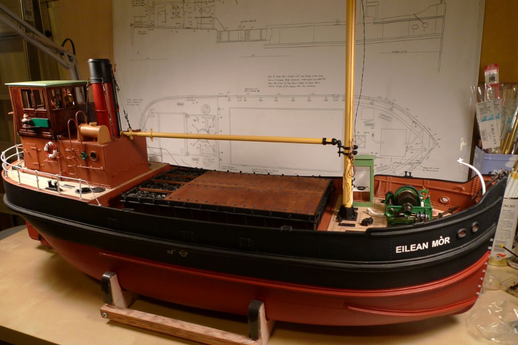
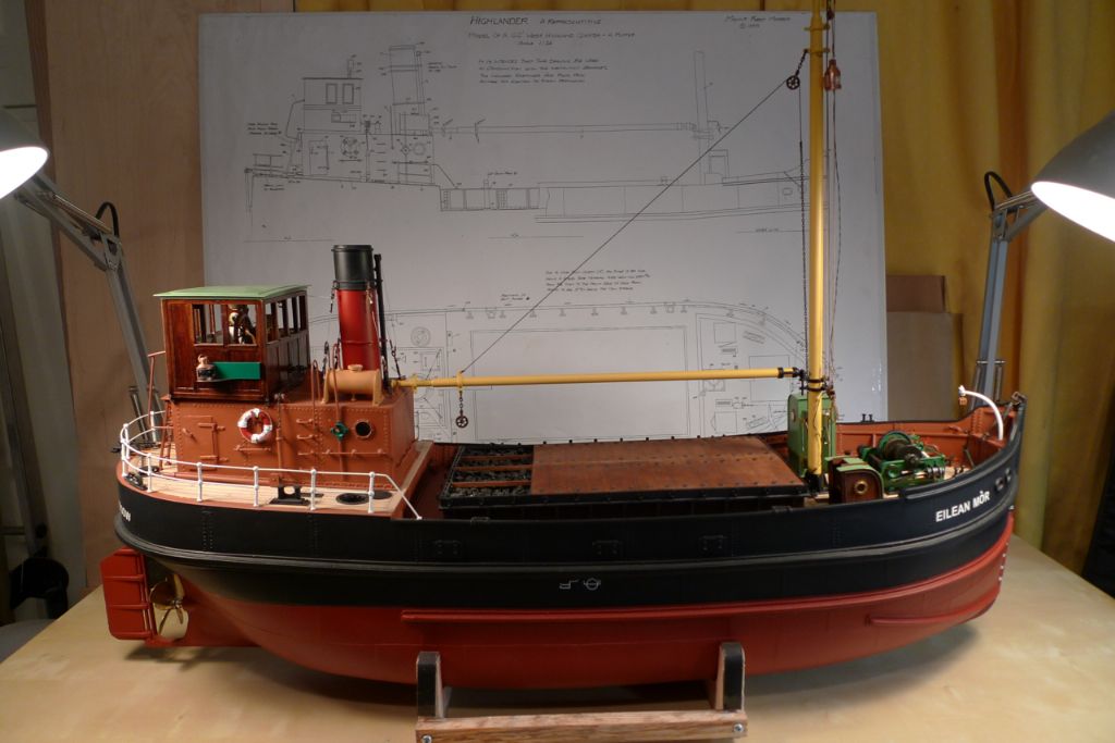
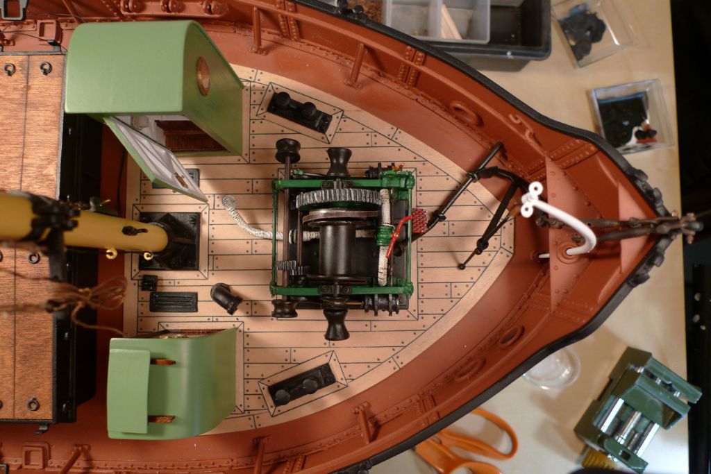
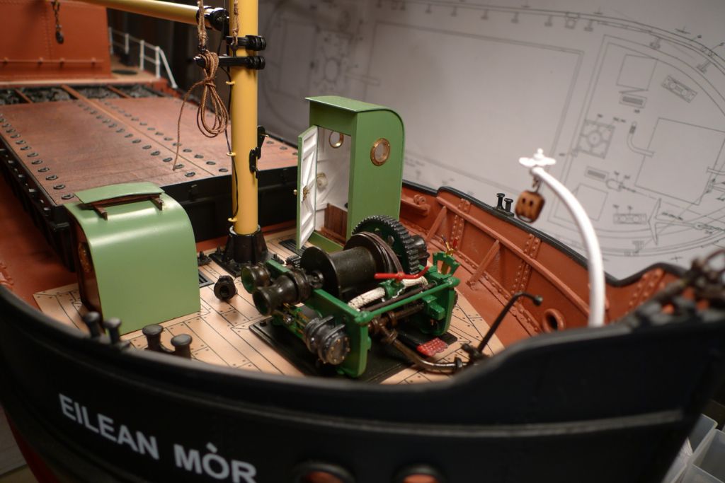
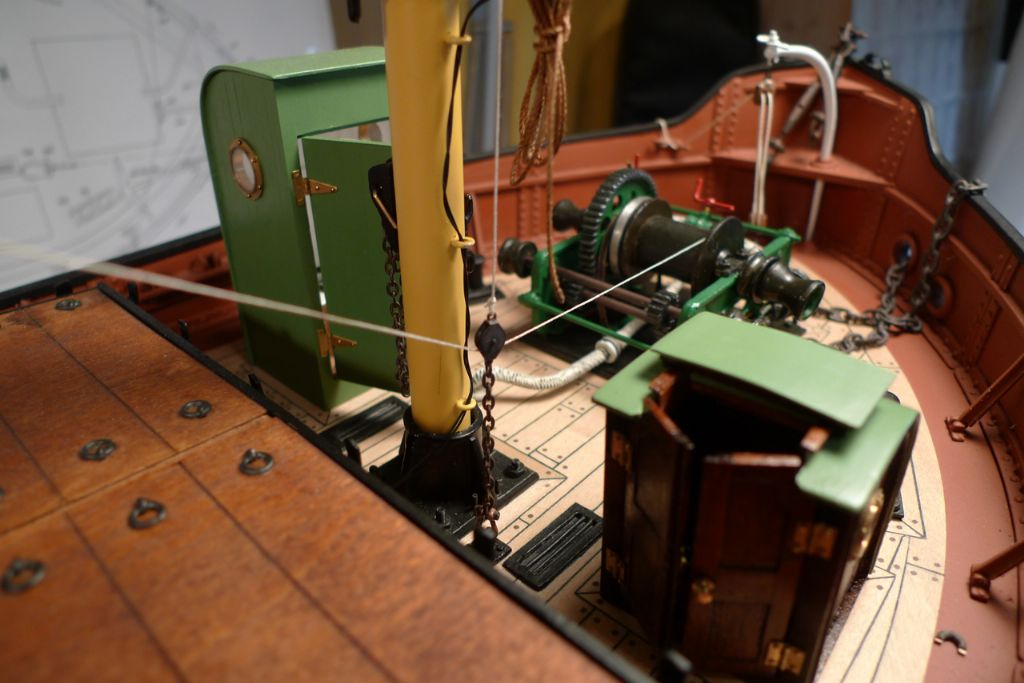
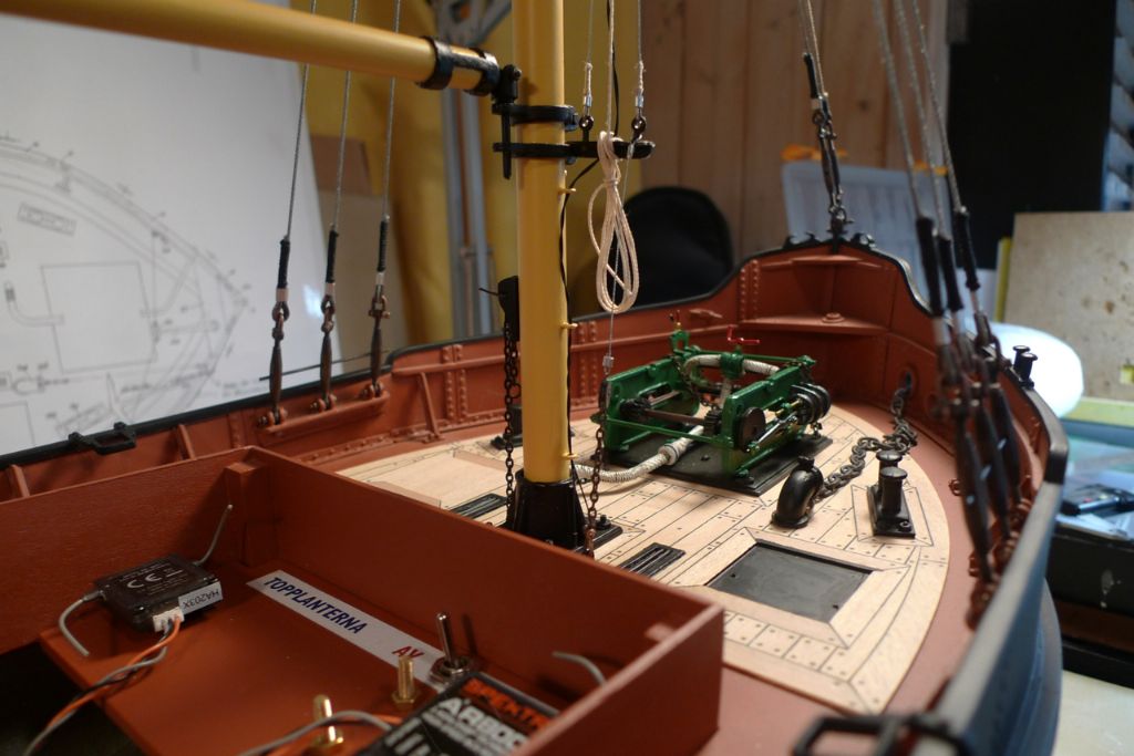
So… with winch, privy and shelter in place the foredeck now began looking more like the slightly overcrowded real thing it ought to ressemble …

To be continued …
/Mattias
Edited By Banjoman on 12/12/2014 10:08:30
12 December 2014 at 15:05 #54295Banjoman
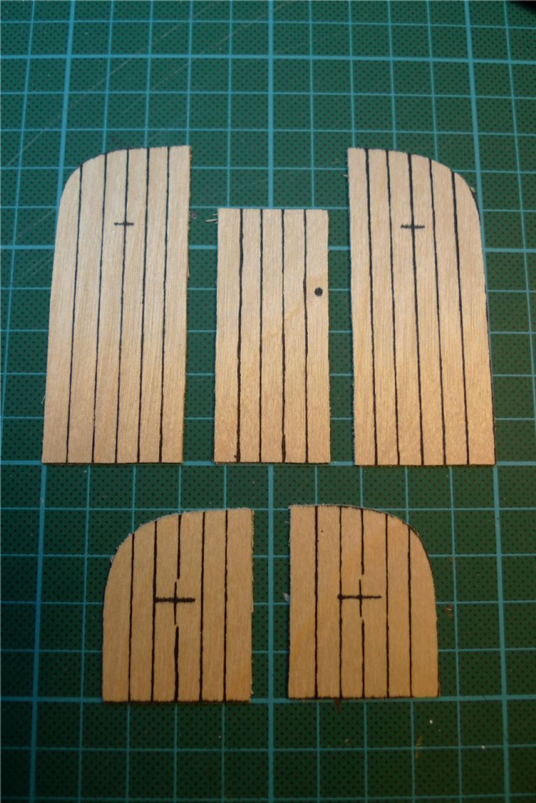
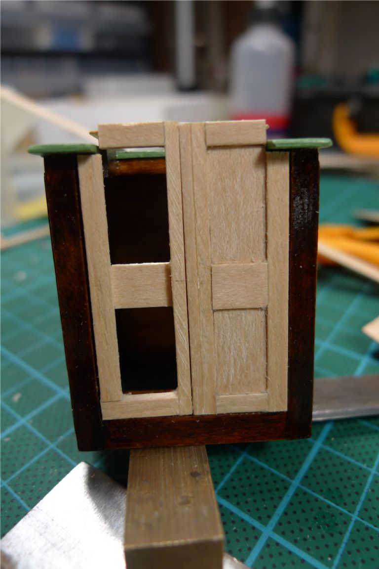
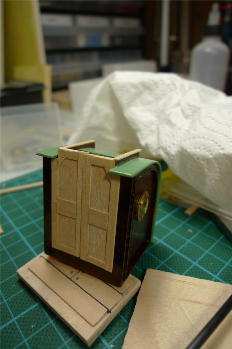
Participant@banjomanThe doors for the companionway shelter needed to be overlapping, and, in order to fit around the opening for the top hatch, also not just rectangular.
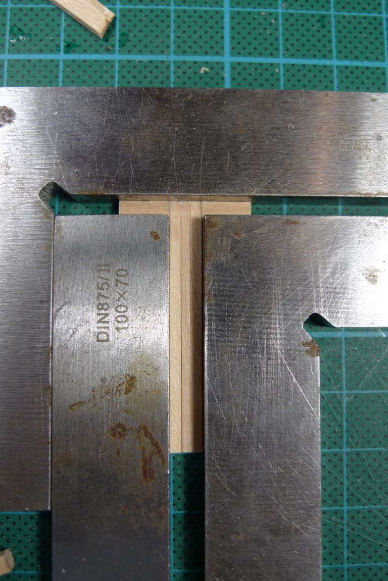
The doorframe construction therefore began by glueing together the overlapping centre posts with their respective frame tops …
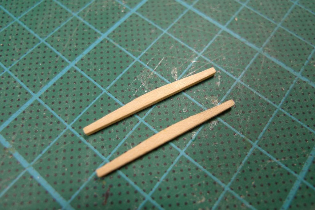
… to which was added the bottom frame pieces as well; while waiting for the glue to set, I also roughly shaped the front and back pieces of the hatch frame.
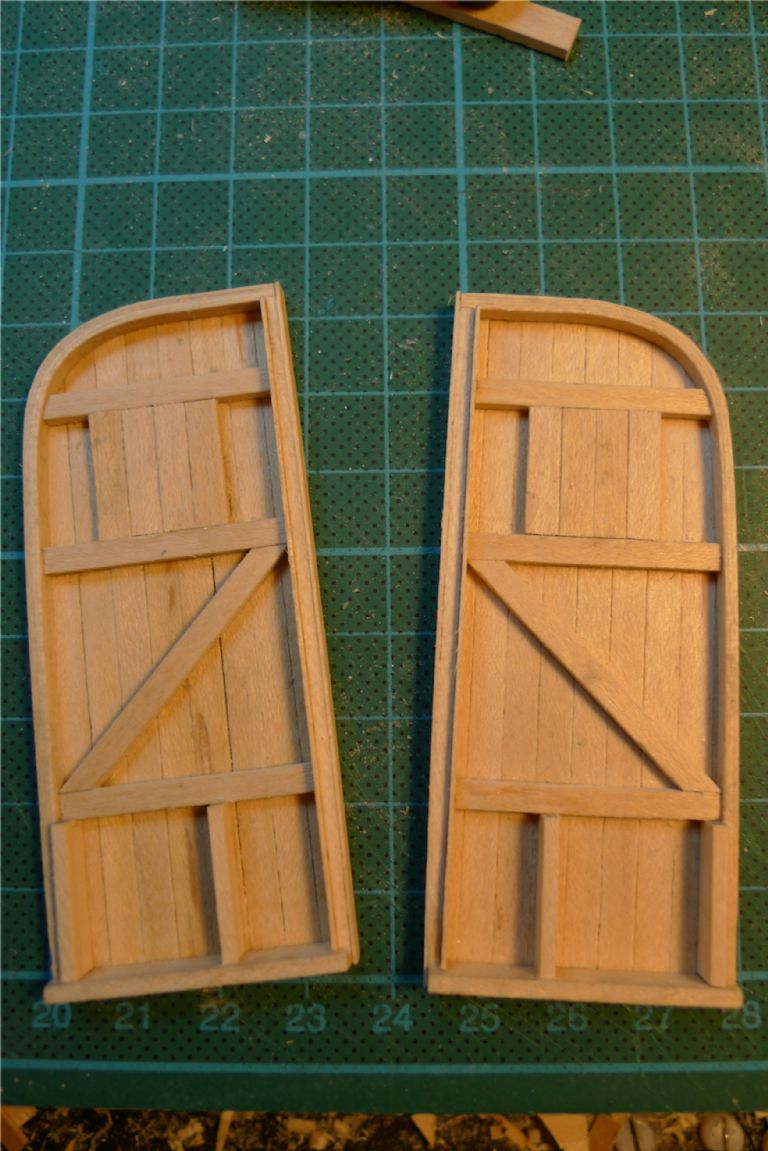
The part and starbord frame posts were then added, as well as door panels and wider centre frame parts (actually made up from thinner strip, just glued to the back and front of the panel.
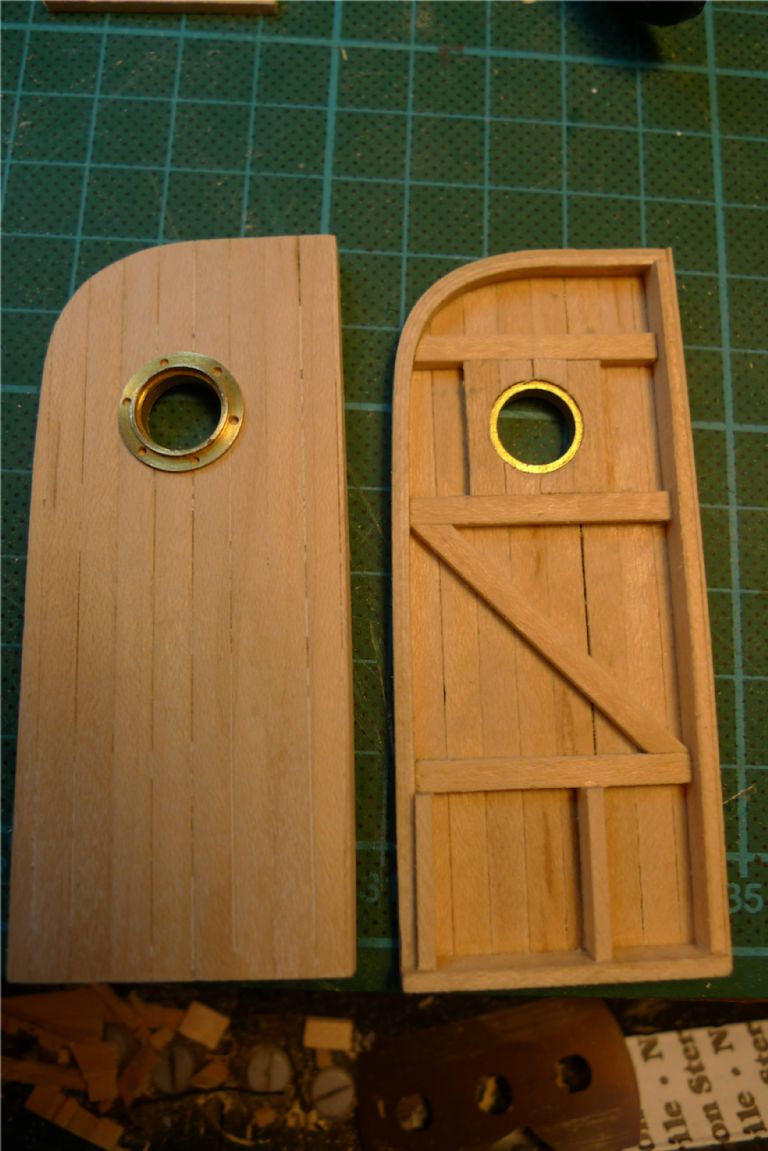
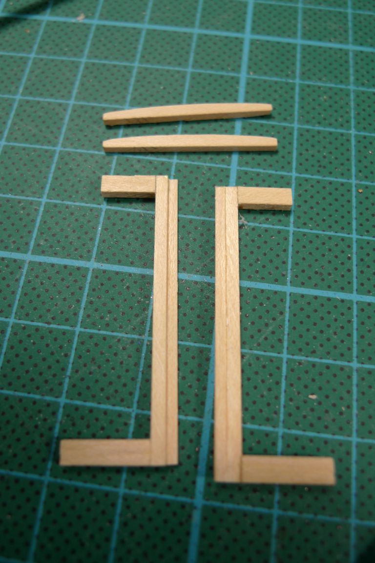
At this point I realised I'd made a minor error, in making the lower frame parts the full width of each door half, as seen on the door half to the left in the below photo. For better symmetry with the frame tops, and thus better looks, it would be preferable to have both tops and bottoms sit, as it were, between the verticals.
The glue joints were thus broken open and the relevant pieces replaced to make both door halves look like the one to the right in the picture above; corner reinforcements were then added in the top outer corners.
Strips were also glued onto the tops of the hatch gliders, to serve as counterholds for the hatch.
The two front and back hatch frame blaks were sanded to final shape …
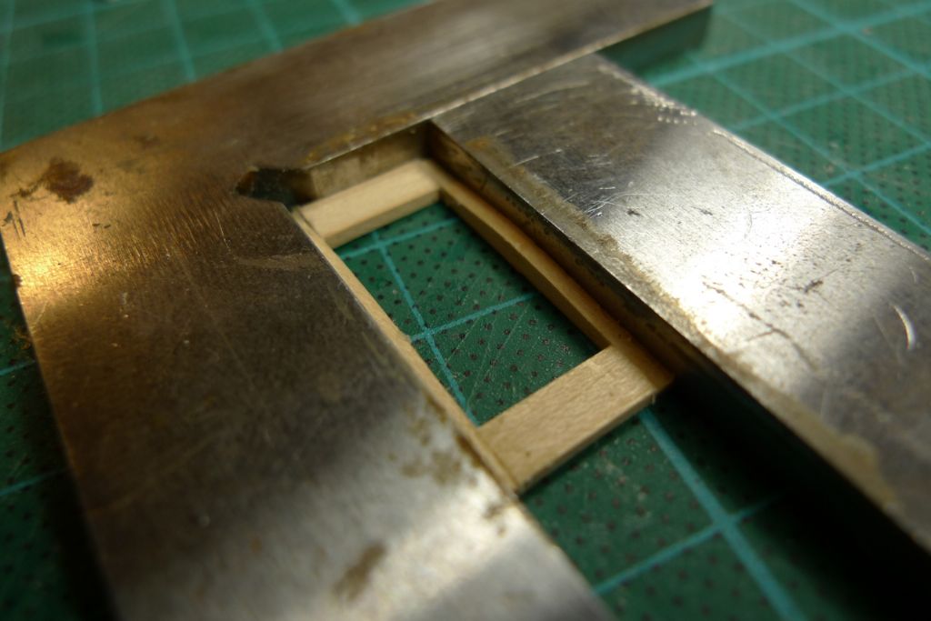
… joined together with two shorter pieces of strip …
sanded down to follow the front and back curvature, and a roof blank cut from maple sheet.
This was the glued in place …
… the necessary counter pieces made up and glued to the underside, to fit around the gliders, front and back stops added as well as some interior panelling …
… to produce the following result.
The hatch was then stained, painted and varnished in the appropriate places, the doors attached with hinges …
…
…
…
… and forseen with a sliding lock and a brass knob …
…
…
To be continued …
/Mattias
12 December 2014 at 15:11 #54296Banjoman
Participant@banjomanOh, and I completely forgot to say in reply to Bob Abell's question yesterday that I most certainly intend to let this boat wet her feet once she's done!
Yes, I dare say I will get her a tad dirty and/or shall risk breaking this, that or the other, but it would on the other hand be rather a waste of both effort, money and equipment to have put drivline and all in and then only take her for a spin in the baththub, eh … ?!

/Mattias
12 December 2014 at 16:28 #54301Bob Abell 2
Participant@bobabell2Hello Banjo
The problem with sailing your model on the club pond, is that in the event of a collision, it will probably got to the bottom!
I made the Graupner paddle boat some time ago and placed empty plastic milk bottles inside, as a precaution and also a hidden marker buoy
Alas, it's a bit late now
Bob
12 December 2014 at 17:59 #54307 Colin BishopModerator@colinbishop34627
" The problem with sailing your model on the club pond, is that in the event of a collision, it will probably go to the bottom! "
Sorry Bob, but that's nonsense! Model boats collide with each other all the time and a sinking as a result is very, very rare indeed! The most than normally occurs is a bit of scratched paintwork or maybe a fitting damaged or knocked off in extreme cases all of which is easily put right.
Or is it just that you are a lot of homicidal hooligans 'oop North?
Colin
12 December 2014 at 18:14 #54308Bob Abell 2
Participant@bobabell2You are incorrect there, Colin!
If a plastic / fibre glass / ABS based hull gets hit broadside…….It will roll over, fill with water and down she goes!
It happens quite often on our pond, when the speedy boats are mixed with the slow boats
We`ve got a member who has done it three times at least……The last incident cost him a three figure sum!
He has developed quite a skill, retrieving sunken models with the dinghy oar!
Bob
12 December 2014 at 19:24 #54316 Colin BishopModerator@colinbishop34627
As I said, hooligans then!
We are more civilised down here.
Colin
12 December 2014 at 20:07 #54317Banjoman
Participant@banjomanWell, I shall have to hope, then, that the club I'm thinking of joining once the build has been finished doesn't count amongst its membership too many broadside louts …
/Mattias
13 December 2014 at 16:59 #54327Banjoman
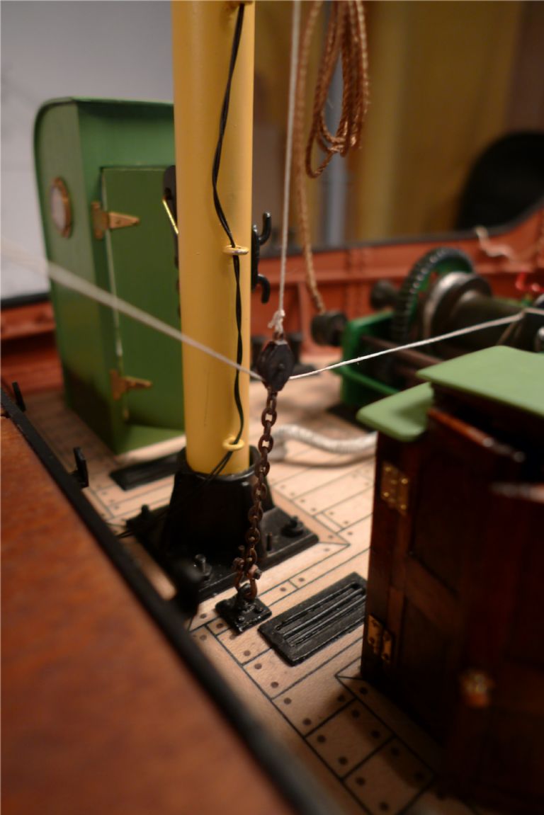
Participant@banjomanWith most of the foredeck furniture more or less finished, it was time to start looking into the rigging of the mast.
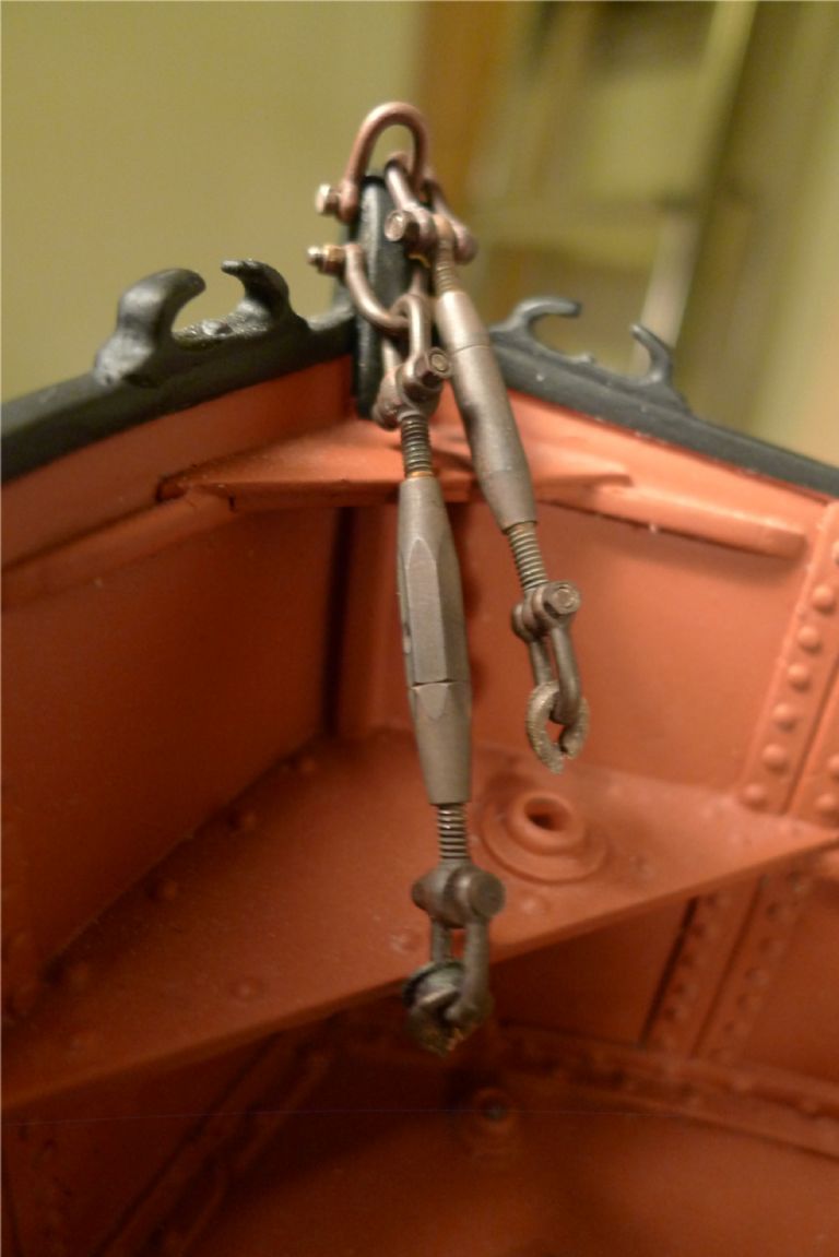
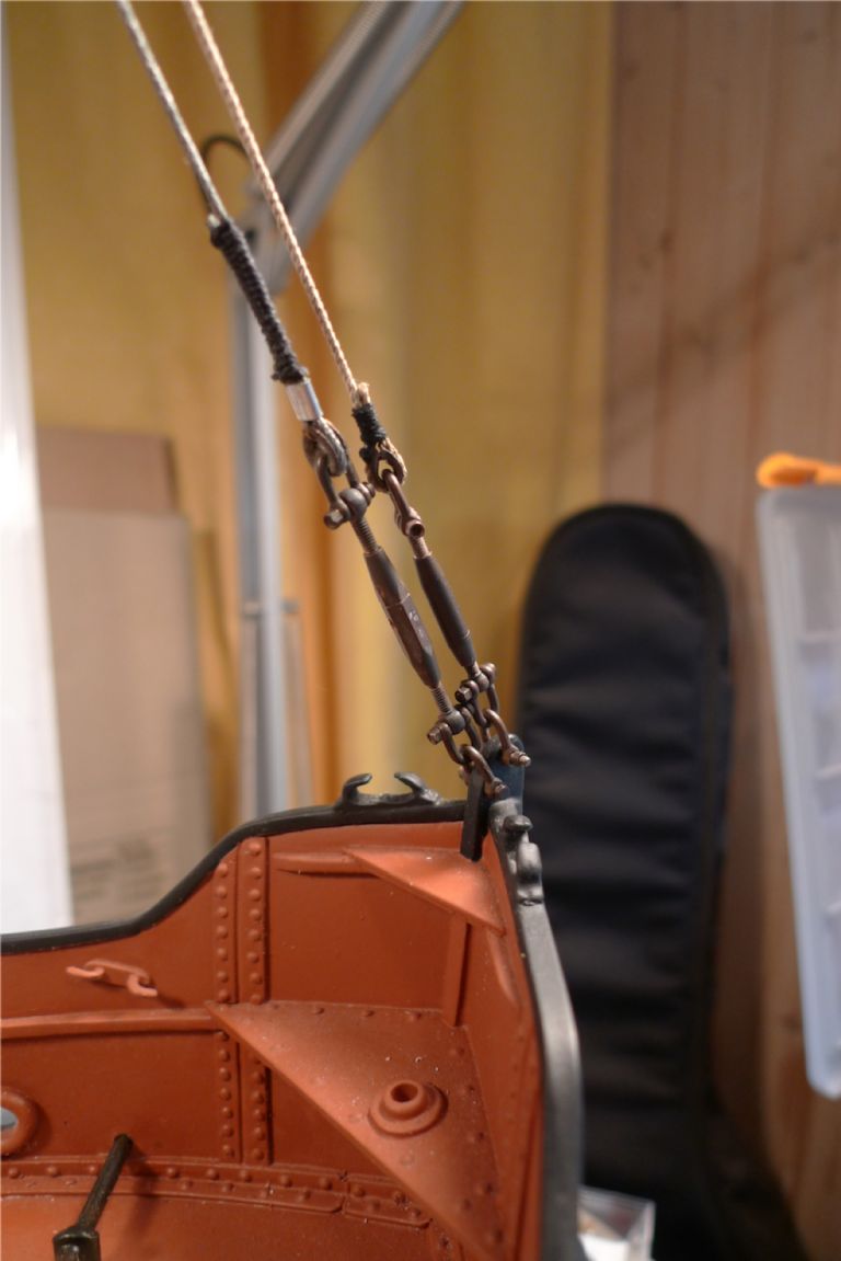
A couple of bottlescrews were shackled onto the sternpost, with thimbles shackled to the other end. As can be seen in the photo below, these thimbles (which are cast in bronze, and furnished by Modelling Timbers) have had to be cut open at one end, in order to be fitted. While they pass around the shackle shank without any problems, the eyes at the ends of the shank are too large to pass unless the thimble is first bent open a bit, for which they of course had to be cut first.
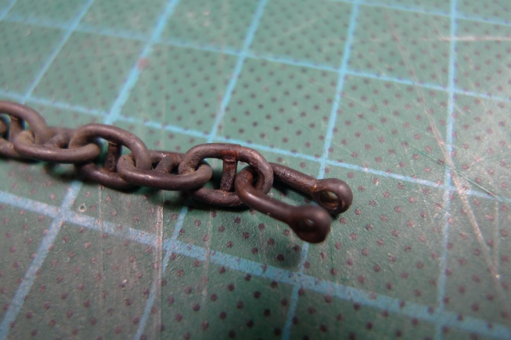
Likewise, it was impossible to pass a shackle eye through the end link of the anchor chain, so the link was sawed through with a very thin razor saw just next to the stud, bent open and then, with the shackle in place, bent back again. In a real close-up, such as in the photo here, one can just see that there is an ever so slight misalignment at the point of the cut; however, at normal distances one cannot really distinguish it.
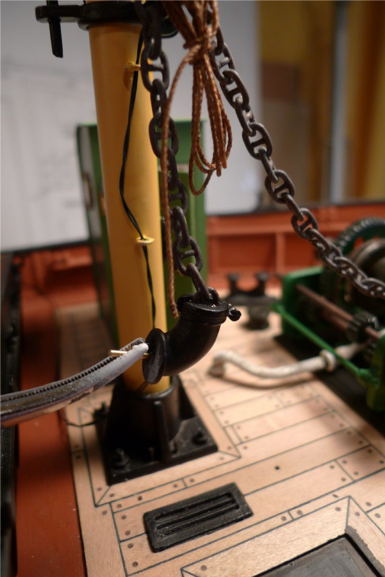
The anchor chain was then epoxy-glued into the chain locker pipe. The photo does not show the pipe in its actual place (duh!); here I had just suspended the chain from the lower toplight outrigger to keep it straight enough that the next link after the one glued in did not touch the glue while it was going off.
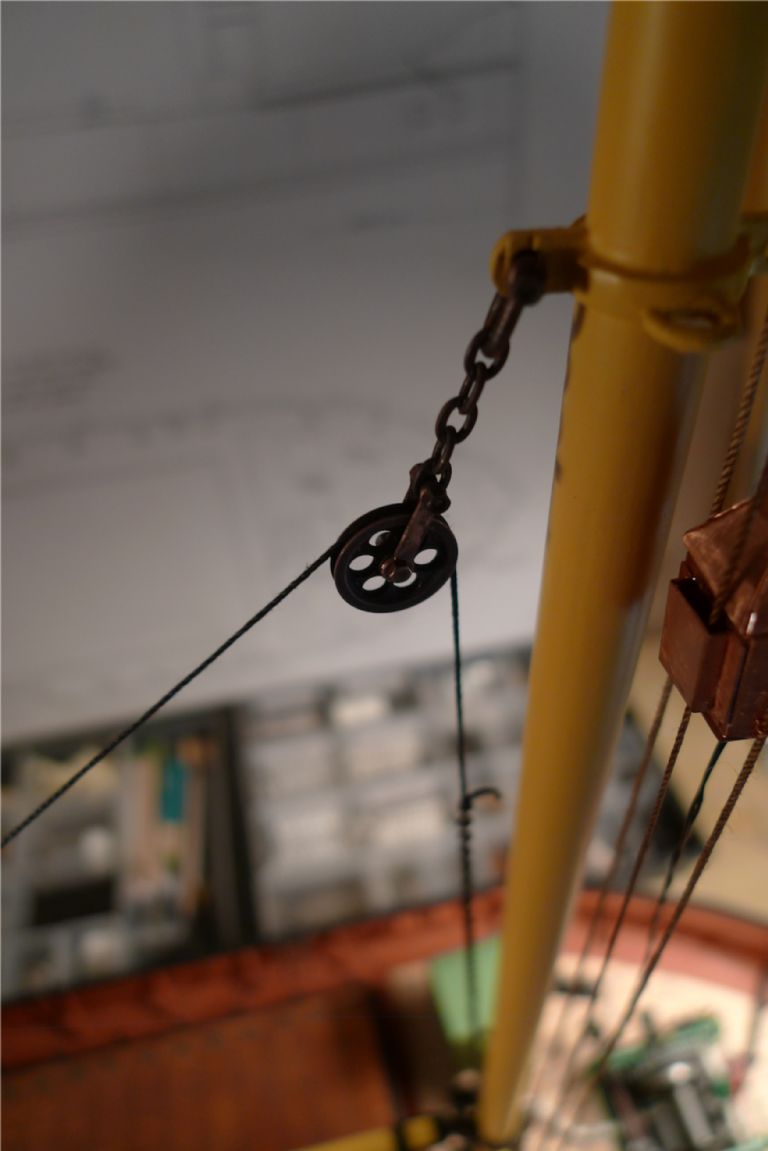
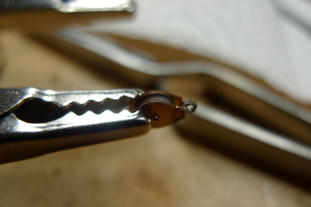
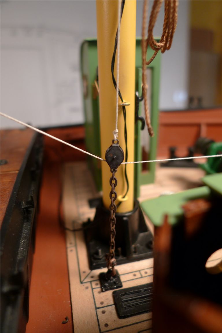
I also made up a working lead block for the whip wire from one of the RB Model etched brass kits. The only slightly tricky bit here was soldering the ends together without getting any noticeable solder outside of the actual joints.
The block was then attached to a suitable length of chain and shackled to the kit provided white metal ringbolt, in its turn glued in place on deck with a piece of brass wire set into the bottom and going into a hole drilled in the deck for a stronger joint.
Although the lead block would in principle be kept in proper position by the tension of the wire whip, I nevertheless decided to also string it up from above for more stability. At this stage, though, I only did a temporary job with a piece of rigging thread, to be replaced later by some steel wire.
Likewise, the test whip was also just some thread to check the principle of the thing.
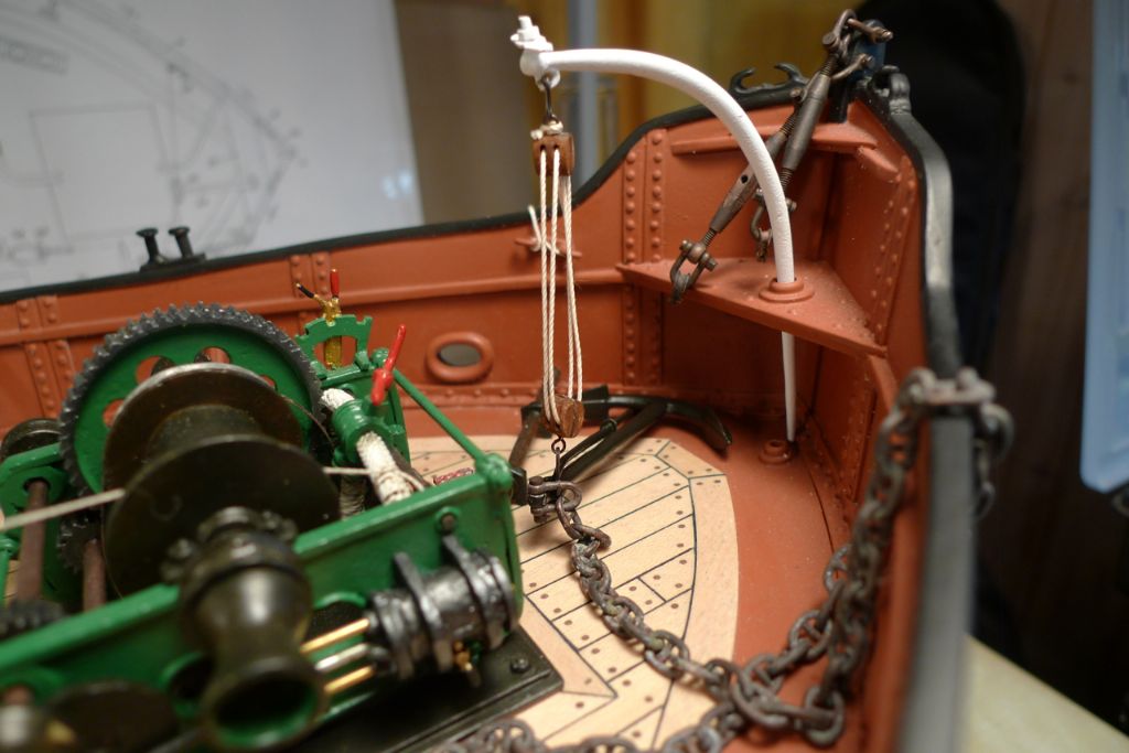
The anchor chain was shackled to the patent anchor, the end of which was suspended with a double tackle from the davit.
With the temporary whip and preventor in place, the boom was elevated slightly and a small weight (the bucket of coal, as a matter of fact) hung from a hook at the end of the whip …
… to check the general suitability of the set-up. As it turned out, I was quite happy with it, and would thus at a later stage be able to replace the temporary bits of string with real steel wire.
To be continued …
/Mattias
Edited By Banjoman on 13/12/2014 17:00:22
Edited By Banjoman on 13/12/2014 17:03:39
13 December 2014 at 20:31 #54331Bob Abell 2
Participant@bobabell2I like the agricultural tackle, Banjo
Real down to earth tackle modelling!……….( Can you understand my old English sayings, Banjo? )
Just having some fun, winding you up!……lol
Your model is as pretty as a picture………Really nice to see
Bob
13 December 2014 at 22:20 #54334Banjoman
Participant@banjomanOf course you're winding me up, Bob – isn't that what chains are for, anyway?!?

/Mattias
14 December 2014 at 17:34 #54342Banjoman
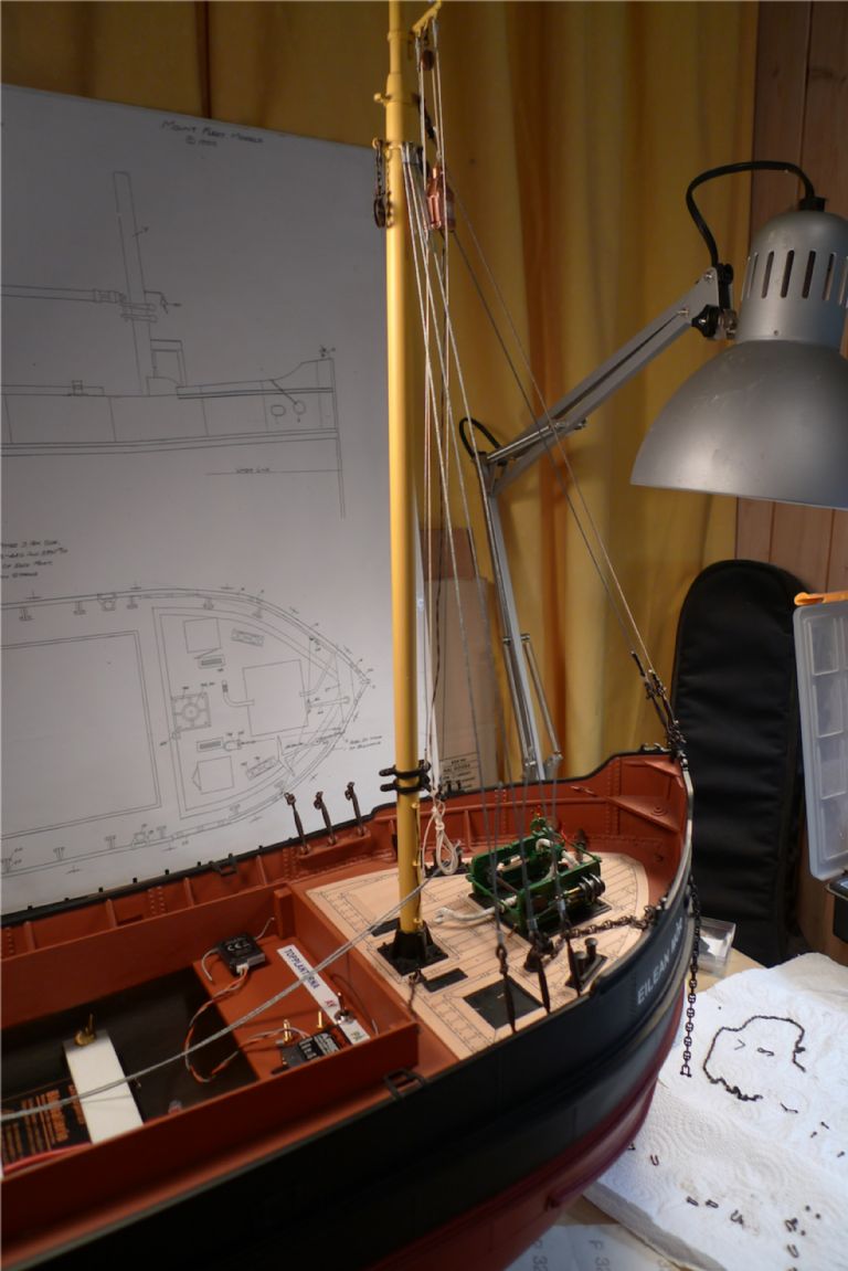
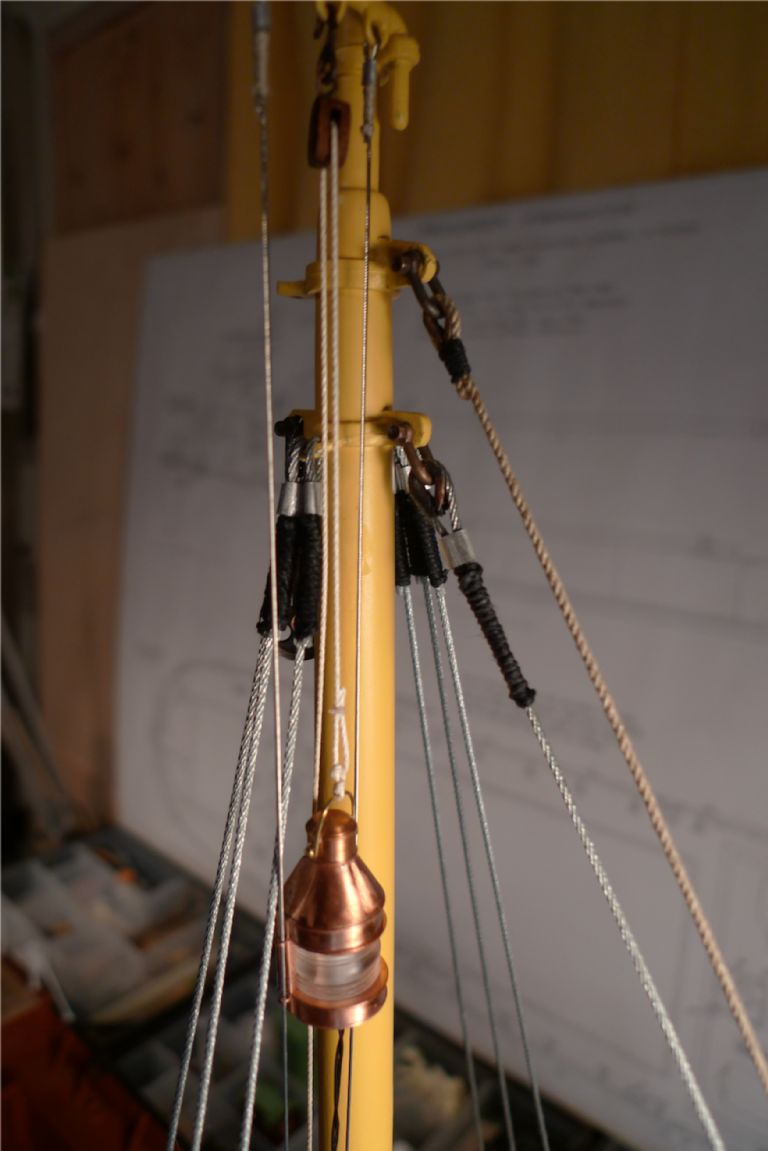
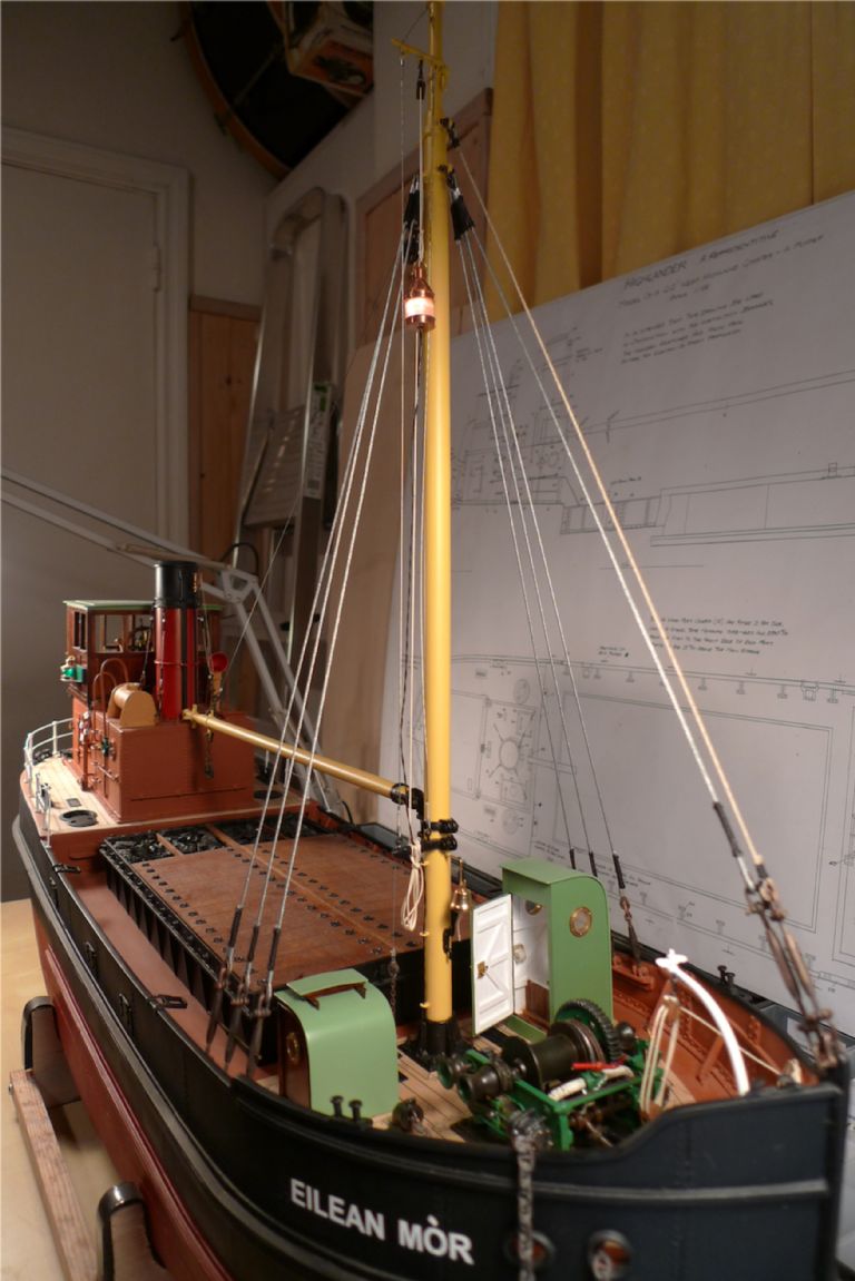
Participant@banjomanI began rigging proper by setting up the two forestays, one from 1 mm steel wire and the other from 1.1 mm rope. I initially tried using 0.8 mm steel wire for the second, but found that it became quite tricky to tension them evenly without putting a bend into the top of the mast, whereas the higher elasticity of the rope made the equal tensioning quite easy to achieve.
I also think that it looks rather nice with the two, contrasting materials next to each other.
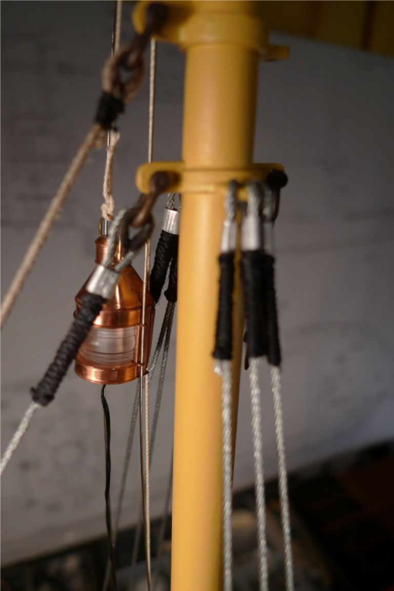
At this stage I also replaced the rigging for flying the top light, with steel wire runners instead of rope, and with a pulley block stropped with soft brass wire rather than with rigging thread.
As usual everything was served with rigging thread at the ends.
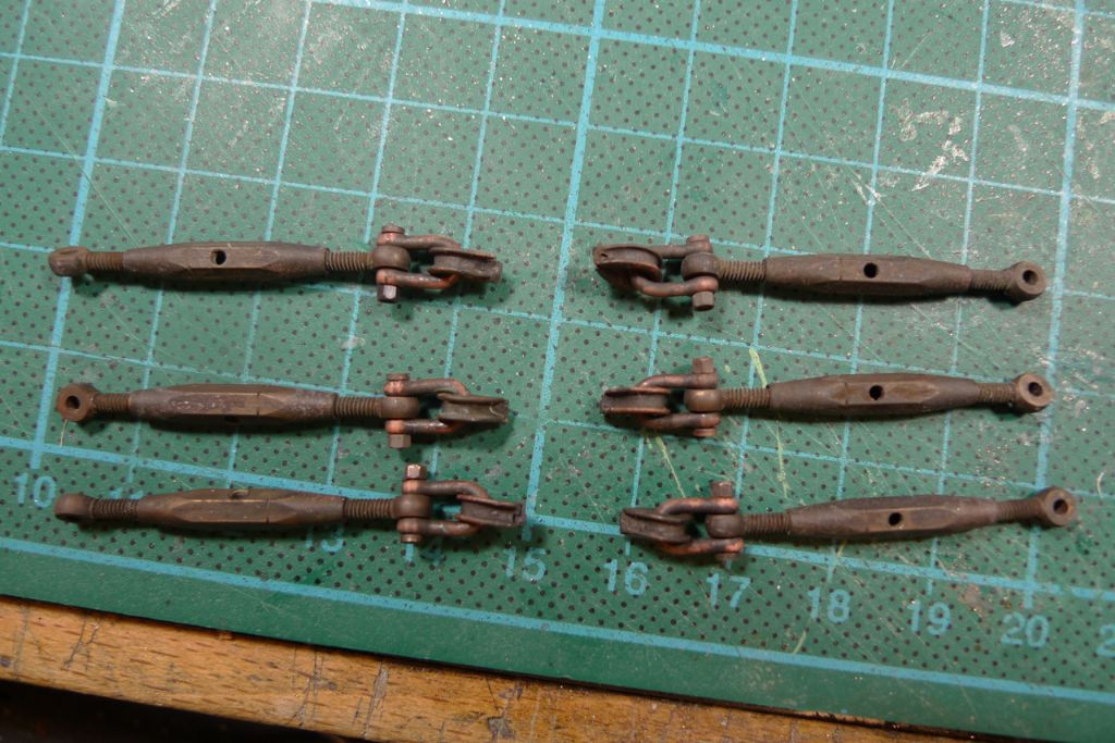
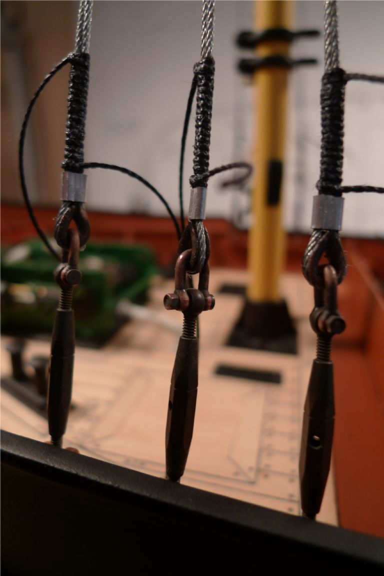
Next the bottlescrews for the shrouds were set up with shackles and thimbles …
… and attached to the chains with M1.6 nuts and bolts (tightening those six nuts was actually one of the most trying jobs of the whole build, given the very tight space available to work in).
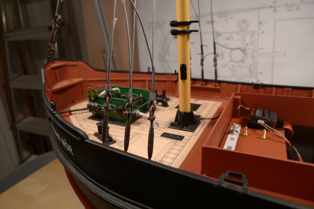
The shrouds were set up, first on the starboard …
… and then on the port side …
… and the endings again served with rigging thread. All such servings, and in general all permanent knots, were further secured by a liberal applications of watered down PVA glue, which dries totally invisible and very effectively stops things from becoming undone.
Given the pulling strength of real wire, I had perhaps better replaced the fastenings at the hounds band with something stronger than white metal, but I think (and hope!) it will hold even if there is a slight downwards bend where the shrouds are made fast …
With the stays and shrouds in place, the mast of course could be considered permanently fixed (although it can still easily enough be taken out of the ship if needed by simply unscrewing the bottlescrews to release the standing rigging) and the wiring for the top light …
… could be led through the thin pipes at the base of the mast …
… and connected up so that there were light at the top!

To be continued …
/Mattias
Edited By Banjoman on 14/12/2014 17:35:11
14 December 2014 at 18:01 #54344Bob Abell 2
Participant@bobabell2Nice rigging, Matt
Suppose you've had plenty of practice……..With your banjo?
Only pulling your leg
Your rigging is splendid and very business like!
Are you adding the crew?
Bob
14 December 2014 at 21:09 #54350Banjoman
Participant@banjomanOh no, Bob – rigging my banjo is nothing at all like this: it has four strings, dontcha know, whereas the shrouds are only three to a side. No resemblance whatsoever. Now, had I been a balalaika player, it'd have been a completely different tune …

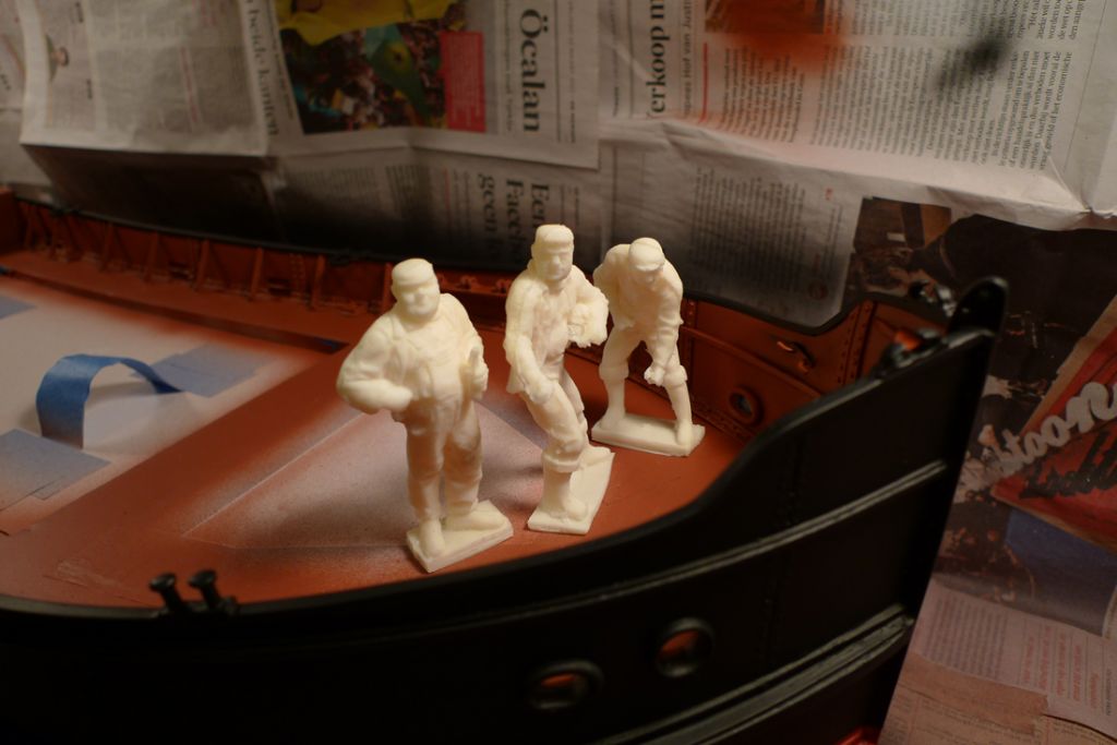
And yes, I'm certainly planning to include the three cast resin crew members that came with the kit; that is, unless I make a complete mess of cleaning up and painting them, which I hope won't be the case, although figure painting of any kind is summat I haven't done since I was a wee bairn splashing Humbrols (rather indiscriminately, if memeory serves me) onto Airfix Spitfire pilots and suchlike …
But speaking of the crew members, the kit, as already mentioned, came with three. From my reading up on Puffers, this should be realistic enough, as it seems they commonly had a crew of four: skipper, engineer, mate and deckhand. The engineer could be out of sight, down in the engine room, in which case three hands around the deck should be just right.
Anyway, I've decided that the bloke who just stands around with a bottle in his hand must be the skipper, as he can allow himself to skivvy off like that; furthermore, that bottle would of course have to contain something, and seeing that the skipper is rogue enough to set his crew to pinch coal from the cargo, I dare say he would not necessarily be wary of mixing alcohol and work at sea either, so it ought to be a beer bottle.
Some research on the Internet threw up a rather nice label for Aitkens 90/- Ale, which I've found out was a common enough brew in Scotland in the 1950s, not least in Glasgow (it was brewed in Falkirk, some 25 miles or so away) where I know from period photo evidence that it was advertised on trams.
The label has the further advantage of being graphically both simple and distinct, and I will thus have at least a go at reproducing it on the bottle:
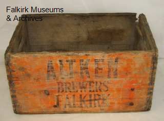
Furthermore, I've thought that another nice little detail to include somewhere around the deck would be an empty beer crate (for example with the loose battening wedges thrown into it) and if the skipper is partial to Aitken's beers, well an Aitken crate would be just the thing, wouldn't it?! And on the Falkirk museum website, I found a photo of a c. 1960 Aitken's crate, that will do just nicely as a prototype.
As it is part of their online catalogue, they even give the exact measurements, which will make reproducing one to scale that little bit easier.
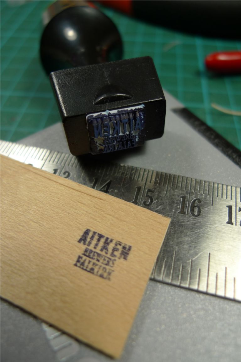
I haven't yet gotten down to actually making the crate, but I've tested a few ideas and techniques, including getting a rubber stamp made to order with as exact a reproduction to scale of the crate logotype that I was able to produce in the computer.
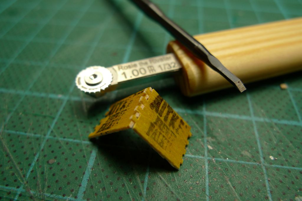
The trickiest part is probably going to be the mortice-and-tenon corner joints, as they would have to be +/- 0.5 mm each to be true to scale. I think that I will most likely cheat a little here, and instead make them 1 mm each; it will still look like a mortice-and-tenon job, but a little easier to cut out as I happen to have both a 1 mm-stepped "Rosie the Riveter" spur wheel (to help me measure it out on the wood) and a 1 mm chisel.
Below is a rough trial piece with the 1 mm mortices and tenons, and with too short sides; still, I'd say that the approach seems alright in principle …
To be continued …
/Mattias
Edited By Banjoman on 14/12/2014 21:10:24
Edited By Banjoman on 14/12/2014 21:13:42
Edited By Banjoman on 14/12/2014 21:15:05
Edited By Banjoman on 14/12/2014 21:15:47
-
AuthorPosts
- Please log in to reply to this topic. Registering is free and easy using the links on the menu at the top of this page.
Code of conduct | Forum Help/FAQs
Latest Replies
Home › Forums › Building Kits › Topics
-
- Topic
- Voices
- Posts
- Last Post
-
-
Fairey Huntsman 31
1
2
…
5
6
Started by:
 Chris Fellows
in: Build Blogs
- 14
- 139
-
12 hours, 24 minutes ago
 Chris Fellows
-
Fairey Faun
1
2
3
Started by:
 Chris Fellows
in: Build Blogs
- 7
- 58
-
12 hours, 46 minutes ago
 Chris Fellows
-
Vic Smeed’s Silver Mist
1
2
…
32
33
Started by:
Bob Abell 2 in: Scratch build
- 4
- 822
-
13 hours, 25 minutes ago
 Tony Hadley
-
Fairey Huntsman 28
1
2
…
7
8
Started by:
 Chris Fellows
in: Build Blogs
- 1
- 195
-
14 hours, 54 minutes ago
 Chris Fellows
-
Eezebilt RAF Fire Boat
Started by:
Tim Cooper in: Build Blogs
- 2
- 3
-
15 hours, 29 minutes ago
 Dave Reed
-
Feathered Friends
Started by:
 Chris Fellows
in: Soapbox
- 3
- 7
-
18 hours, 36 minutes ago
 Chris Fellows
-
4D Modelshop
Started by:
Keith Long in: Scratch build
- 6
- 7
-
19 hours, 4 minutes ago
 Chris Fellows
-
John Cobb’s Crusader
1
2
…
7
8
Started by:
 Paul T
in: Scratch build
- 1
- 192
-
1 day, 14 hours ago
 John W E
-
Complex Automata
Started by:
 Colin Bishop
in: Soapbox
- 1
- 1
-
2 days, 17 hours ago
 Colin Bishop
-
RAF Fireboat ID
Started by:
 Dave Reed
in: Collectors’ corner
- 8
- 24
-
3 days, 18 hours ago
Tim Cooper
-
TID steam tug 42″ – PN Thomas drawing enlarged
1
2
Started by:
 Ray Wood 3
in: Scratch build
- 8
- 33
-
4 days, 12 hours ago
 Richard Simpson
-
Lady of Skye (puffer)
1
2
Started by:
 mick east
in: Build Blogs
- 9
- 43
-
4 days, 22 hours ago
 Richard Simpson
-
Building a hull.
Started by:
 mick east
in: Scratch build
- 7
- 10
-
6 days, 21 hours ago
 Ray Wood 3
-
Todays Boating
1
2
…
210
211
Started by:
 ashley needham
in: All things floating
- 84
- 5,252
-
1 week ago
 Colin Bishop
-
Sea Rover Restoration
Started by:
harry smith 1 in: Collectors’ corner
- 4
- 10
-
1 week ago
 Richard Simpson
-
WORKSHOP LIGHTING
Started by:
 John W E
in: All things floating
- 9
- 18
-
1 week, 1 day ago
 Colin Bishop
-
Mayhem Website Down
Started by:
 Colin Bishop
in: All things floating
- 4
- 10
-
1 week, 4 days ago
 Colin Bishop
-
MAGGIE M trawler
Started by:
 sammyk
in: Buy/Sell or Trade
- 2
- 3
-
1 week, 4 days ago
 sammyk
-
meter
Started by:
 Alasdair Allan
in: All things floating
- 5
- 16
-
1 week, 6 days ago
 Chris Fellows
-
River Queen 2”- 1’.
Started by:
Richard B in: Steam powered models
- 5
- 7
-
2 weeks ago
Richard B
-
Deluxe Superphatic Glue.
Started by:
 Colin Bishop
in: All things floating
- 4
- 12
-
2 weeks ago
 Chris Fellows
-
How to add photos to your posts
Started by:
 Colin Bishop
in: Adding Images to Forum Posts
- 3
- 16
-
2 weeks ago
Len Morris 2
-
Cataract
Started by:
Bob Wilson in: Soapbox
- 2
- 4
-
2 weeks, 1 day ago
 Colin Bishop
-
The mighty tug Wattle
1
2
3
Started by:
 mick east
in: Build Blogs
- 10
- 61
-
2 weeks, 1 day ago
 Richard Simpson
-
Clyde Puffer Glenaray
1
2
3
Started by:
 Alasdair Allan
in: Build Blogs
- 6
- 57
-
2 weeks, 4 days ago
 Alasdair Allan
-
Fairey Huntsman 31
1
2
…
5
6
-


