The world's leading magazine for all model boating interests
Moonbeam
Moonbeam
Home › Forums › Sailing Models › Moonbeam
- This topic is empty.
-
AuthorPosts
-
25 April 2016 at 09:07 #64894
Banjoman
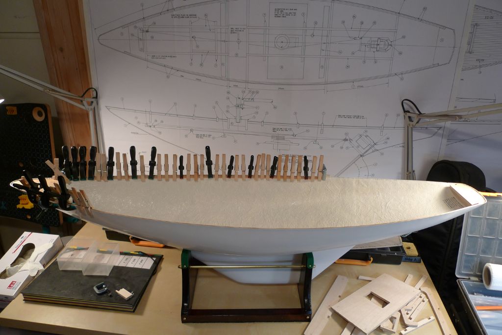
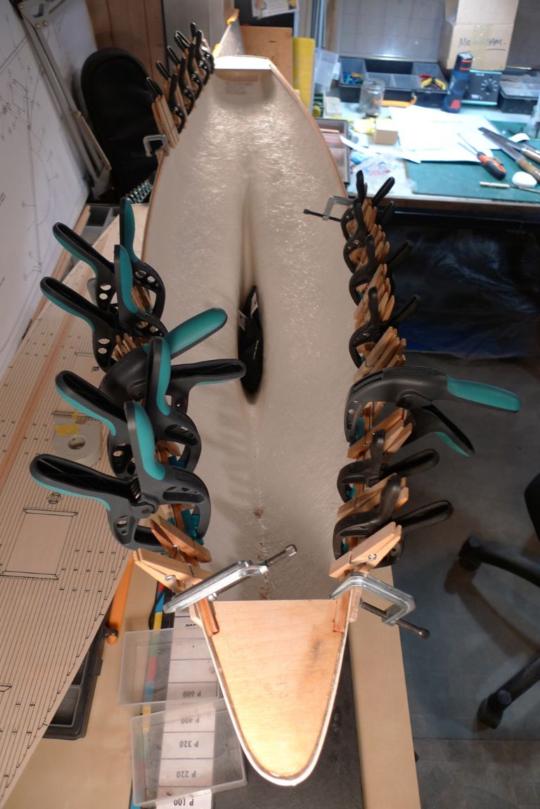
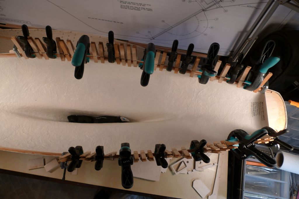
Participant@banjomanBuild progress has been rather slow of late, as spare time all of a sudden seems to have taken on a certain hen's teeth quality. When not gallivanting off to Chatham, though, or unblocking drains, or yet other stuff, I've at least managed to finish glueing in the edge strips …
… a couple of strips at a time …
…
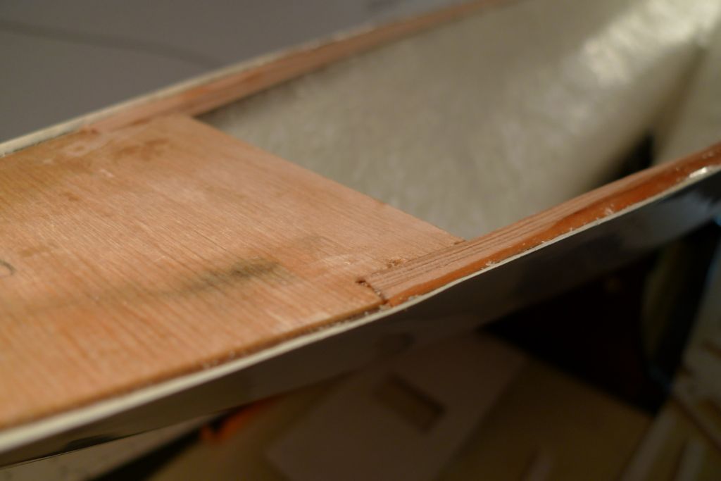
… until a double layer of 6×3 mm strips were solidly in place.
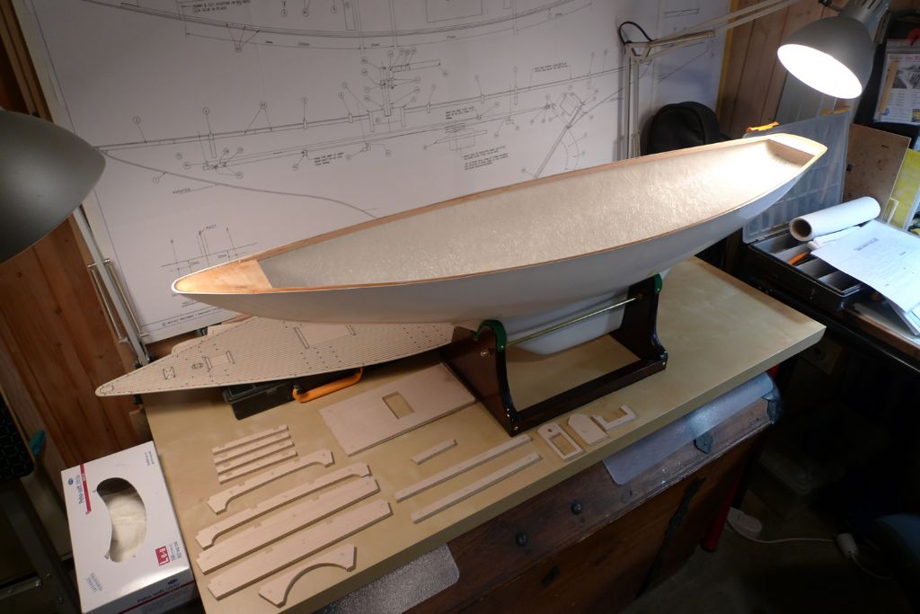
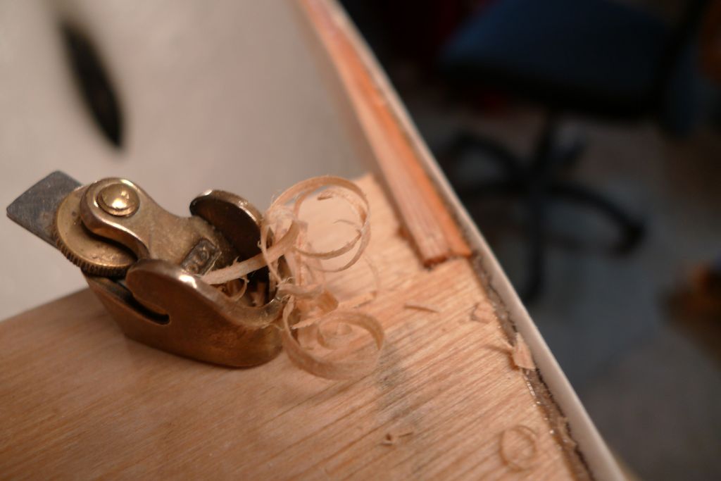
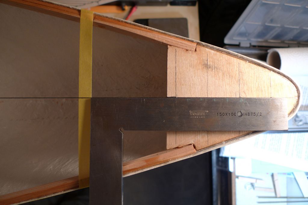
Again, the luthier's plane came in handy for the first, rough …
… blending in of the strip ends with the bow and stern pieces; once the deck beams are in, and can be taken into account, I will finish these blendings properly.
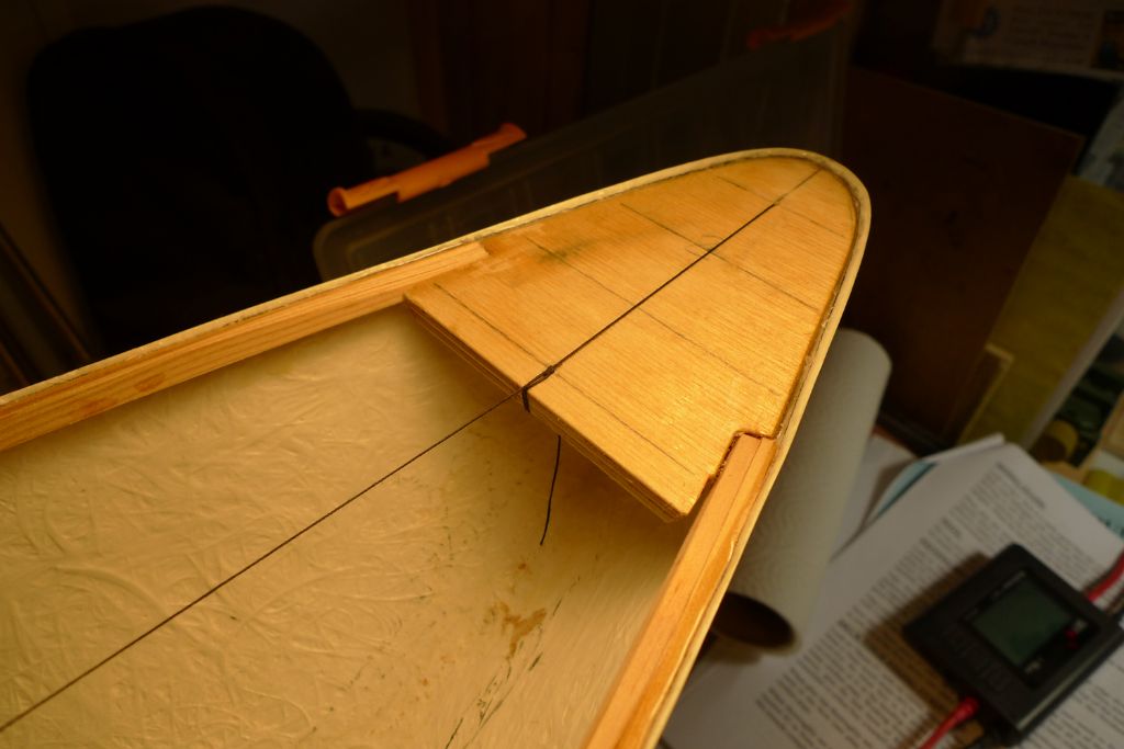
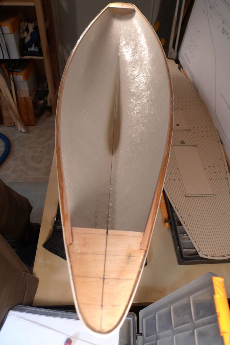
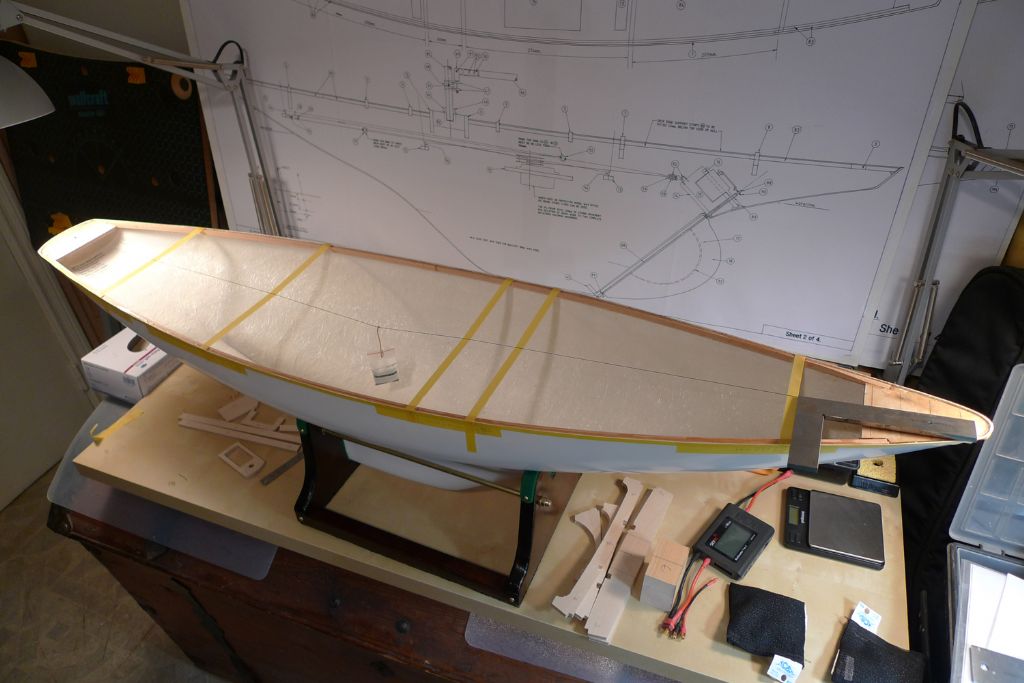
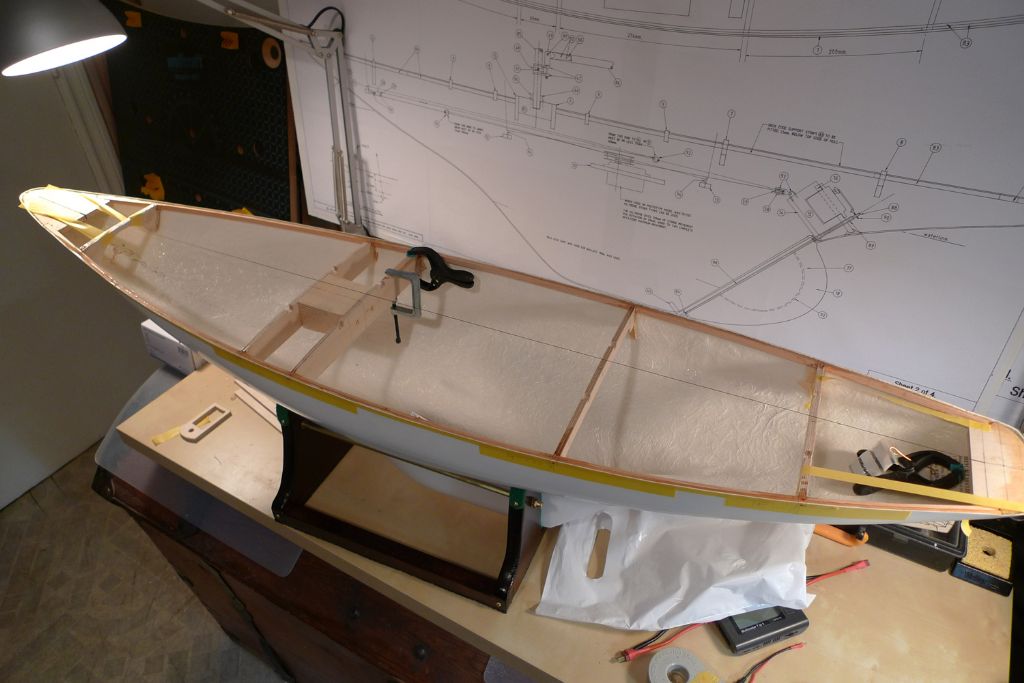
In the meanwhile, I've begun preparing for the deck beams; first, by establishing a temporary centre line in the form of a thread stretched between the carefully measured centre lines of the the bow and stern pieces …
… to provide a plumb line against which hull symmetry and beam centricity can be checked.
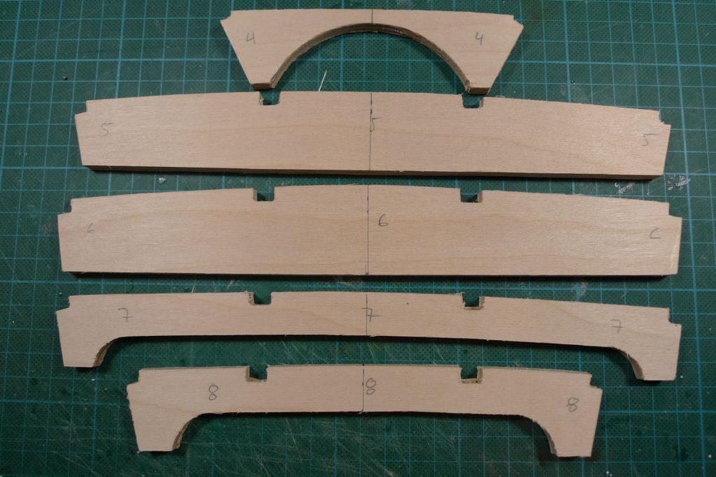
To this end, I also drew in the centre lines on the deck beams themselves.
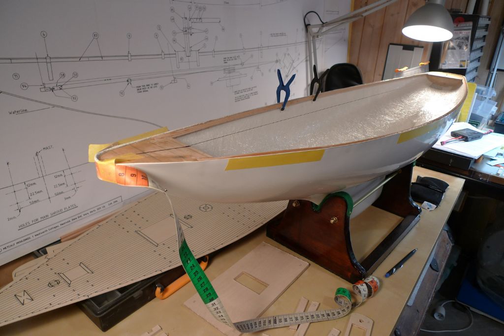
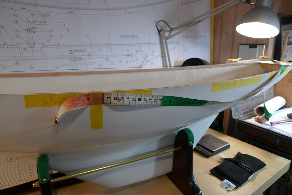
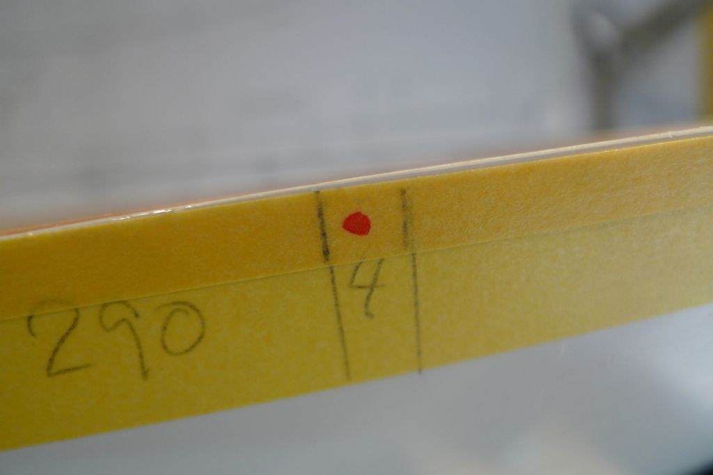
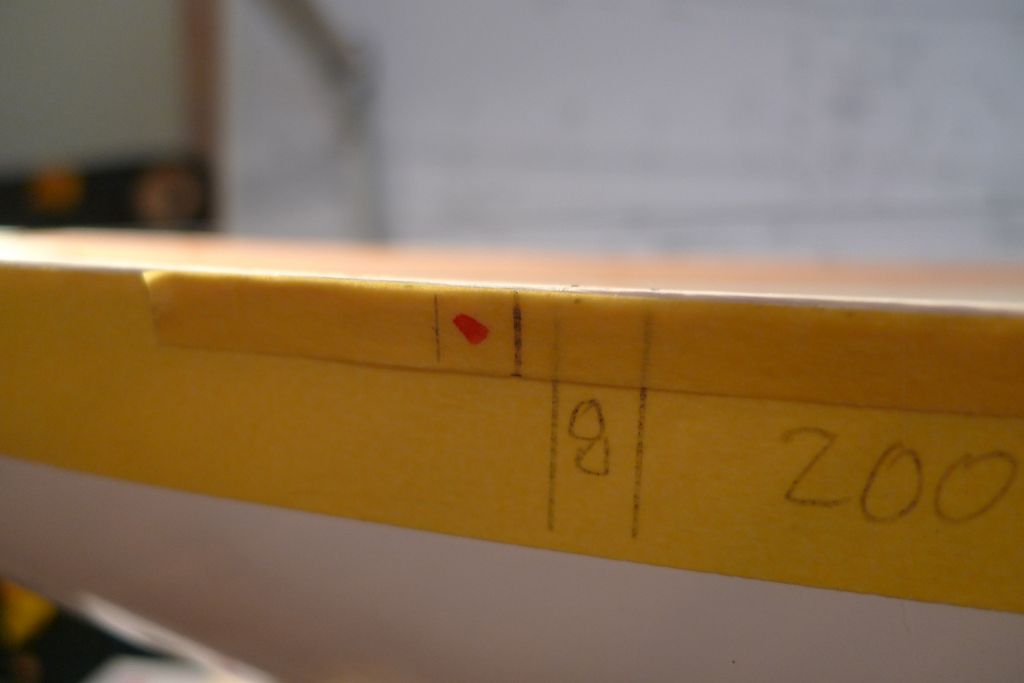
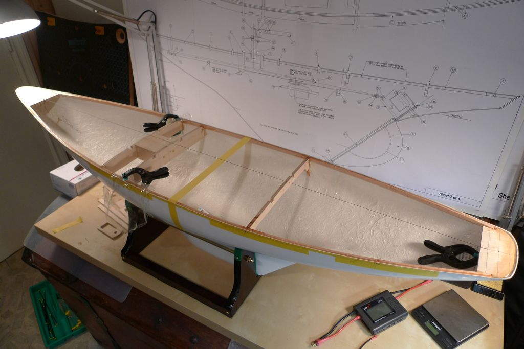
Next, I applied masking tape to relevant parts of the port and starboard sides of the hull, and with a tape measure …
… found and markd out the locations for the deck beams accoring to the measurements given on the plan. The instructions say the beams may be installed with a margin of error of a few millimeters aft or forrard, but this still requires knowledge of the intended positions.
To be continued …
/Mattias
Edited By Banjoman on 25/04/2016 09:08:07
Edited By Banjoman on 25/04/2016 09:08:46
10 May 2016 at 12:17 #65295Banjoman
Participant@banjomanBuild progress continues to be on the slow side, not least becuase of a recent, week-long holiday in the South of France; however, a few things have happened since my last posting …
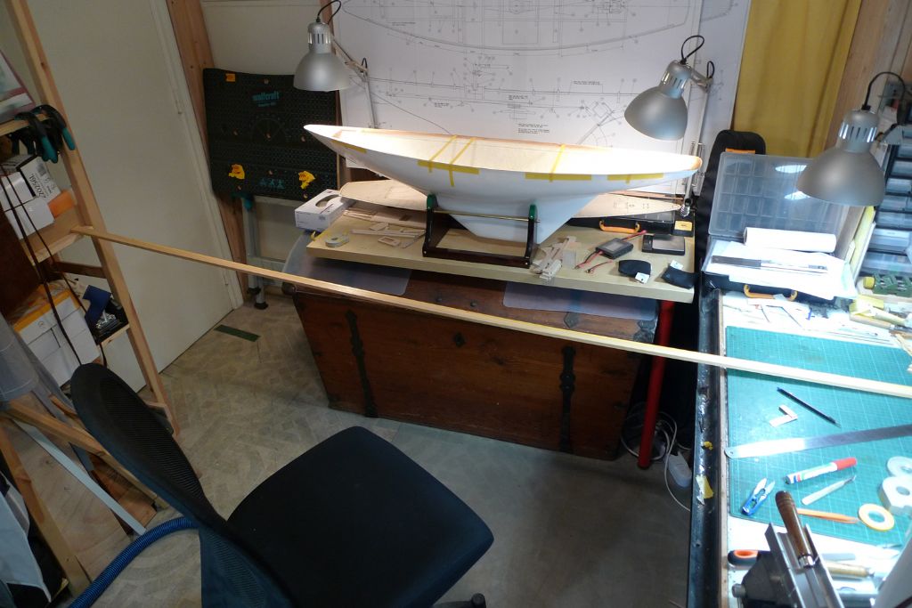
After checking the beam placements as previously measured, I came to the conclusion that they were probably not entirely correct. I therefore decided to further verify them by an alternative method, to which end a 2 metre plus strip of masking tape was attached to an even longer piece of wood, and all relevant measurements for both port and starboard sides marked out on it.
With the tape strip then applied alog the outside of the hull, this method confirmed that while some previous measurements were as close to identical as makes no difference …
… others were out by nigh on half an inch!
The new, potential beam placements were then marked out athwartships with more tape, and a series of angles and distances between various points on both sides of the hull …
… carefully measured to confirm that yes, I now had the stick by the enough of the right end to be able to proceed.
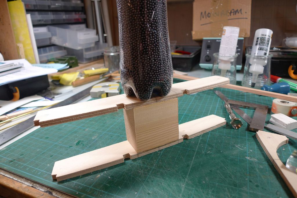
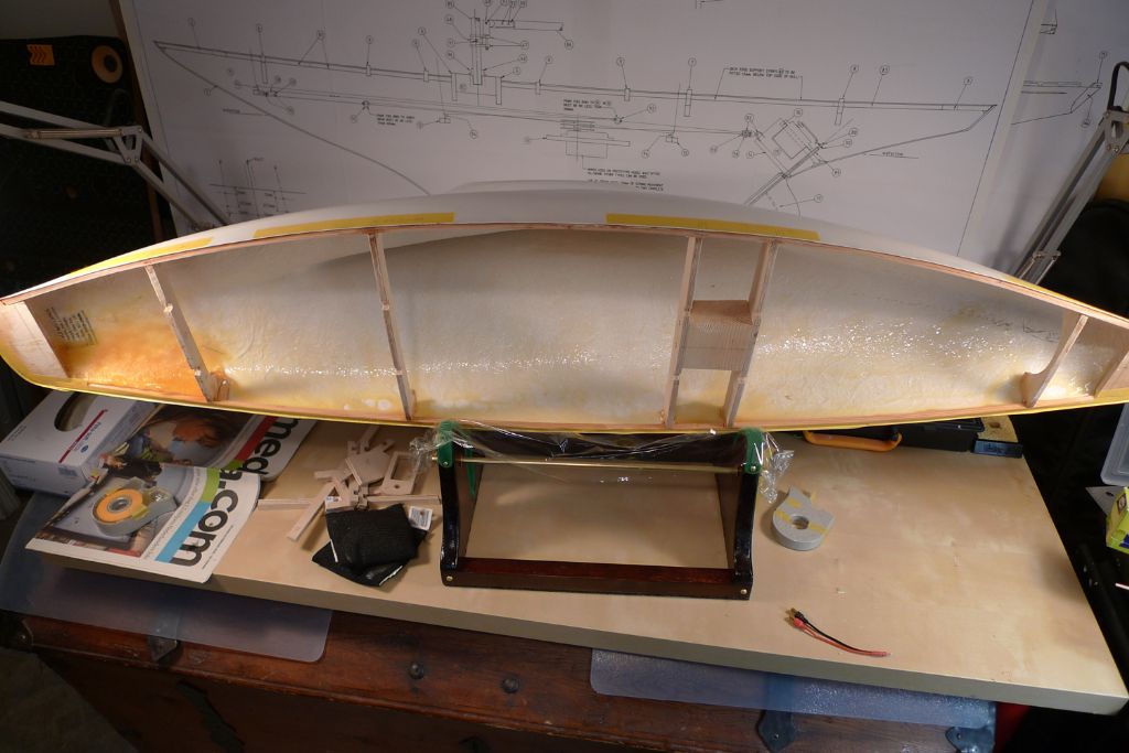
The two midships beams, and the mast support block were then offered up to their places and shaped to fit …
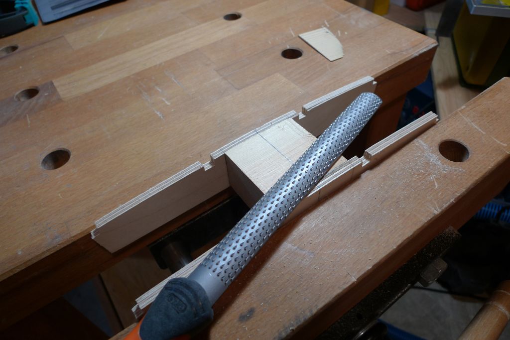
… including filing down the top of the block to follow the beam cambers …
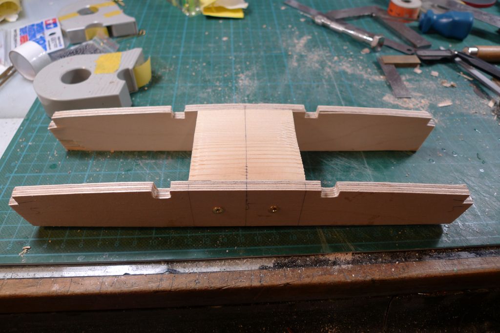
… and then glued together with 24 hour epoxy …
… and then gluied into the hull together with a further midshop deack beam.
To be continued …
/Mattias
Edited By Banjoman on 10/05/2016 12:19:31
Edited By Banjoman on 10/05/2016 12:21:02
11 May 2016 at 11:47 #65333Banjoman
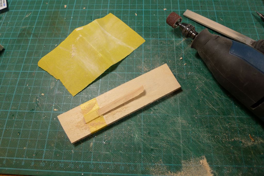
Participant@banjomanIn spite of trying the deck beams either side of the mast support block up against the hull before glueing the package together, I managed to get one beam end slightly out of true, so a short peice of 1 x 6 mm strip wood was sanded thin at one end …
… and glued on top of the starboard side of the beam in question; the fore- and aftmost beams were also fitted and glued in at this point.
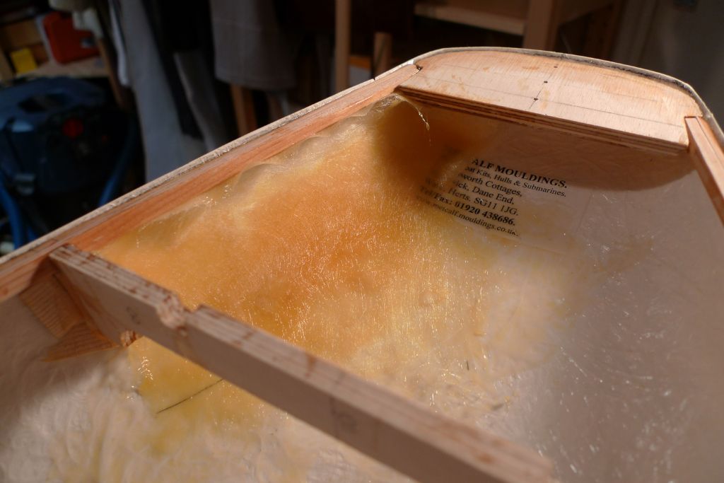
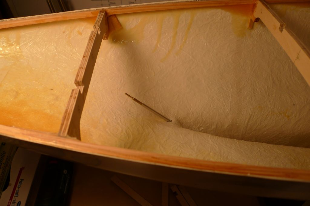
Next, the area in which I'd detected a potential crack in the hull was reinforced on the inside with some glass fibre cloth and finishing resin.
I also poured smaller quantities of finishing resin along the undersides of the deck support strips, to make sure of a perfectly sealed joint against the hull.
Next, although it is not yet time to fix them into place, the two fore-and-aft beams were offered up, and trimmed to size, at which point I realised that even reading the instructions through four times before starting a build is not sufficient insurance against general thick-headedness!
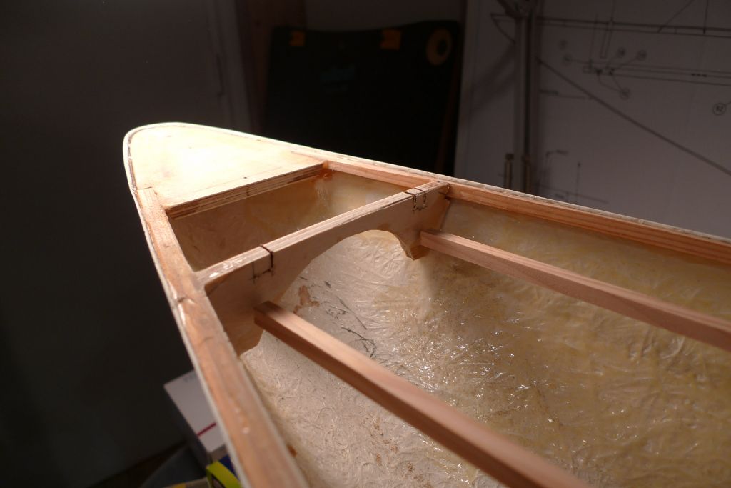
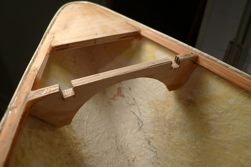
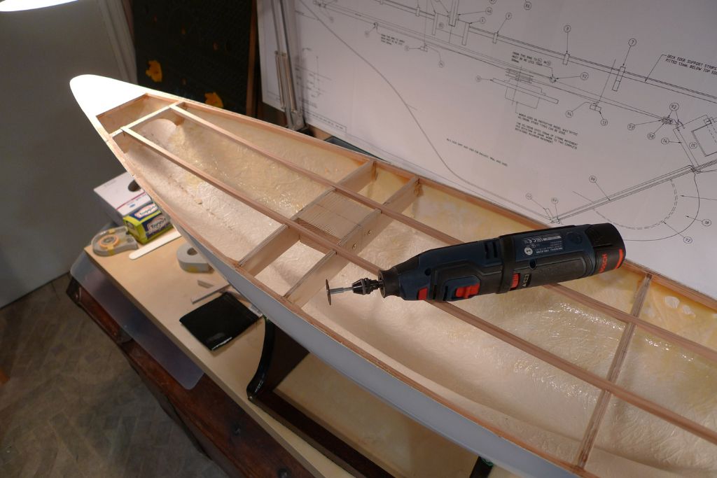
It turned out I had completely missed the instructions to measure for and cut out the recesses for the fore-and-aft beams in the foremost transversal beam. However, it was still easy enough to just chain drill the lower recess edges, and to cut down to there with a cutting disc in the rotary tool …
… after which the material surplus to requirement could be broken off by applying a very mild force with a pair of pliers.
These recesses as well as the pre-cut ones in the other beams were then filed down until all beam tops were flush with one another, after which the fore-and-aft beams were laid aside for the time being.
To be continued …
/Mattias
Edited By Banjoman on 11/05/2016 11:47:55
Edited By Banjoman on 11/05/2016 11:48:29
Edited By Banjoman on 11/05/2016 11:50:35
12 May 2016 at 09:03 #65346Banjoman
Participant@banjomanNext up, it was time to get started on the rudder assembly. This is made up from a brass rudder post and blade reinforcement, with the actual blade made up in the form of a styrene sheet sandwhich.
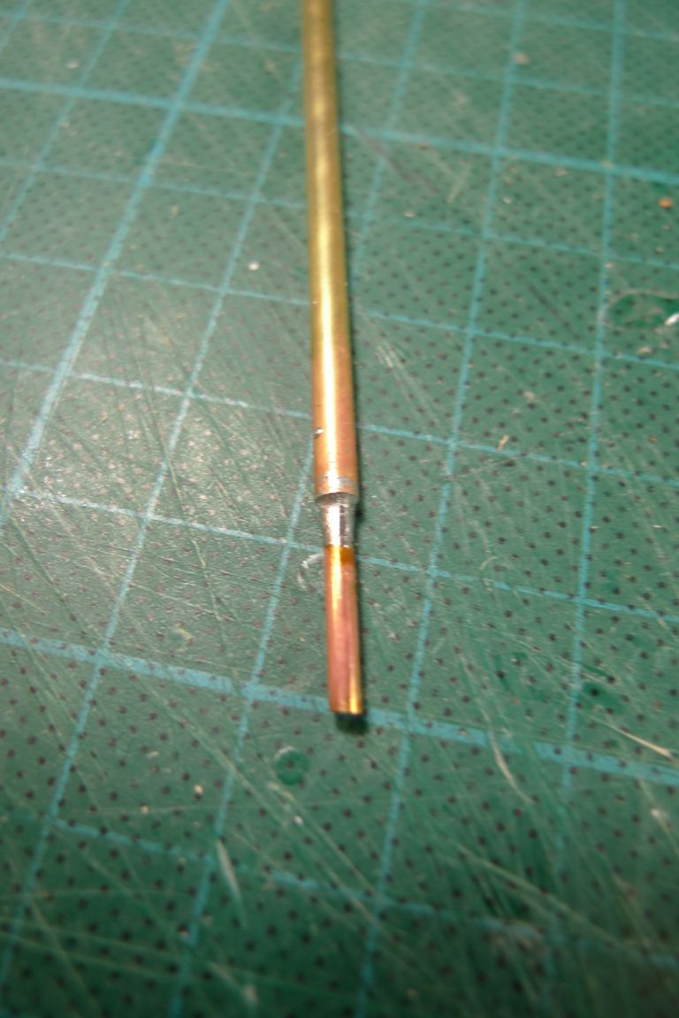
As the rudder post blank of 3 mm brass tube was a tad short of the measurements foreseen on the plan, I decided to add a short extension in the form of a shoprt length of 2 mm brass, inserted into the tube and soldered in place. It probably will not be needed, in which case the whole thing can easily be cut back as required, but if it does prove useful, it will be easier to have added it at this stage, when the application of heat is not an issue.
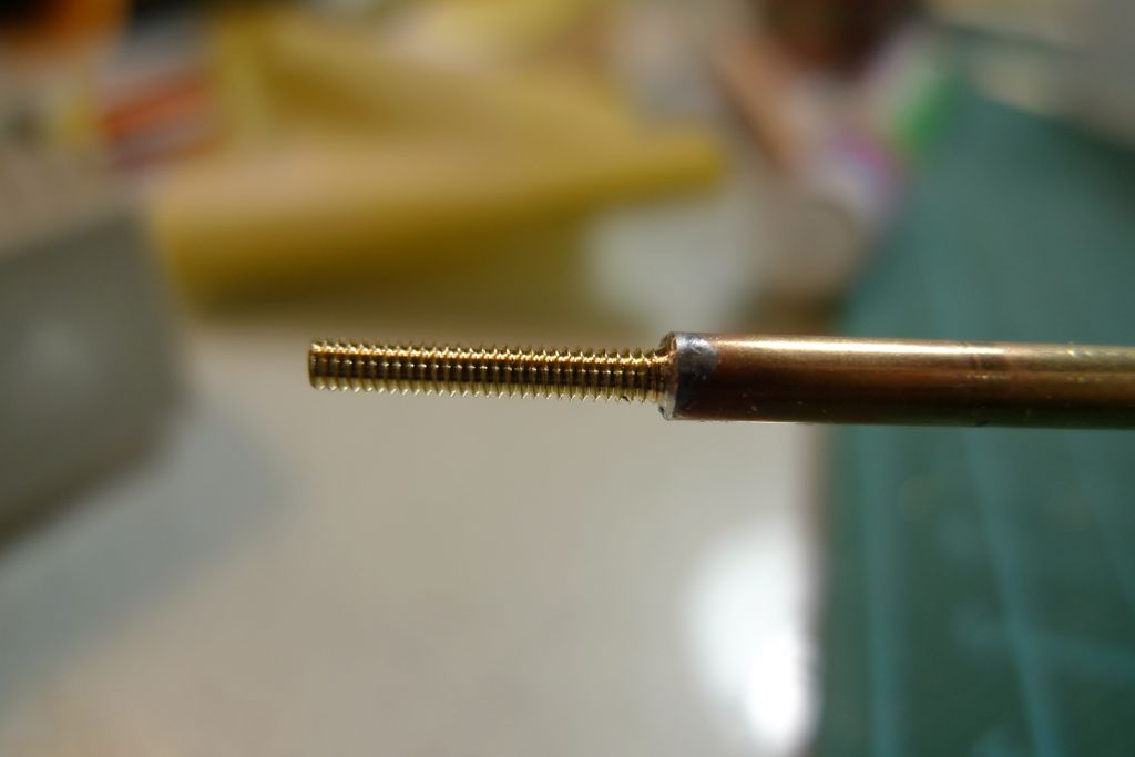
I also decided to cut a M2 thread on the extension.
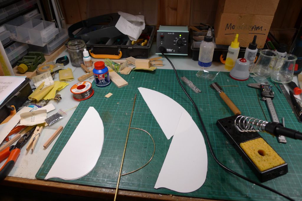
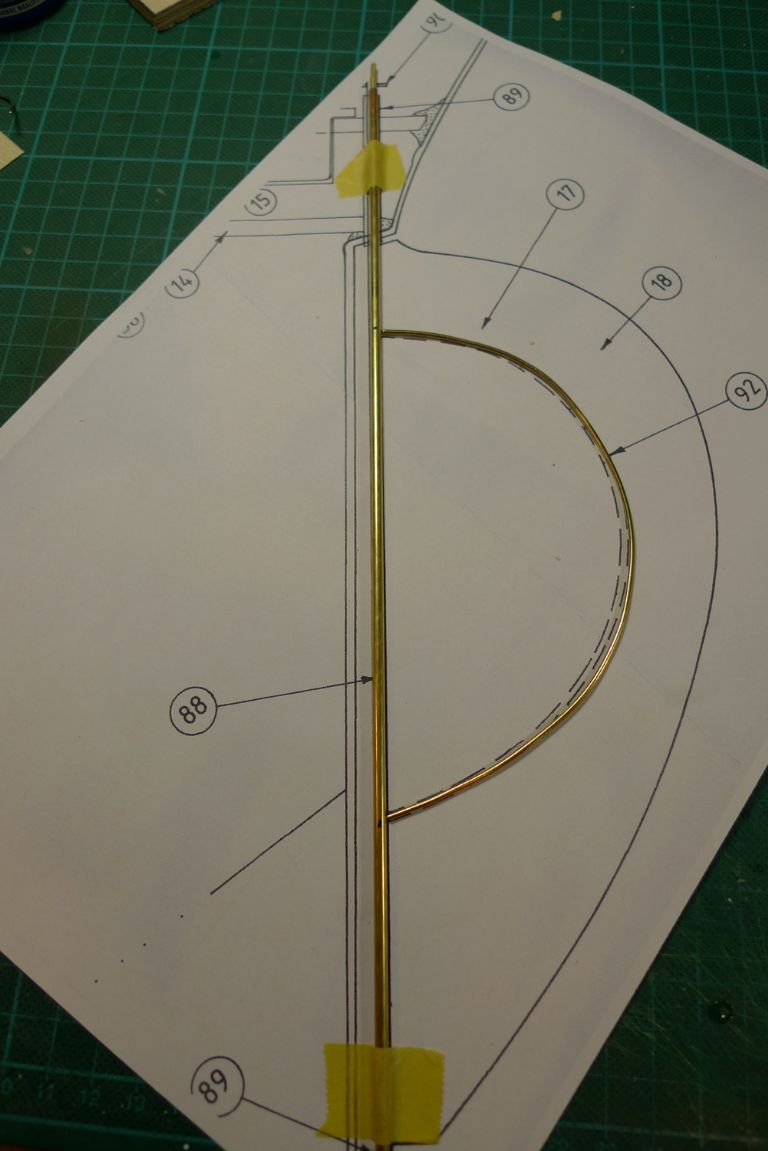
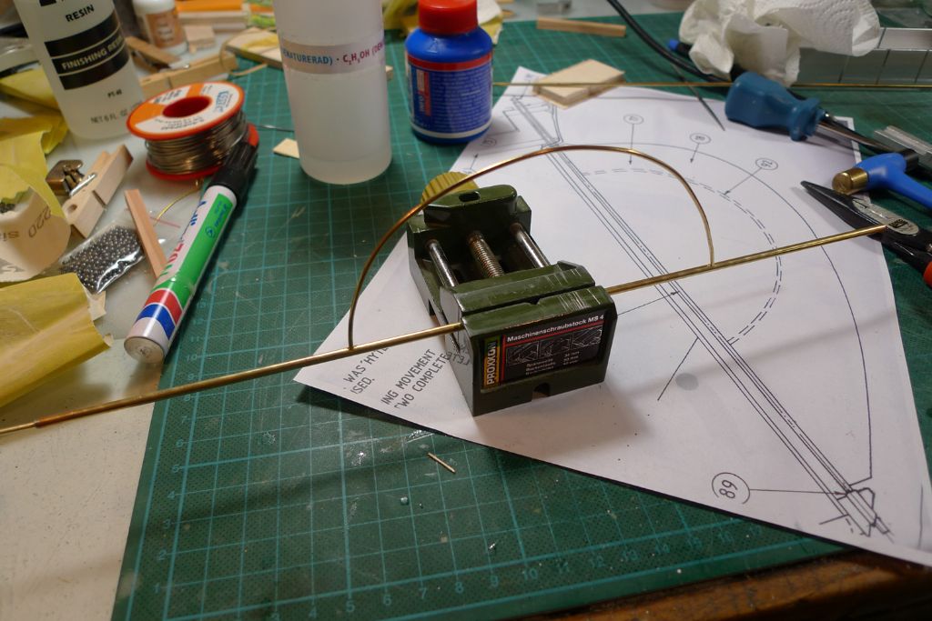
Next, the 1.5 mm brass rod blade reinforcement shape was checked against a photo copy of the relevant part of the plans, the spots were it touches the post marked out …
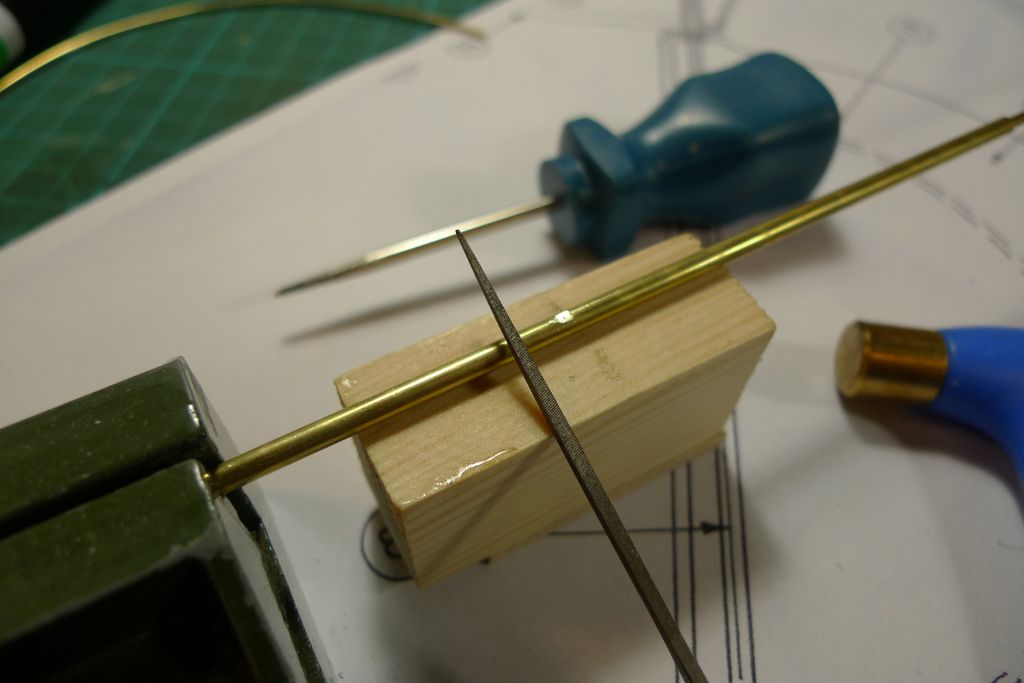
… filed flat, and given a light centre punch to aid the start of the drill …
… that was used to drill out holes in the post for the reinforcement rod to fit into.
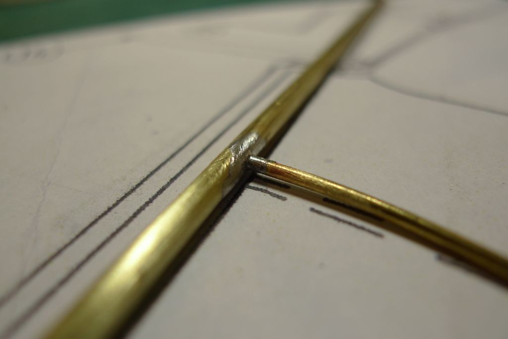
The reinforcement was then soldered in place …
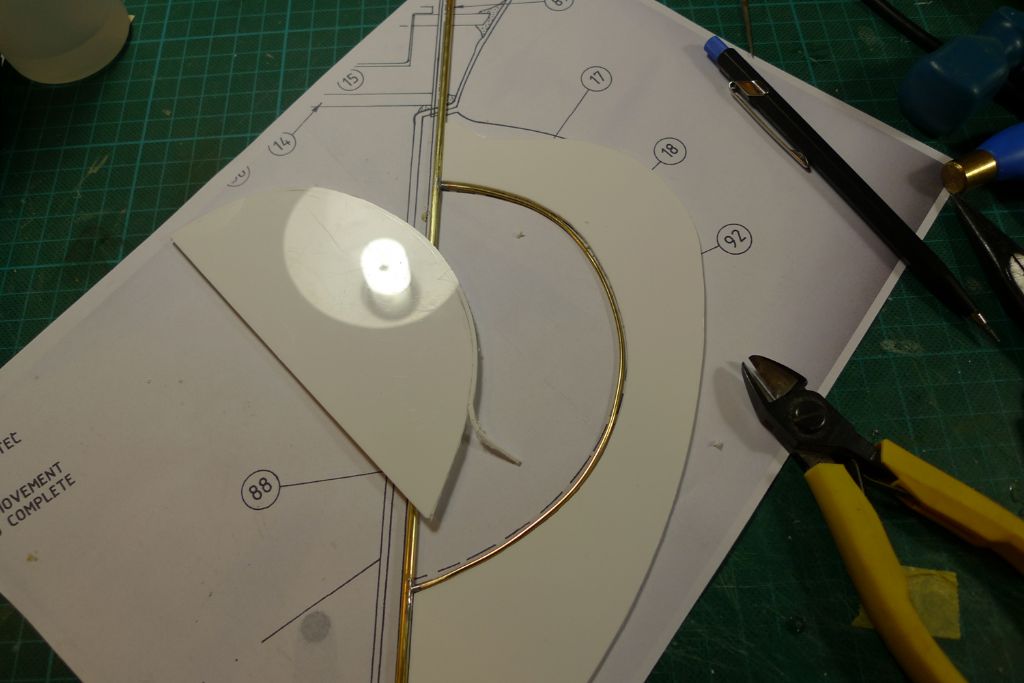
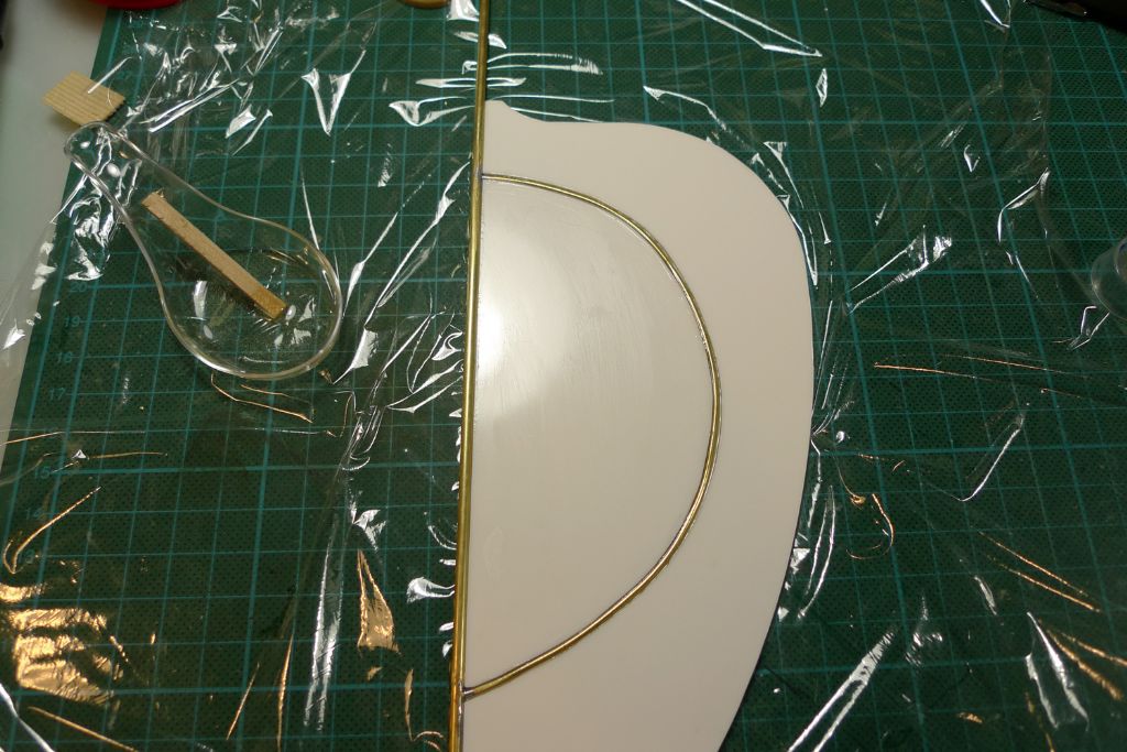
… and its curve copied onto the centre part of the styrene sandwhich, which was cut to make room for the brass rod to pass through it. The outer part was cut off on the bandsaw, after which the excess material was removed from the inner bit with a pair of fine side cutters.
Next, one of the two outer blade parts was glued together with the two center bits …
… and secured to the post and reinforcement using 24 hour epoxy. Once the epoxy has fully set, the second outer blade part can be glued in place, too, but that shall have to wait until sometime this weekend. The kitchen foil is of course there to insure against an accidental excess drop of epoxy on the underside that might otherwise glue the whole thing down to the cutting mat surface …
To be continued,
/Mattias
12 May 2016 at 09:22 #65347Bob Abell 2
Participant@bobabell212 May 2016 at 09:56 #65348Banjoman
Participant@banjomanBob,
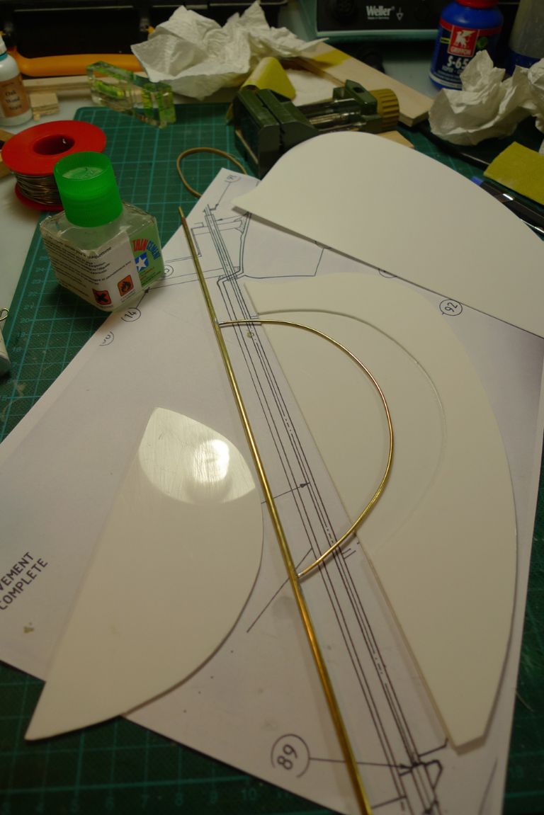
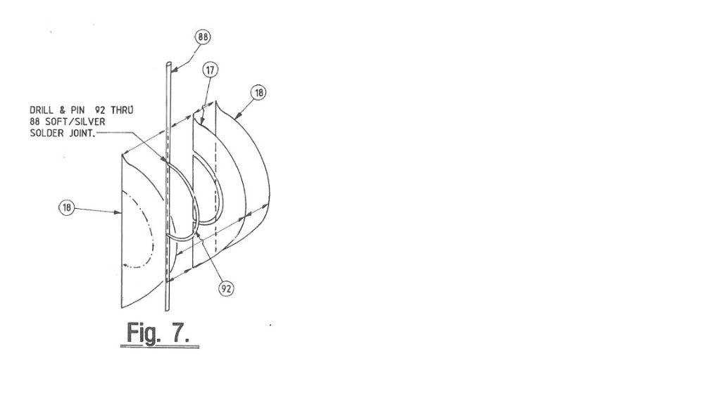
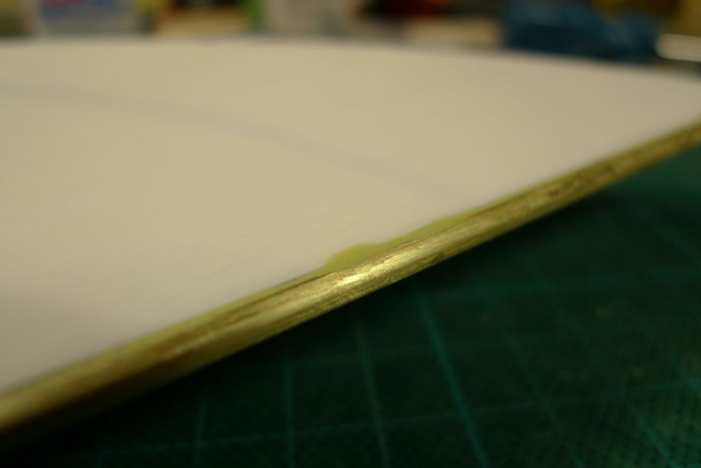
It is a triple decker sandwhich construction: in the centre is a 1.5 mm thick styrene blade, through which is cut a passagefor the reinforcement brass rod. This is the sandwhiched together with the two outer blade parts, which are from 1 mm thich styrene, like this:
Given that the styrene is not just stuck together but meltet/fused, using styrene glue, the result is actually quite strong.
It might still be worth considering straps for additional strength, although I don't really think it would be necessary; in any case, one would have to be rather careful, using sufficient heat sinks, when soldering them onto the rudder post, as this is now in permanent contact with the styrene, which of course has a rather low melting point.
The soldered joints bewteen the rudder post and the reinforcement ends are also stronger than I think they look, as the ends have drilled and pinned into the tube before soldering. However, as I just said, i shall indeed have a wee think about the possibility of adding a few straps for further strength …

/Mattias
17 May 2016 at 13:07 #65458Banjoman
Participant@banjomanAfter a weekend away with my banjo on my knee — at the annual Student Orchestra Festival in Sweden to be precise — I managed to get some more building in yesterday.
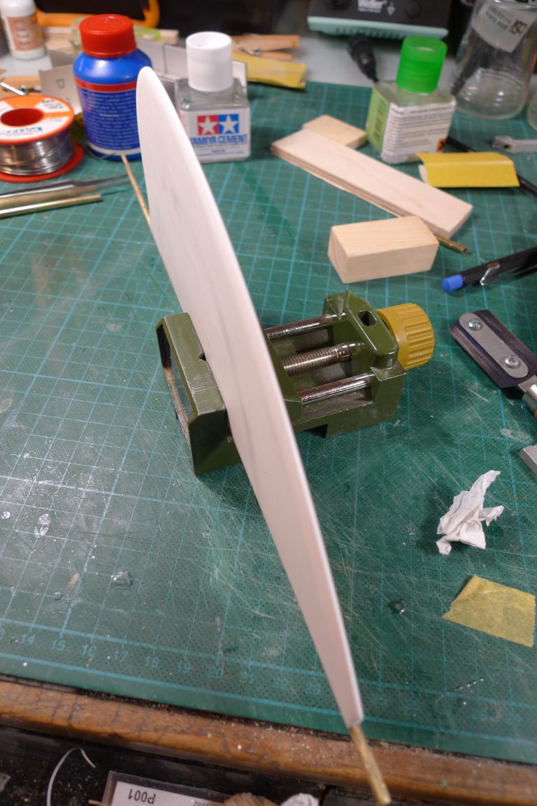
For starters, the third and final piece of styrene sheet was glued on with Tamiya cement to complete the rudder …
… the back edge of which was sanded down to create a more aerofoil (or should that be hydrofoil?) section.
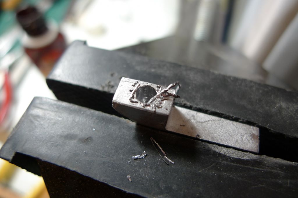
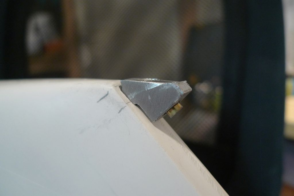
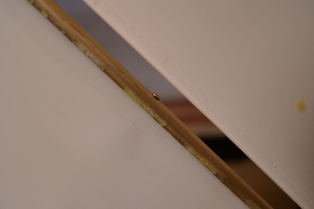
I also drilled and filed out the hole in the skeg to 4 mm diameter …
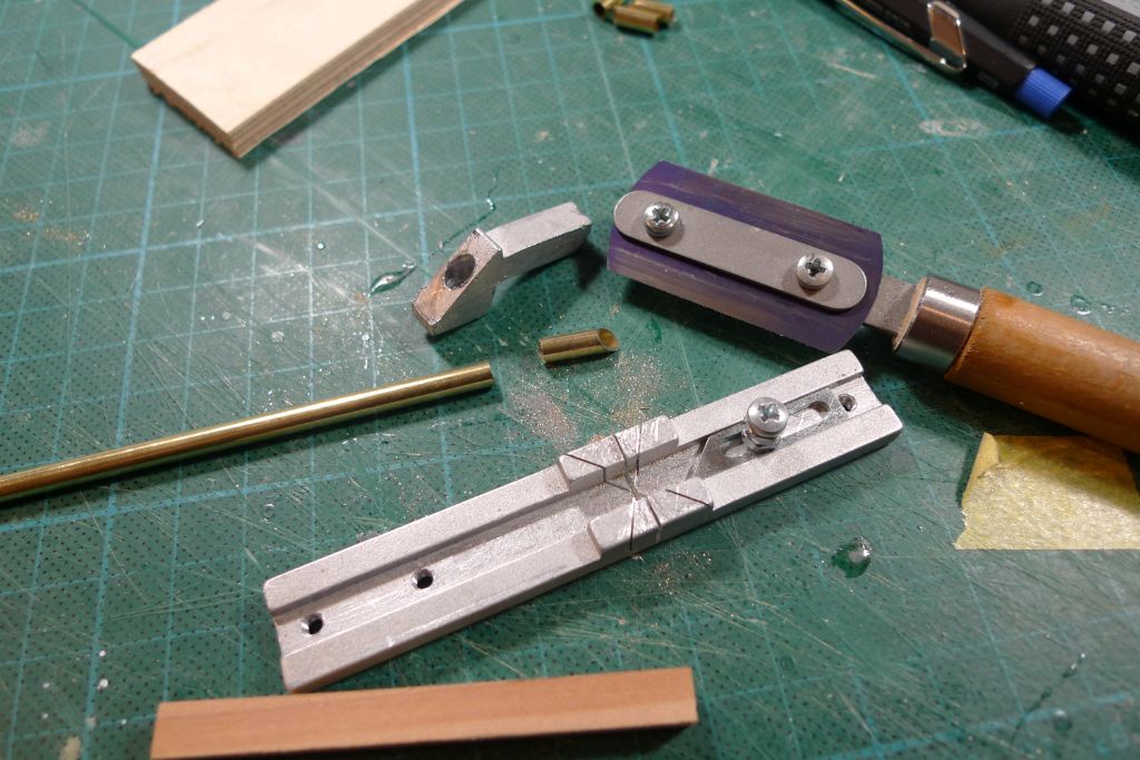
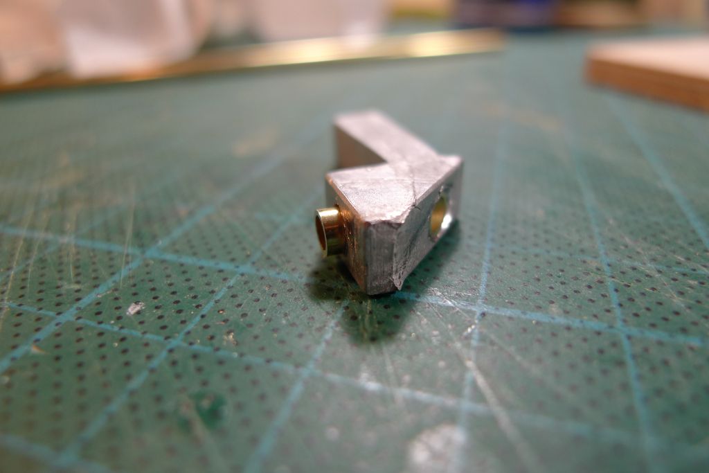
… cut off a suitably short piece of 4 mm brass tube, with one end at 45 degrees …
… and glued this into the skeg …
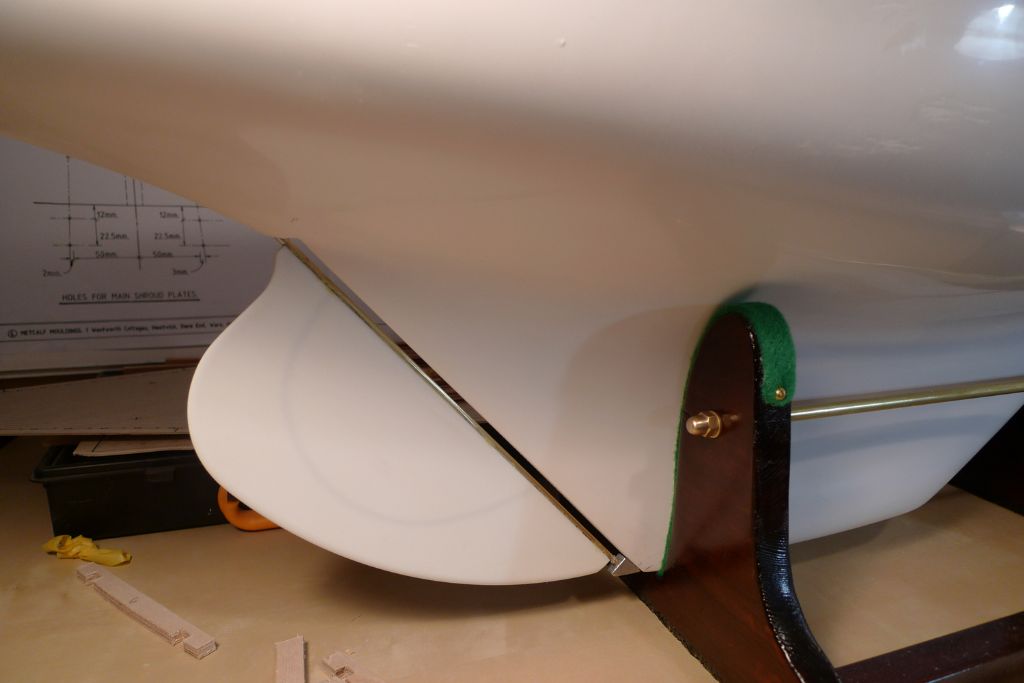
…thereby creating the lower pivot point for the rudder post.
Next, the keel was drilled through in a suitable spot …
… and the ensuing hole gradually opened up with a series of square section files …
…. to take the circa 5 x 5 mm tang.
For the time being, this is all just dryfitted, but after further working the inner face of the skeg …
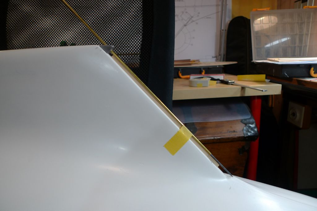
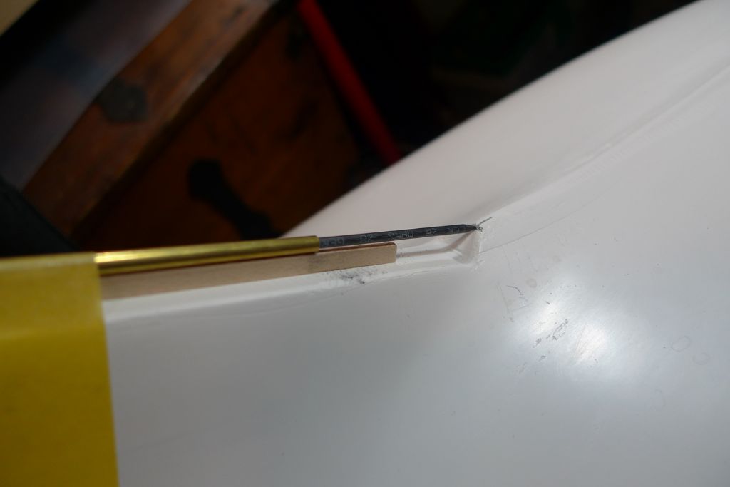
… to get a sufficiently good fit against the keel, a length of 3 mm brass tube was passed through the skeg, resting on a length of maple strip to ensure parallellity with the keel …
… and with a piece of lead inserted into the brass tube, the position was marked out …
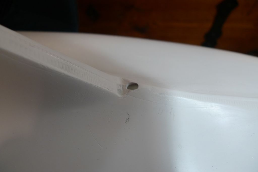
… for where the rudder post needs to traverse the hull, and a hole opened up to take a piece of 4 mm tubing at the correct angle.
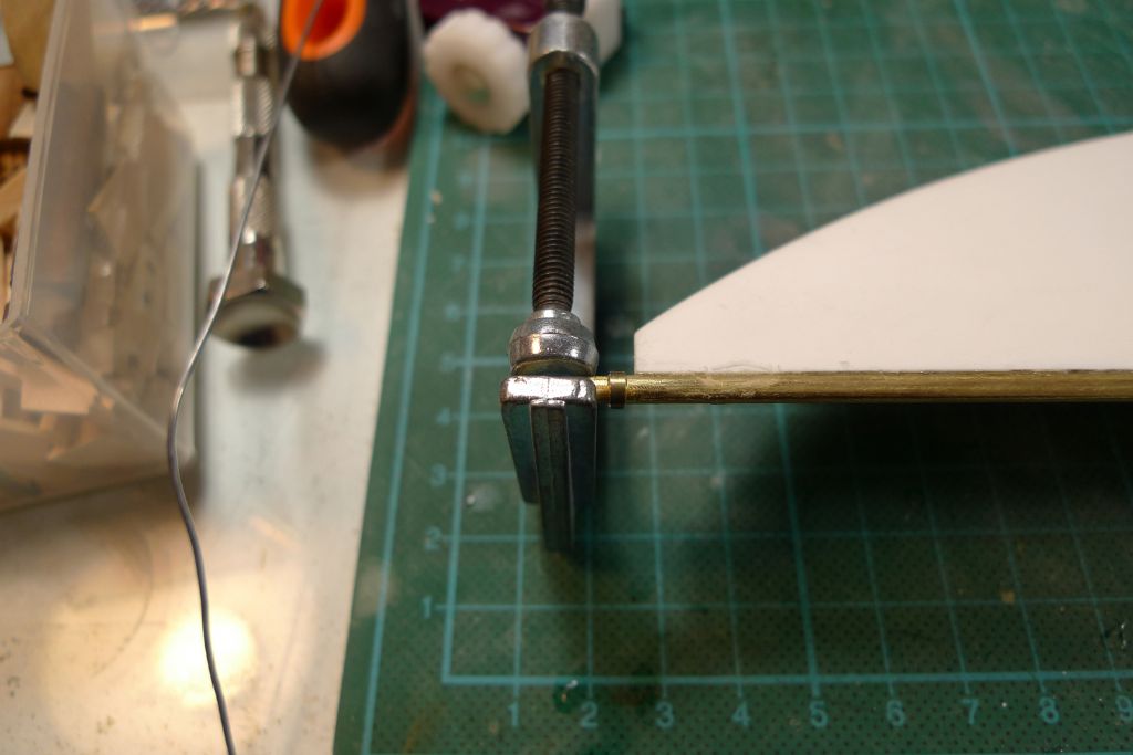
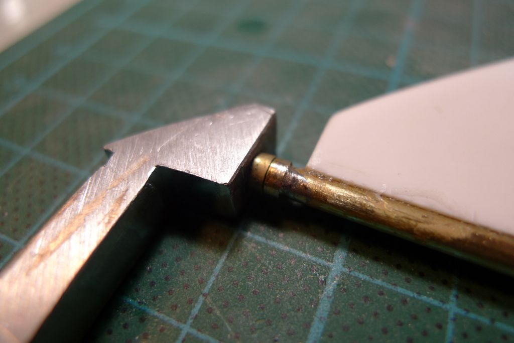
A 1.5 mm wide ring of 4 mm tube was also cut, and slid over the lower end of the rudder post …
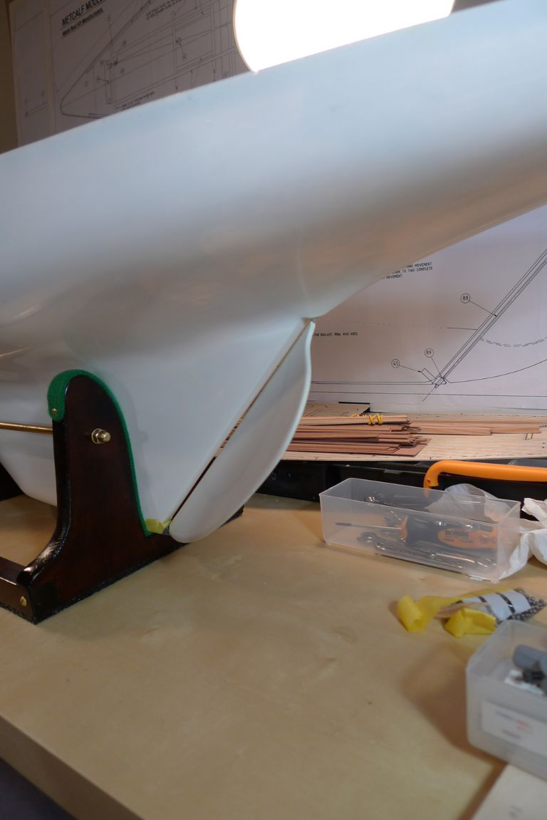
… where it was soldered in place to provide a smoother and stronger bearing than just the lower edge of the rudder itself wou´ld have been. The G-clamp in the above photo did office as heat sink, as the melting point of styrene is quite low. Happily, no plastic was melted by the operation

To be continued …
/Mattias
Edited By Banjoman on 17/05/2016 13:07:56
Edited By Banjoman on 17/05/2016 13:09:47
17 May 2016 at 14:24 #65460Ian Gardner
Participant@iangardner62867It's always worth following your threads Mattias to build up ideas for the future. As I said elsewhere- attention to detail! Not only is the boat being carefully built but your posts are always so carefully presented too.
Ian
19 May 2016 at 09:18 #65504Banjoman
Participant@banjomanThank you very much indeed, Ian, for your much too kind words!
 For my part, I not only enjoy recapping the process, but actually find that it helps me think about what I am doing and why, and to plan ahead for the coming stages of a build.
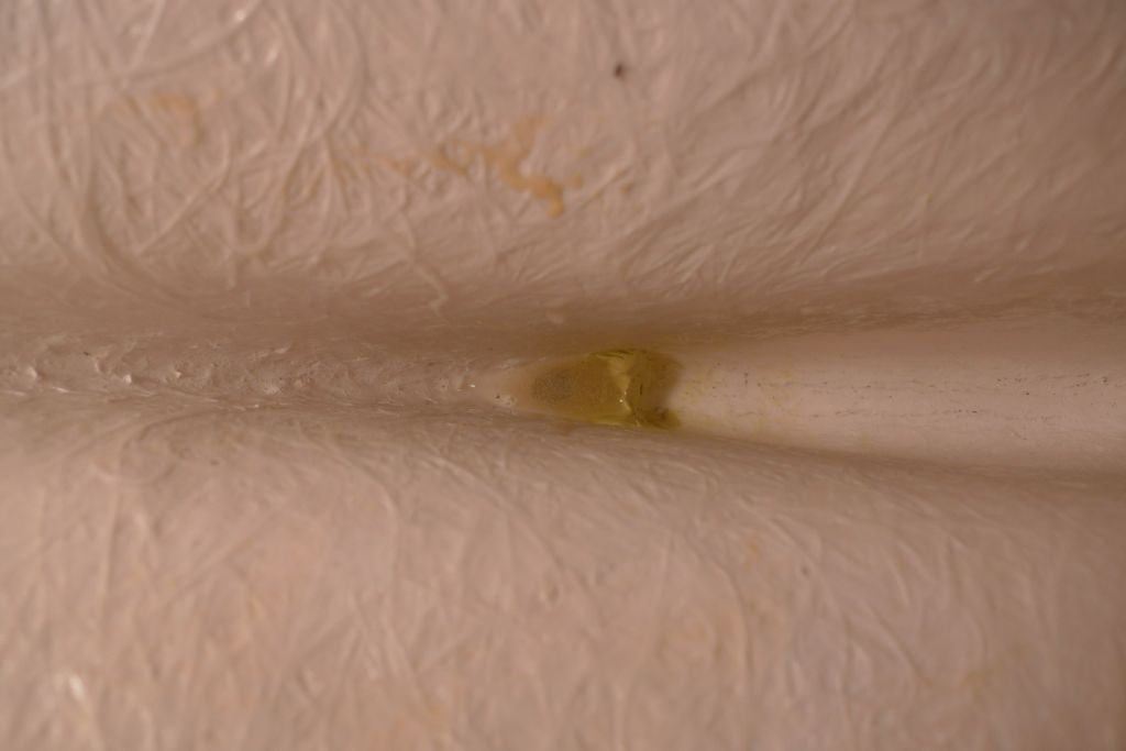
Anyway, the joint between the rudder and the post was given a small filler touch-up with some Milliput …
… to fill out any remaining small gaps and then, once the Milliput had gone off, sanded and polished with finer and finer grades of wet-and-dry paper, ending with some 2500 grit wet paper for a reasonably smooth finish, after which …
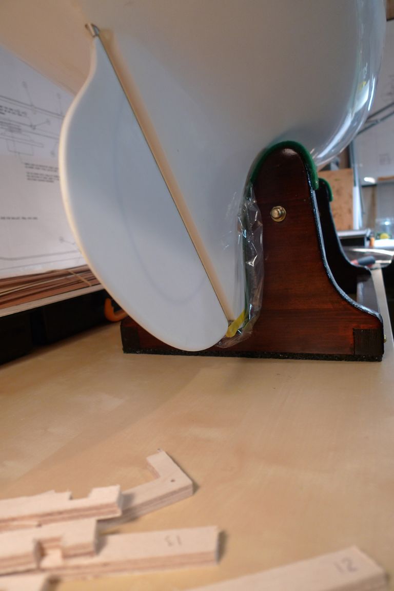
the rudder assembly was dryfitted into place. I am happy to say that it seems to sit just right under it's own weight …
… and that the rudder post turns very smoothly in its bearings. For the upper bearing I have by the way decided to use aluminium rather than brass tube, as that should considerably reduce the risk of a seized-up post, should there be any run-away solder when the servo arm is soldered onto the top of the rudder post at a later stage.
Before I get to that stage, though, there are several jobs that need to be taken in hand, such as making up the servo box for the rudder servo.
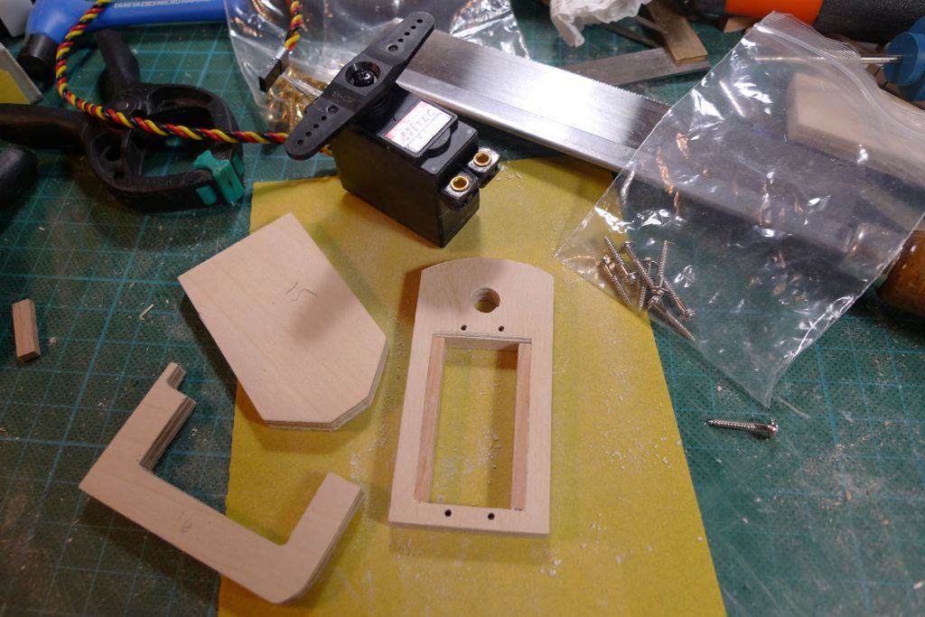
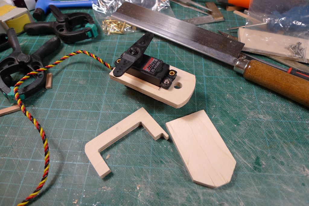
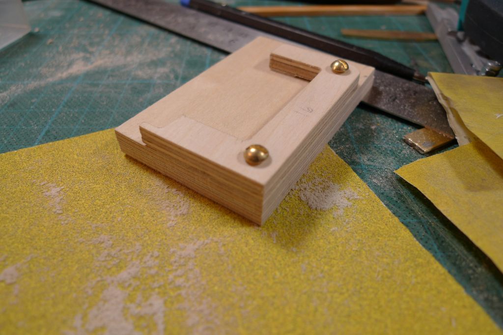
This ox is composed of three CNC pre-routed plywood parts, and I began the assembly by sanding them down and filing out the hole for the servo to sit in until nicely square.
As the hole was also a bit overlarge for the servo, I next added some lining in the shape of left-over strip wood …
…´and then drilled for the servo fastenibg screws …
… which, all in all, should give a strong and stable enough servo mounting.
To be continued …
/Mattias
Edited By Banjoman on 19/05/2016 09:19:14
Edited By Banjoman on 19/05/2016 09:20:10
19 May 2016 at 09:52 #65505Gareth Jones
Participant@garethjones79649Hi Mattias,
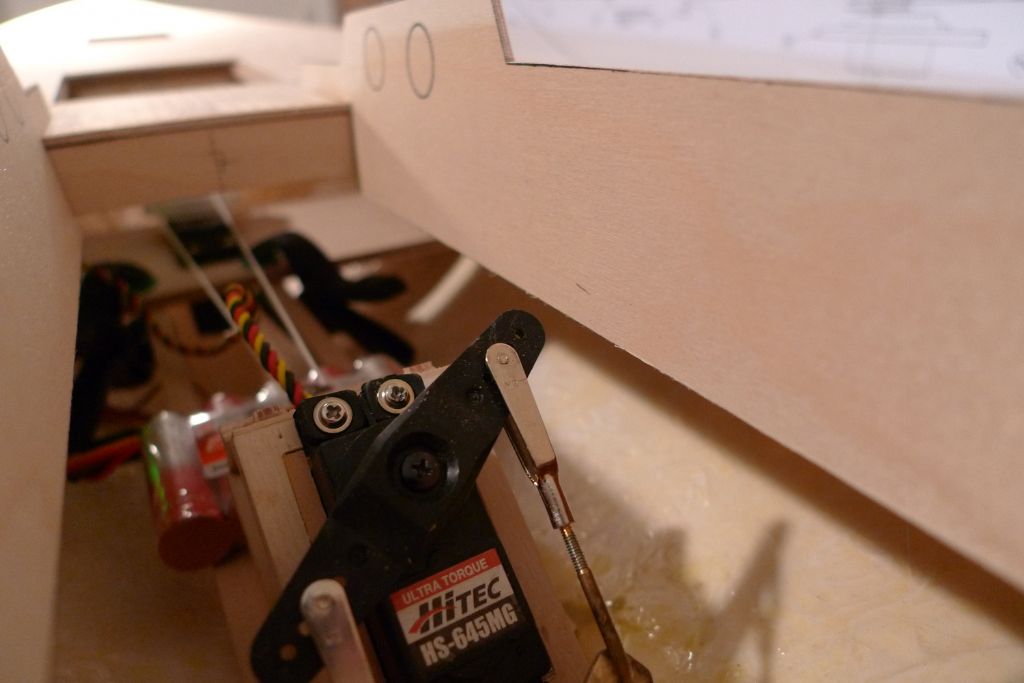
One point to be aware of is that Elizabeth found there was very little clearance between the rudder servo arm and the floor of the cabin structure that fits over the rear access hole. Initially at full rudder, the servo arm was lifting the hatch. It will be difficult to envisage where the cabin floor sits with your model at the stage it is at present. I will take a photo later today to illustrate the issue.
Gareth
19 May 2016 at 10:13 #65506Banjoman
Participant@banjomanHello Gareth,
Many thanks for the heads-up!
As you say, it is rather tricky at the moment to judge just how deep the cockpit well will be, once the deck has been put into place and the aft cabin structure assembled, but I can already think of several things I could do to improve the chances of not having this problem.
For instance, I could make the servo sit a little lower in the hull by cutting a few millimeters of the bottom of the U-shaped joining piece of plywood, and/or replacing the bottom piece of plywood with one that is a millimeter or two thinner.
Likewise, it should be possible to take a millimetre or two off the bottom of the cabin assembly by making the cockpit a tad more shallow.
At this stage, I shall in any case make sure that the servo comes to sit as low in the hull as is comensurate with a good connection with and functioning of the rudder …
Again, many thanks for the warning — and please post a photo! that would be most helpful!
/Mattias
Edited By Banjoman on 19/05/2016 10:13:14
19 May 2016 at 10:16 #65507Banjoman
Participant@banjomanOh, and I forgot to say that the fact that I plan to re-plank the deck with individual planking on top of the pre-printed plywood deck (which thus will be used as a base and rough planking plan only) should also help, as it'll add a millimetre of thickness to the deck, and thus bring the cabin assembly upwards by that much. Not very much, of course, but every bit'll help …
/Mattias
Edited By Banjoman on 19/05/2016 10:17:06
Edited By Banjoman on 19/05/2016 10:17:41
19 May 2016 at 11:01 #65508Gareth Jones
Participant@garethjones79649Mattias,
We solved the rudder servo clearance problem by cropping the 'z bend' ends of the control rods as short as possible. You should be OK if you keep the servo as low as possible to start with. You could, as you suggest raise the cabin floor by a few mm but Elizabeth only realised the problem existed once the whole model was complete and taking the cabin floor off then would have been more difficult. We did not think to operate the rudder servo with the cabin fitted before then. Because the servo is mounted at a steep angle its difficult to envisage where the servo arm will move to when operating the rudder.
Gareth
19 May 2016 at 12:08 #65509Banjoman
Participant@banjomanGareth,
Again, many thanks! This is most helpful, and I will take care to keep the whole servo box/servo profile as low as possible.
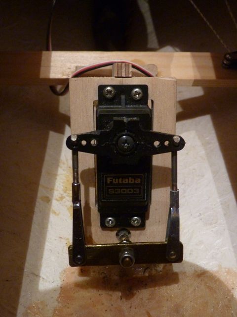
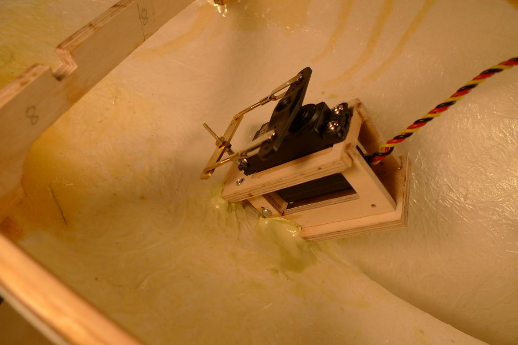
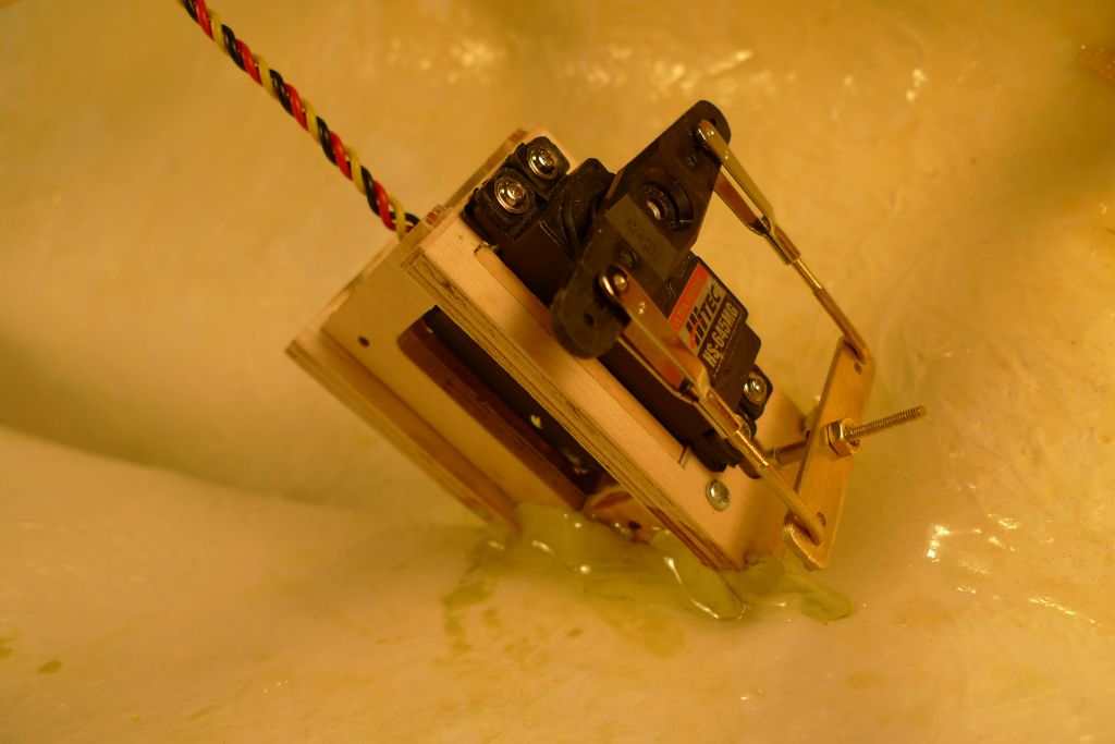
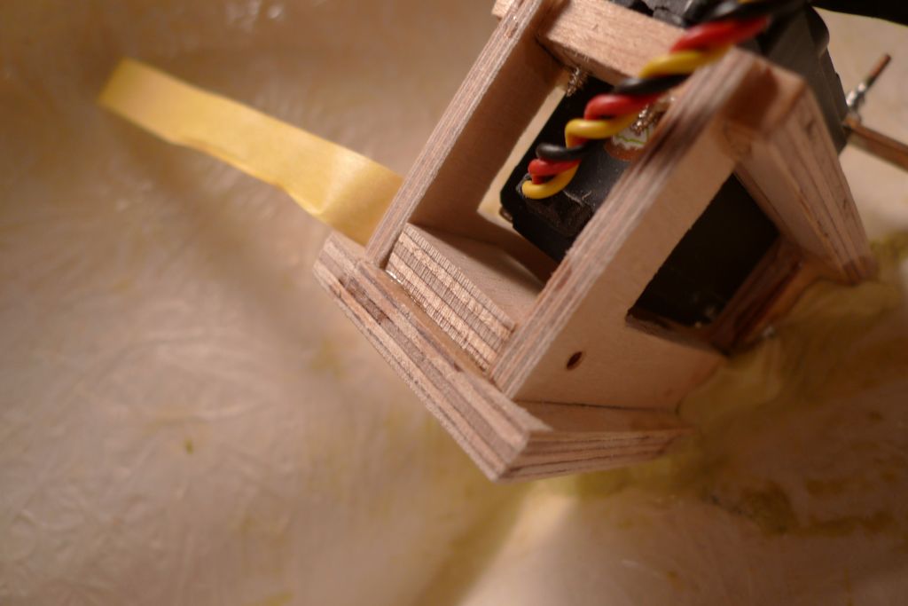
By the way, I note that you dont seem to have had any problems fitting the vertical, U-shape box part around the servo, whereas in my set-up, the servo cable exit is in the way, as the picture below shows:
It is not that big a deal, though; I am thinking of making up a double of this part, and have two them in parallell, something that incidentally should also make for a stronger construction.
/Mattias
20 May 2016 at 22:06 #65559Banjoman
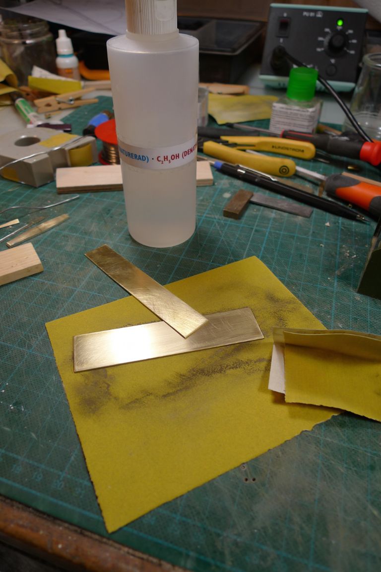
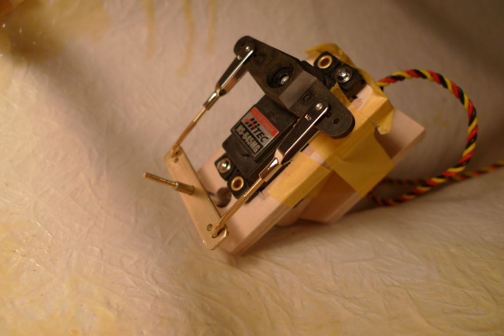
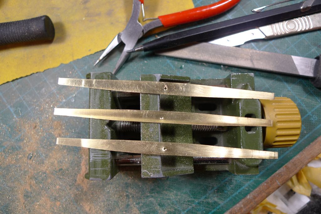
Participant@banjomanTonight, I made up the rudder yoke, and although a small piece of brass sheet came with the kit for that purpose, I decided to make it slightly sturdier by doubling the thickness, and therefore instead cut off a few strips of 0.8 mm brass from a sheet that I had lying around. These strips were then thoroughly scoured with abrasive paper and degreased with methylated spirits …
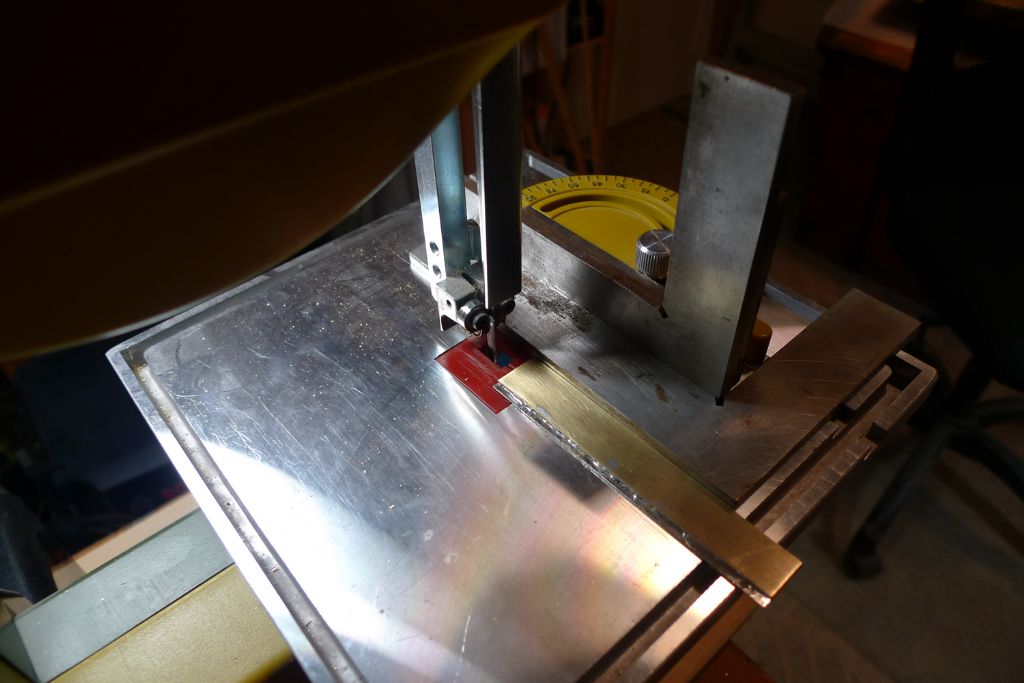
… before being soldered together and cut out on the bandsaw …
.. to form a 1.6 mm thick by 8.5 mm wide strip of brass.
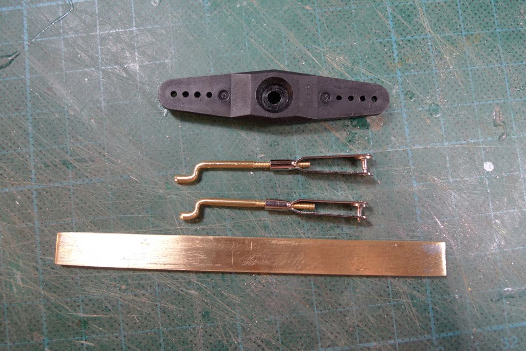
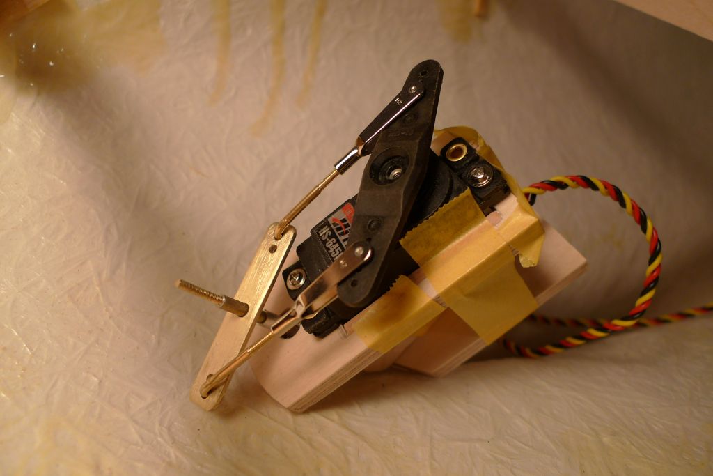
I also made up two short pushrods from 2 mm brass rod, cutting M2 threads at one end of them. I know full well that brass rod would normally be considered ond the soft and weak side for pushrod work, but given how short they are, I don't think it will be a problem, and as it is so much easier to cut threads in brass than in piano wire, I decided to go for that material.
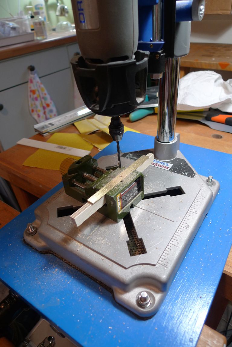
Next, a 3 mm hole was drilled in the centre of the brass strip …
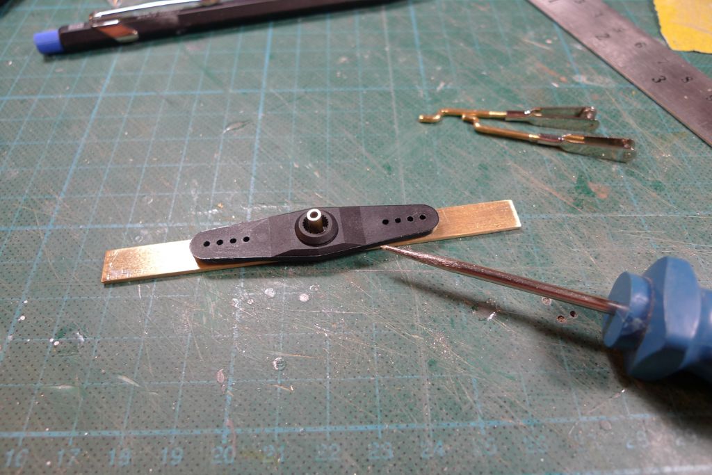
… and the points corresponding to the two innermost pushrod holes in the servo yoke marked out …
… and drilled for 2.1 mm holes to take the z-ends of the pushrods, after which the yoke was cut down to 48 mm wide and the ends rounded off slightly.
Everything is of course only dryfitted so far (as one would if nothing else assume from the fact that the servo box is held together with masking tape), but just to make sure, I connected the r/x and a battery to the servo, and verified that there is room between the rudder yoke and the hull for a full servo arm movement.
To be continued …
/Mattias
Edited By Banjoman on 20/05/2016 22:07:37
Edited By Banjoman on 20/05/2016 22:08:49
23 May 2016 at 07:27 #65594Banjoman
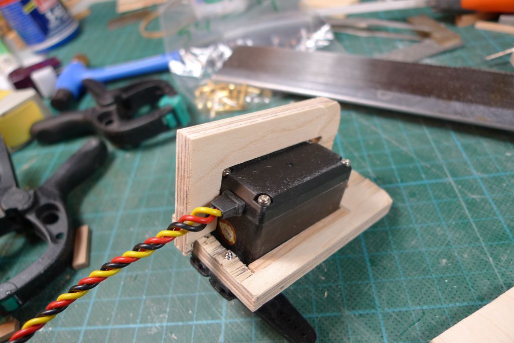
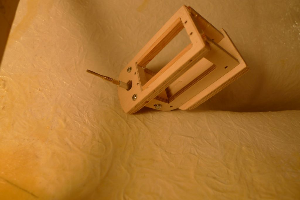
Participant@banjomanSeeing that the upright part of the servo box did not fit very well around the servox cable exit, I ecided to replace it with two similar parts, either side of the servo.
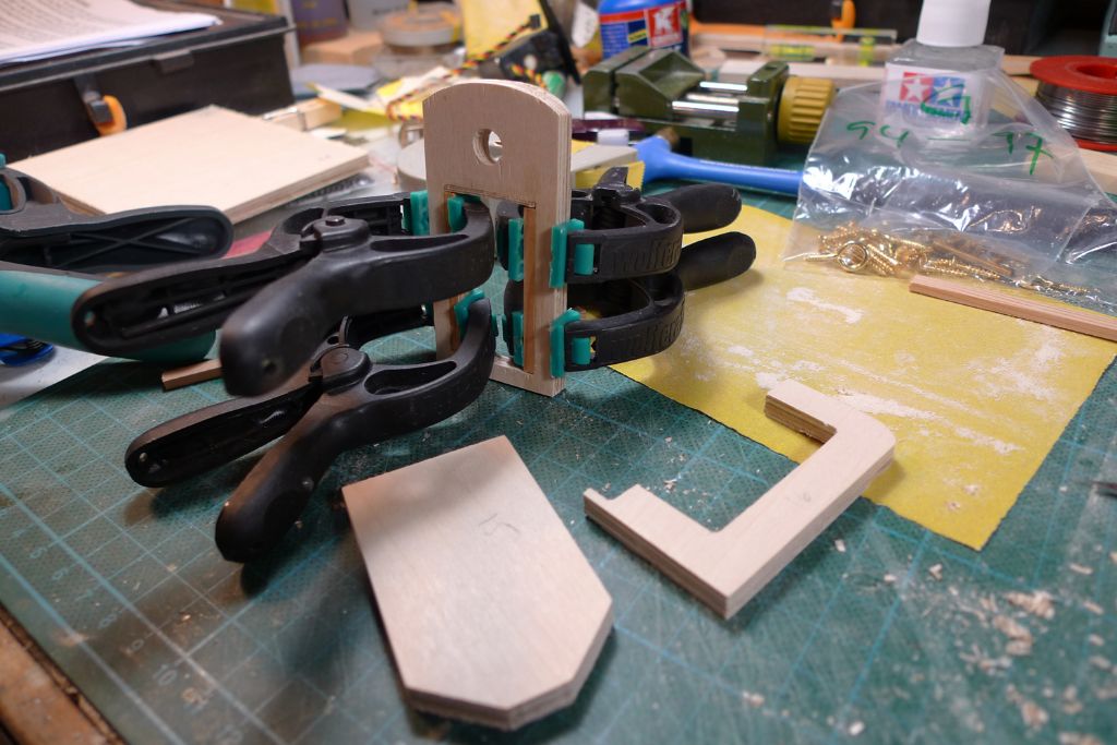
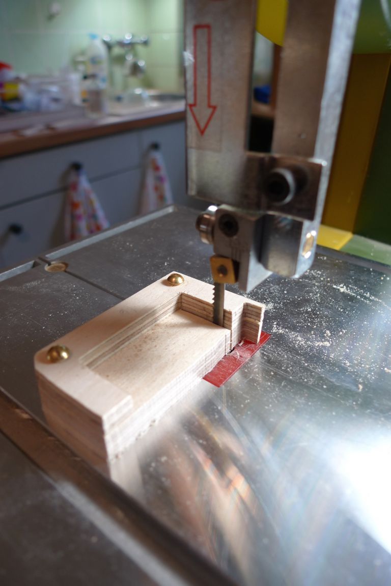
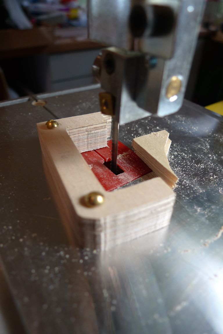
In order to make up two identical copies in one go, I got two rectangular pieces of 4 mm ply, lined up two of their outer edges with the two straight outer edges of the original part, drilled through and screwed all three together to form a block.
It was then easy enough to cut out the two new parts on the bandsaw …
… using the shape of the original as guide.
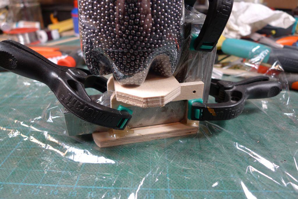
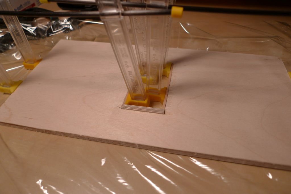
After some further sanding to final shape, the two new uprights were epoxy glued to the underside upper part, with some trysquares (wrapped in clingfilm to keep the glue from sticking to them as well) inbetween to ensure they stayed perfectly perpendicular and parallell to each other while the glue set.
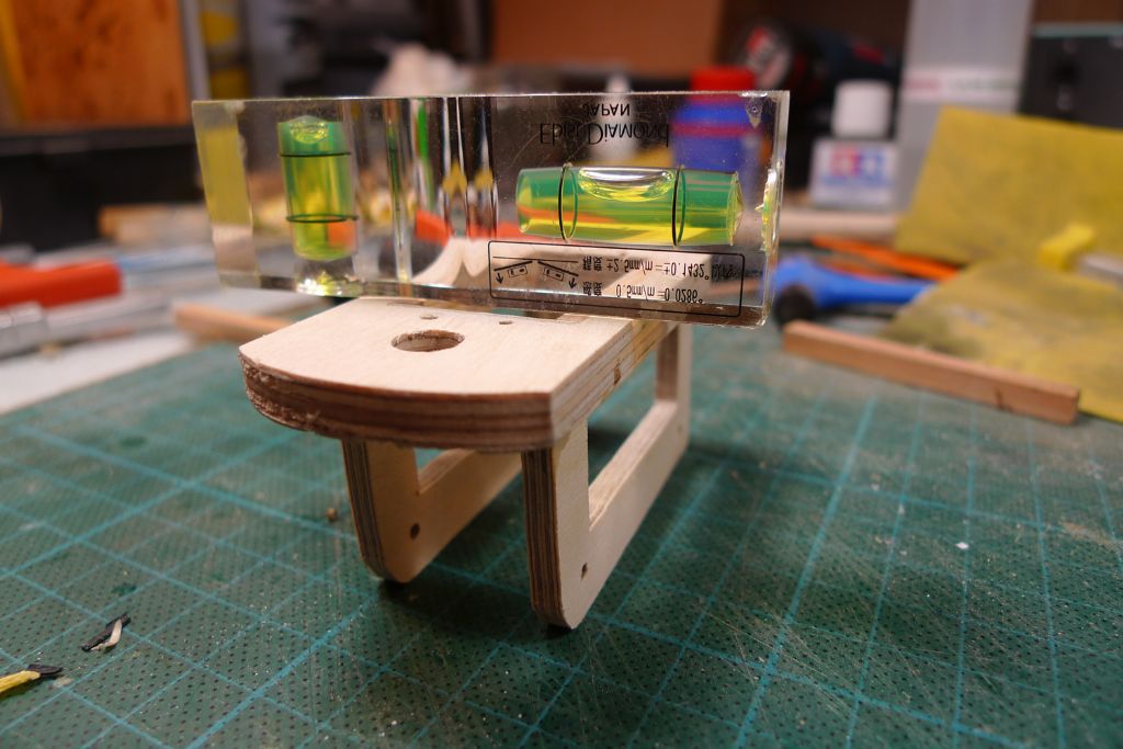
Once the epoxy had gone off, I checked the assembly and found that the resulting servo platform was indeed suffiiently level. There remains the lower part of the box to add, and also a block, shaped to go tight up against the rudder post shaft, but I won't add these until the rudder assembly has been fixed in place permanently, to be sure that final shaping of the servo box where it shall sit against the hull can be made with orrect reference to the rudder post shaft.
To be continued …
/Mattias
25 May 2016 at 07:00 #65622Banjoman
Participant@banjomanI have been very much in two minds tha last week about whether or not to further reinforce the joint between rudder post and rudder blade by adding brass strips around the post and across the blade; I'd even gone so far as to preparing sme brass strip blanks for the purpose …
In the end, though, I decided against this: for any real additional strength to be achieved, the strip would have had to be bolted through the blade in at least one spot, and even with a M1 micro nut-and-bolt assembly, I felt the rudder would have taken on a Frankenstein's monsterish sort of appearance, which would have quite broken up the smooth beauty of the lower hull lines.
Having tried it in the hand, I would in any case say that the present joint — made entirely according to the instructions — is fit or purpose, and although a sailboat rudder does indeed have to contend with a fair amount of force, I think it will be up to the job as it is.
I thus contented myself with a weaker, but also much less obtrusive, pinning-through of the post into the blade in several places …
… and then glued the skeg-and-rudder assembly into place, with a small amount of 24 hour epoxy on the outside surfaces …
… and a pool of the same epoxy all around the skeg tang on the inside of the hull, behind a small dam made up of Milliput.
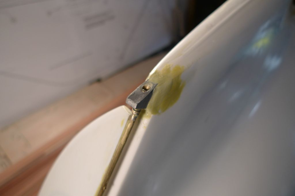
Once the epoxy hade gone off fully, i.e. the next day, the joint between the skeg and the keel was filled in and rounded off with some more Milliput …
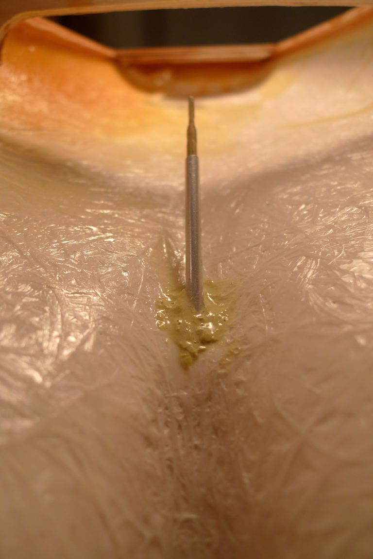
… with the help of which I then also fixed the rúdder post tube in place. Once the servo box is in place, I shall further fill out and reinforce this joint, but for the time being this should be enough to keep everything sufficiently strong and steady for continuing the build.
To be continued …
/Mattias
26 May 2016 at 07:11 #65638Banjoman
Participant@banjomanNext, a reinforcing block of wood with a half-channel filed into it to fit around the forrard half of the rudder tube was glued into place, with a short length of identical tubing temporarily held in place while the glue went off to ensure correct placement.
The bottom piece of the servo box was also glued into place …
… and the glue joints between the main pieces of the box further secured with some strategically placed wood screws.
With this, the servo box was finished, and could be fixed in its place with a combination of Milliput and 24 hour epoxy. Once this has gone off, the remaining space between the box and the hull shall be completely filled with more of the same. This could of course fairly easily have been done concurrently with the rest, but as the structure had just been adjusted for the servo arm to sit at 90 degrees and the servo axle parallell to the rudder post, I preferred not to have to realign the whole thing anew, and it will be even esier to do the job with everything solidly fixed in place.
For the sake of clarity I should perhaps add that when I say "a combination of Milliput and 24 hour epoxy", I don't mean that I actually mix the two together, but rather that I use both next to each other and at the same time. The Milliput allows one to create barriers behind which the epoxy can be applied without running out, and as neither stops the other from going off or (as far as I have been able to tell) has any affect whatsoever on the other, they can both be applied "wet" at the same time.
In this particular instance for example, I added some Milliput underneath and around the lower, inner edge of the whole box, thereby createing an enclosed pocket around the lower part of the rudder tube. This pocket was then filled with a good dollop of epoxy by simply pouring it in and letting it run down the upper side of the lower peice, just beneath where the servo wires come out.
To be continued …
/Mattias
Edited By Banjoman on 26/05/2016 07:11:39
Edited By Banjoman on 26/05/2016 07:12:19
26 May 2016 at 08:45 #65640Ian Gardner
Participant@iangardner62867Very neat and inspiring work Mattias. Great idea about the use of Milliput and epoxy- will store that away for future use.
Ian
30 May 2016 at 08:15 #65724Banjoman
Participant@banjomanWith the servobox firmly fixed in place, it was time to solder the rudder yoke to the rudder post.
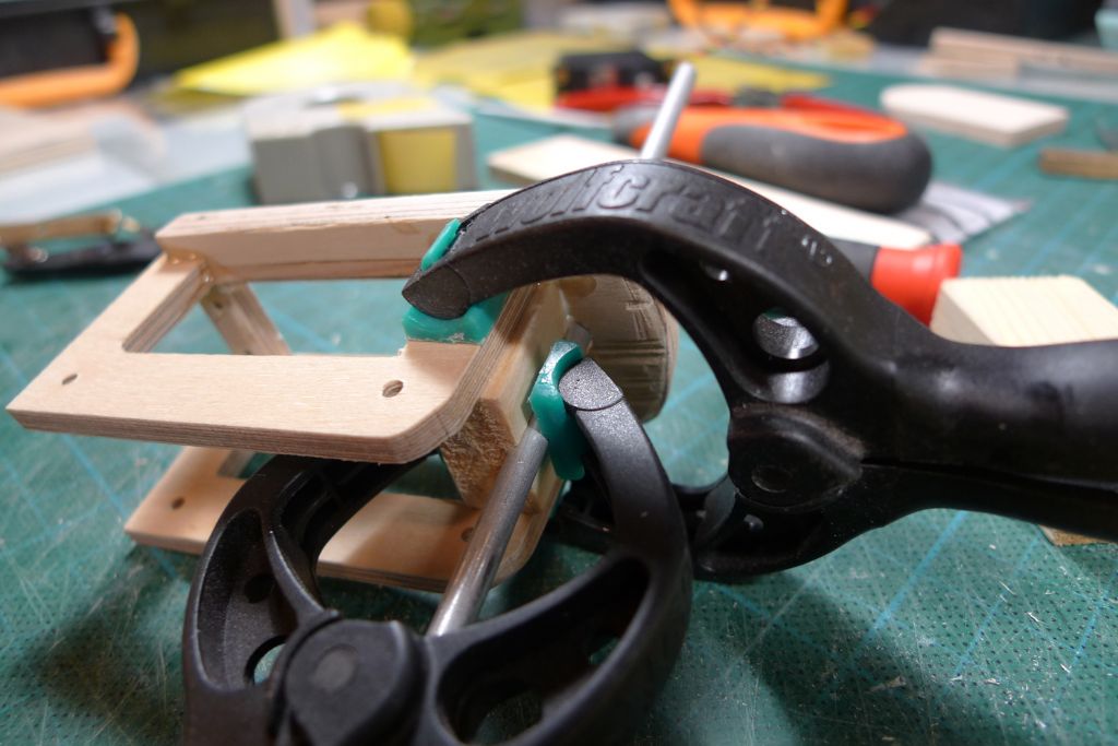
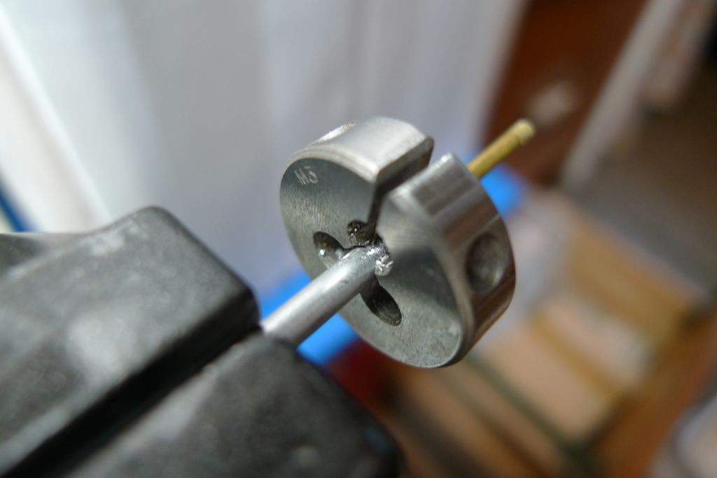
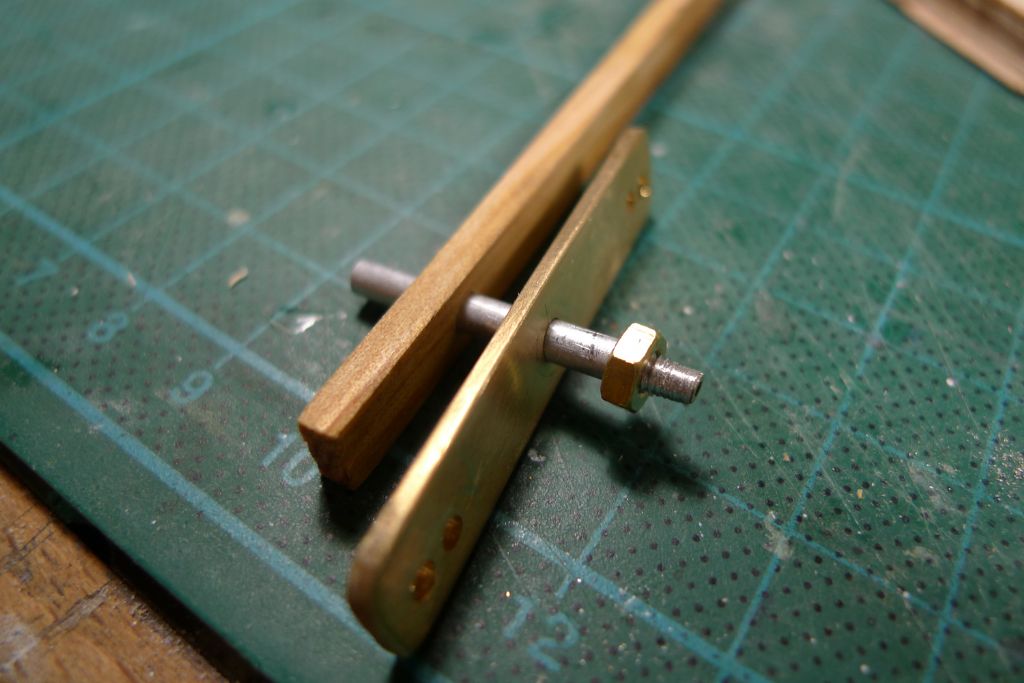
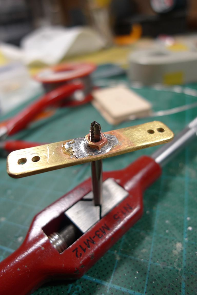
As previously mentioned, the top end of the rudder post has had respectively M3 and M2 threads cut into it, and so I decided to start by soldering a M3 nut to the underside of the yoke. In order to be able to do this off the model with both parts correctly aligned, I first created a small jig in form of a short length of 3 mm aluminium tubing wih a M3 thread cut into one end. To keep the tube from twisting and/or collapsing under the die, I slid some 2 mm brass rod through the tube.
The nut was then screwed on to the tube, and the assembly slid through first the yoke and then a short length of wood; this was then set up in a small machine vice, with some more wood in the jaws to prevent the vice from becoming a heat sink …
… and the yoke-and-nut fluxed and soldered together. As the solder did not grab on the aluminium, it was then easy to unscrew the tubing, after which excess solder could be cleaned out of the internal thread with an M3 tap.
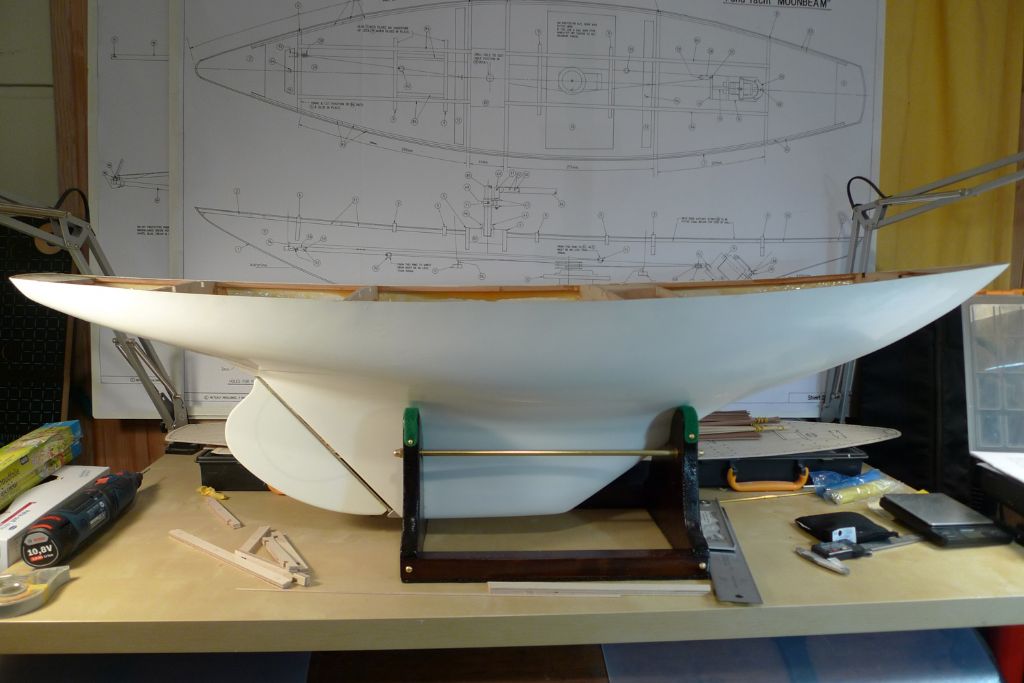
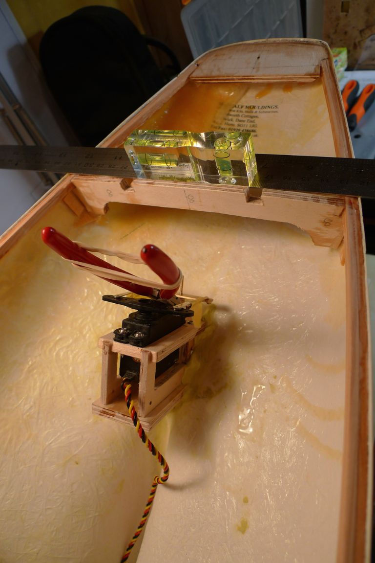
Next, a second nut was screwed onto the rudder post, with the the yoke screwed down over it. I then checked that the hull as it sat in the stand was level athwartships, to acheive which the starboard side had to be raised by a couple of millimetres.
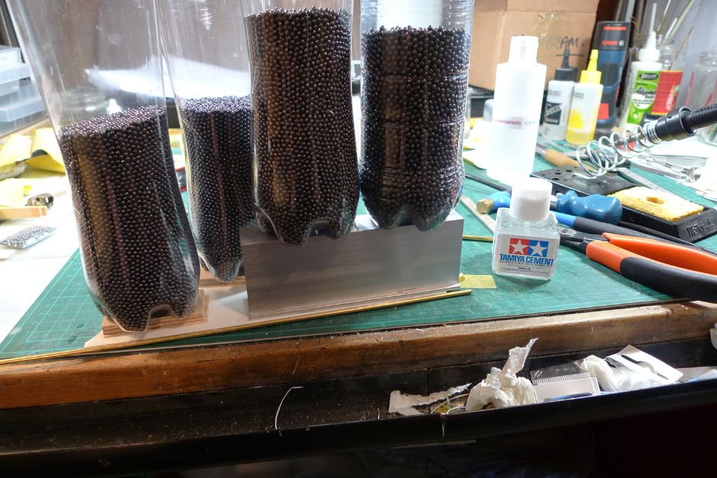
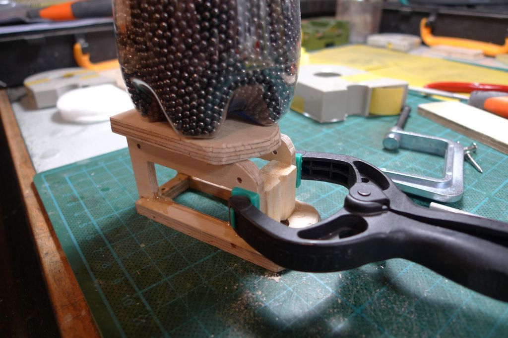
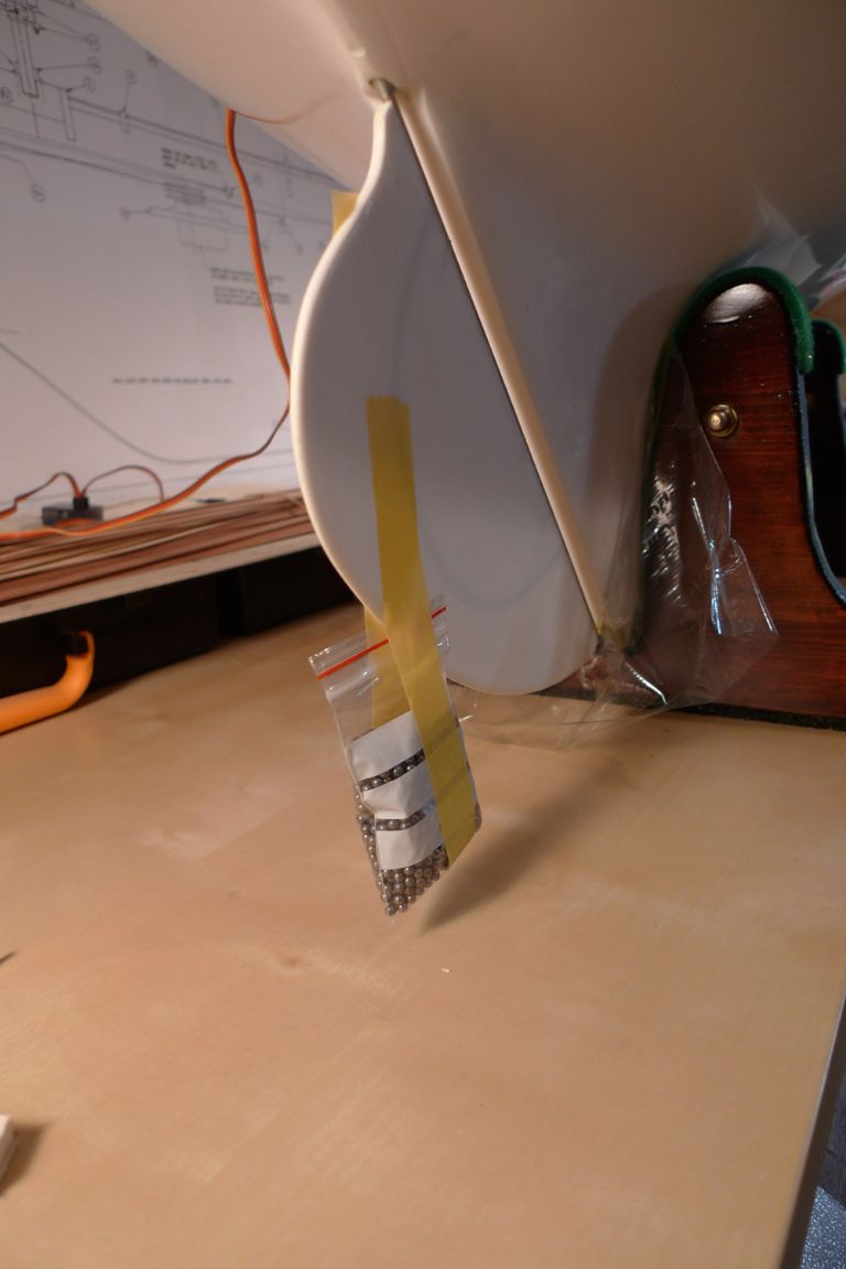
I then taped a bag with 150 grams of lead shot to the rudder, to ensure against it moving out of true while soldering.
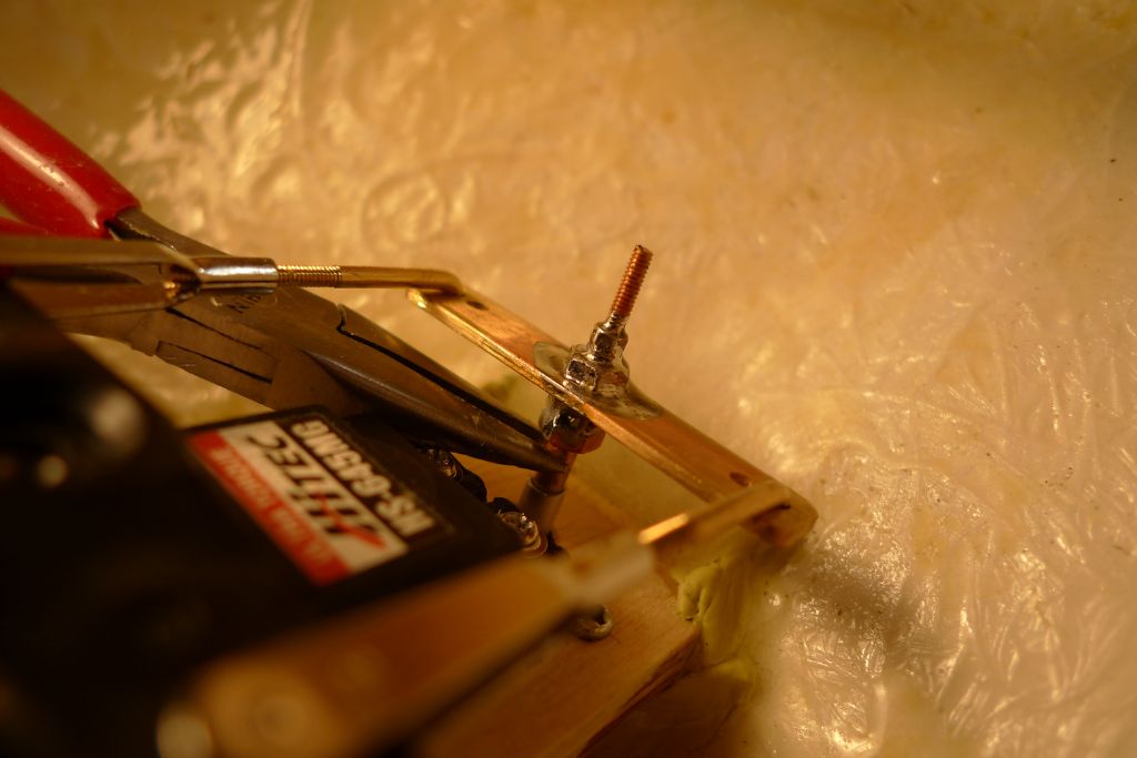
With the yoke properly adjusted for height in relation to the servo arm, the lower nut was tightened onto the underside of the yoke nut, and the yoke and two nust soldered to each other and to the post. Next, a further M3 nut and two, smaller M2 nuts were screwed down on top of the yoke, and also soldered to the yoke, the post and of course each other.
For a heatsink, I used a pair of pliers to keep the heat from damaging either the hull or (more likely) the styrene rudder. This worked well enough and allowed me to crank the soldering station up its maximum temperature of 450º C, for a good capillary solder flow.
The finished joint seems strong enough, and at standard servo travel, the rudder moves some 45 degrees or so to either side. As I suspect that that much rudder movement will not be necessary, and might even lead to too sharp turning, I suspect that I shall reduce the servo movement to somewhere in the region of 80%, but that will of course need to be tested and finetuned on the water …
To be continued …
/Mattias
Edited By Banjoman on 30/05/2016 08:19:08
2 June 2016 at 12:15 #65814Banjoman
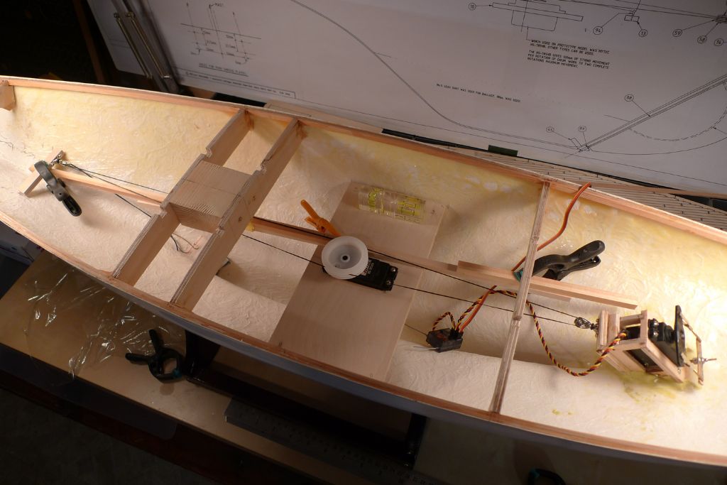
Participant@banjomanWith the rudder and steering sorted, it was time to turn to the ail winch installation. As with the rudder servo box, the opening in the sail winch holder was clad with offcuts for a nice and tight fit.
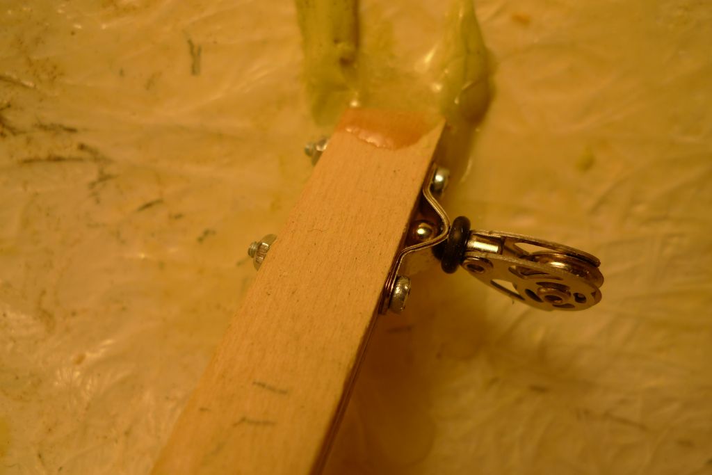
The continous loop requires a pulley at either end, the aftermost of which is supposed to be attached to the rudder servo box. However, I had early on decided to replace the simple white metal pulleys that came with the kit …
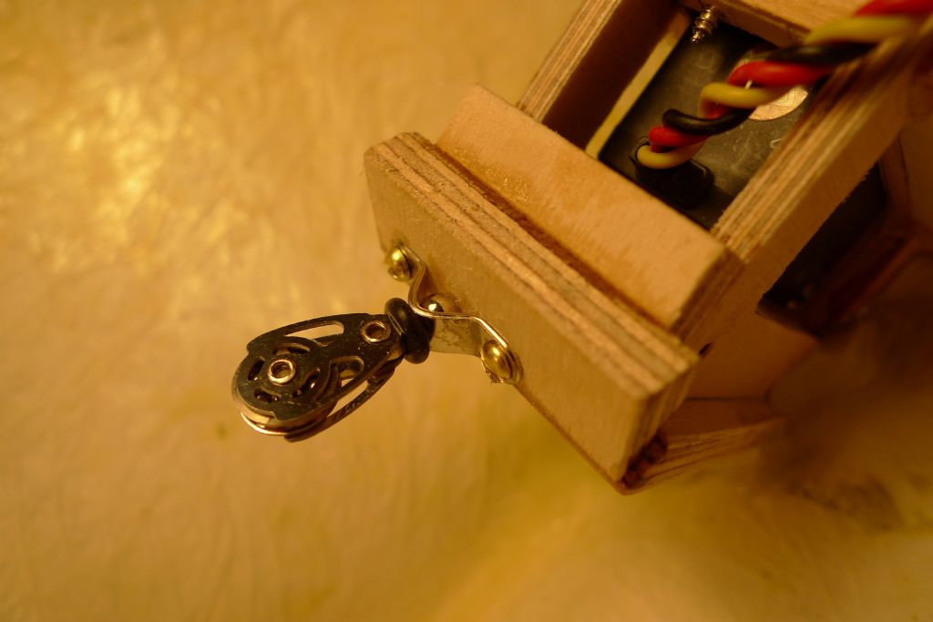
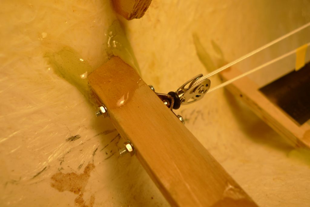
… with more smooth-running and (I think and hope) reliable ones. In the end I opted for ballraced metal pulleys from CAP Maquettes, which combine high-end function with good (at least to me) looks (the latter is of course of littel consequence here, below decks, but it will make a difference in the rigging). For the winch loop pulleys I further decided on swivel rather than shackle mounted ones, and therefore the forrard end of the servo box needed a perpendicular surface.
This was created by first adding a filler piece below the servo (see photo above) and then glueing two pieces of plywood with one edge on each bevelled to a 45° angle on top of that.
The pulley could then be fastened wth a couple of wood screws into this assembly.
When mounting the forrard pulley next, however, my lack of previous experience with this sort of installation played me parts, and I managed to misunderstand the instructions as given by the plans.
What happened was that I assumed that the loop cord should lie as flat as possible between its three points of reference, i.e. the winch and two pulleys, and I therefore decided to deviate from the plan, and to set the forrard pulley holder lower down in the hull than what is marked on the plans.
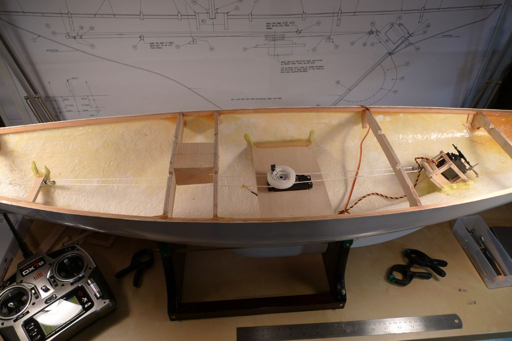
With the help of some cord and some strip wood, I carefuly aligned pulleys and winch to sit on a straight line …
… and then fixed the winch and forrard pulley holder in place.
When the Milliput and epoxy had gone off, and I rigged the continous loop, however, I realised that I'd made a mistake …
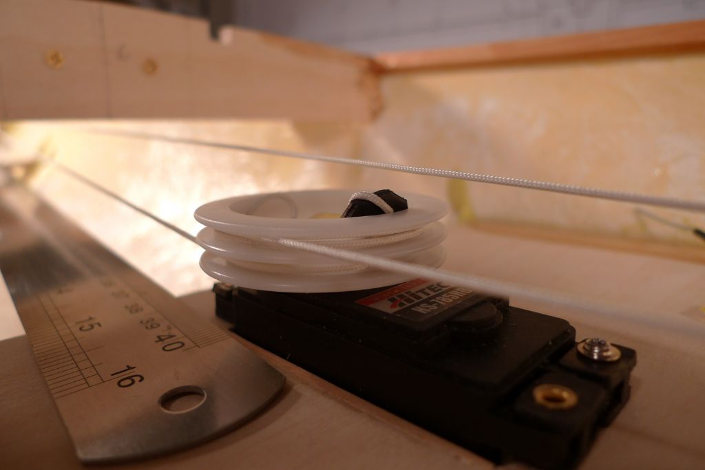
… as this set-up meant that the starboard part of the loop, which does not lie on the winch drum, came to rest naturally just under the drum.
For the loop itself, this would not be too problematic — I tested it for a goodish while, and it worked fine as it was. However, given that the two foresail sheets needs to be made fast aft of the winch drum and then pass up through the deck forrard of it, any slack in either sheet would be liable to get caught up on the drum.
Further study of the plns made it quite clear that in order to avoid this, the starboard part of the loop is specifically intended to run above the winch, well clear of the drum, and that to achieve this, the forrard pulley and its holder needs to sit where the plans say they should!
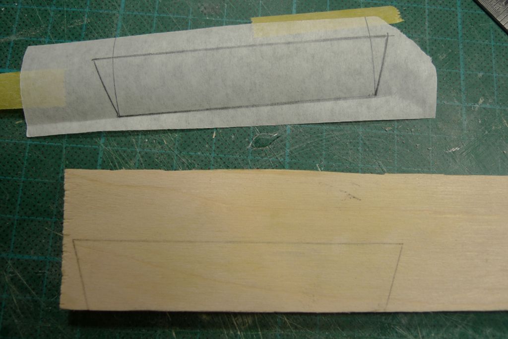
So: the shape of the part in question was calced from the plans, and transferred to a plywood cutoff …
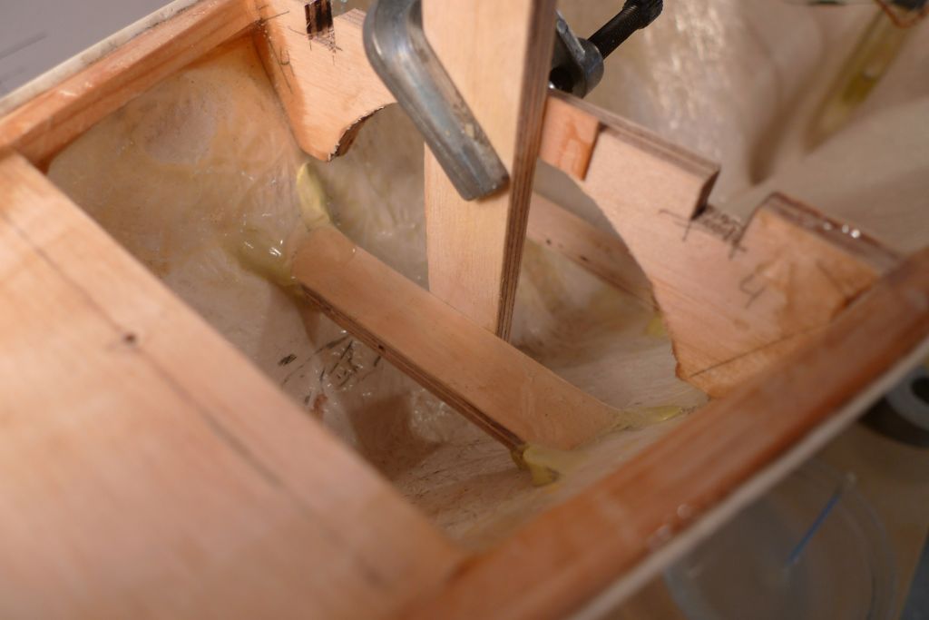
… and a new pulley holder produced, and fixed in place. The vertical piece running down from the deck beam is only there as temporary support, though, to keep the pulley holder from sliding forward while transversally adjusted.
The first holder was left in place; it can be seen just below the deck beam. I don't think it will be in the was of anything where it is, so there is no particular reason to remove it, but if it proves a bother for some reason it can of curse be taken out later.
Oh well, we live and learn!
To be continued …
/Mattias
Edited By Banjoman on 02/06/2016 12:17:33
Edited By Banjoman on 02/06/2016 12:20:44
2 June 2016 at 21:44 #65819Banjoman
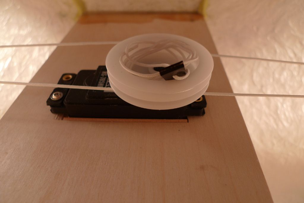
Participant@banjomanWhen everything had gone off, the pulley could be reattached, and the loop re-rigged …
… this time with a ratter better run along the starboard side, well above the drum. To add braces to my belt here, though, I think I might also try adding a protective hood to cover the drum and that much more securely keep the sheets out of potential harm's way.
In any case, I also did some rough measuring of the length of the loop run, and found that at 100% servo throw, it would move some 350 mm or so. By reducing the throw to 65% in both directions, full movement of the stick gives a loop run of +/- 275 mm. The instructions seem to recommend a 240 mm run, but I'll verify all that once the mast, booms and sheets are in place, and the settings can be tested in practice.
To be continued …
/Mattias
Edited By Banjoman on 02/06/2016 21:45:30
5 June 2016 at 09:44 #65850Banjoman
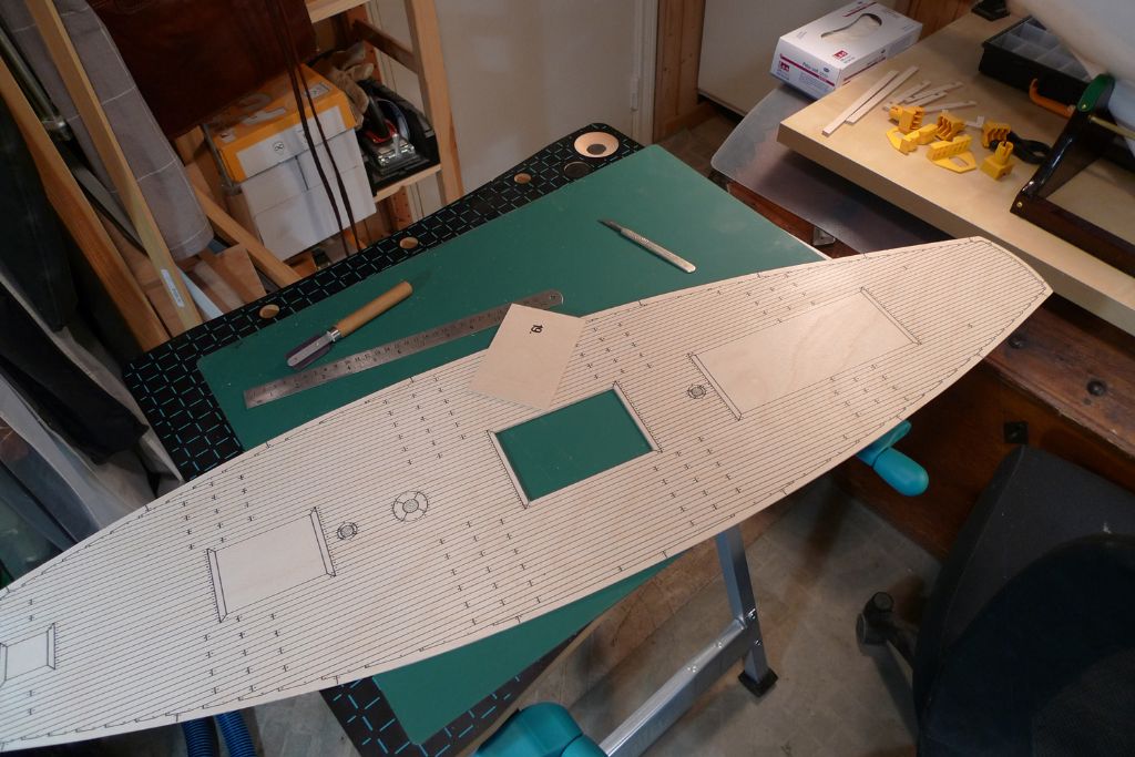
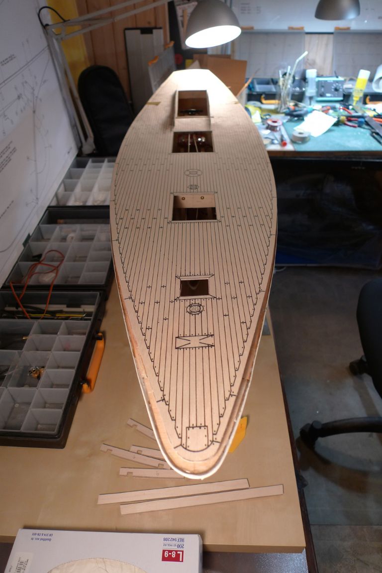
Participant@banjomanThe other day, I began cutting out the openings in the deck …
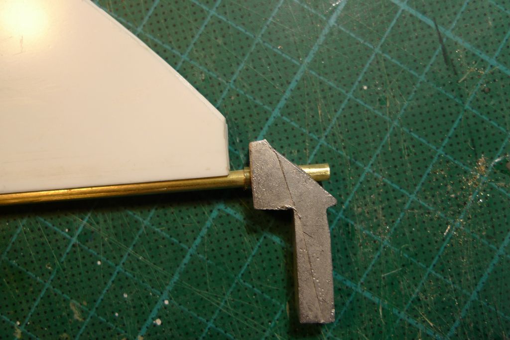
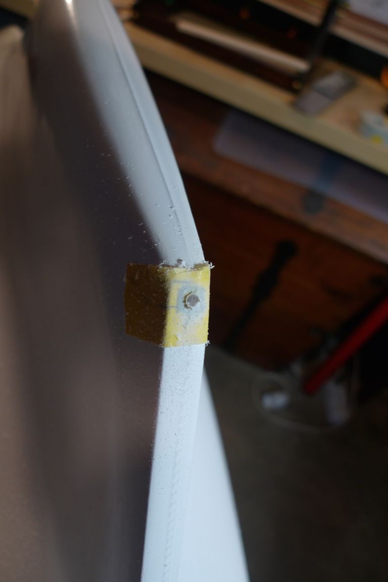
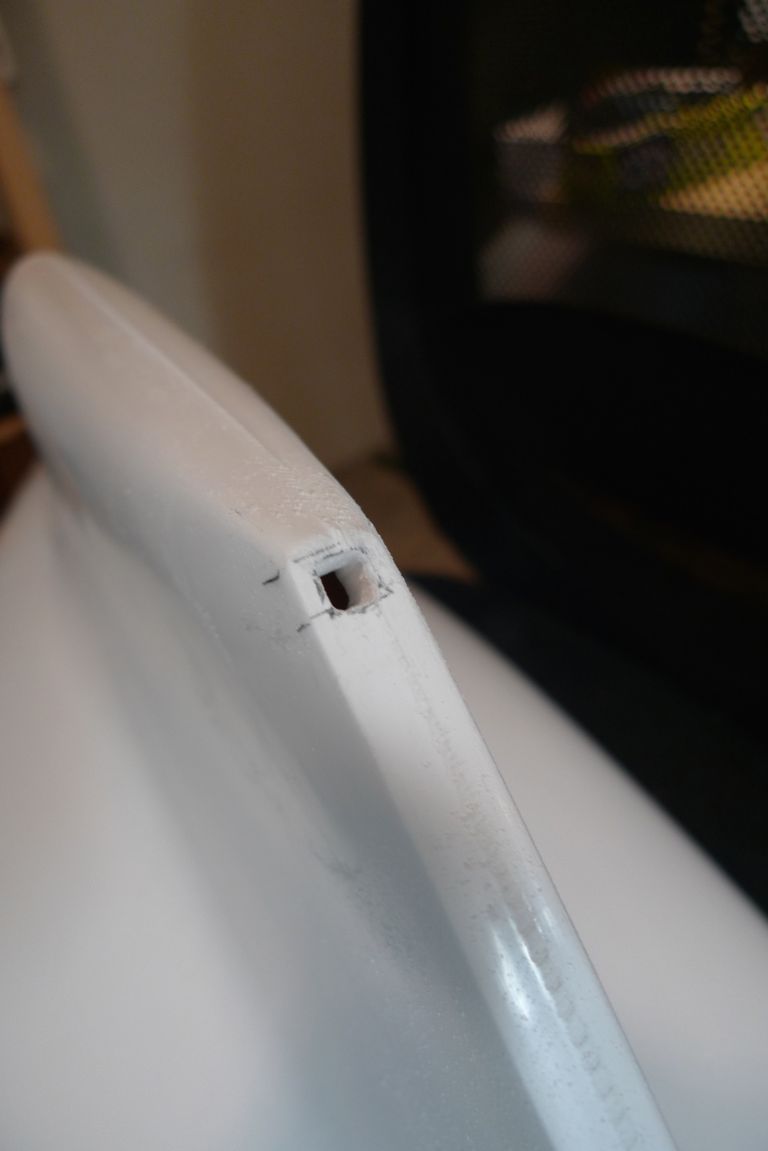
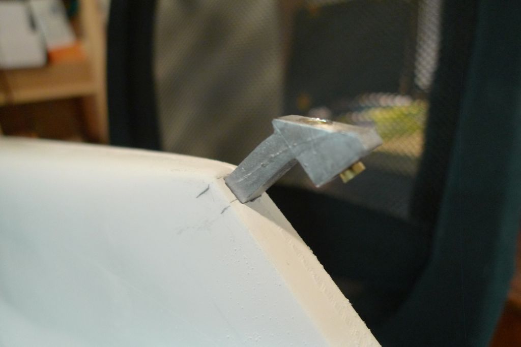
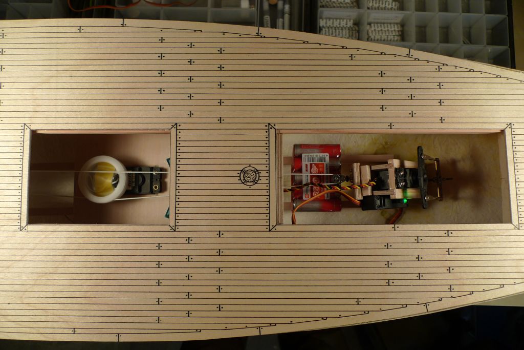
,,, and quickly realised that this is a job I ought to have done much earlier, as it turned out that I had missed the instructions implicit from the plans, namely that the aftermost opening, where the cockpit structure will sit, uses the two aftermost deckbeams as transversal coamings!
This means that they should have been placed in the hull so that they would sit flush with the fore and aft edges of the opening. The good news is that they did indeed fit the opening very neatly where I had glued them in place …
… the bad news is that they were both too far aft by about 6 mm, which meant that the deck overlay would have to be trimmed back considerably to fit, and thus run short in the bows!
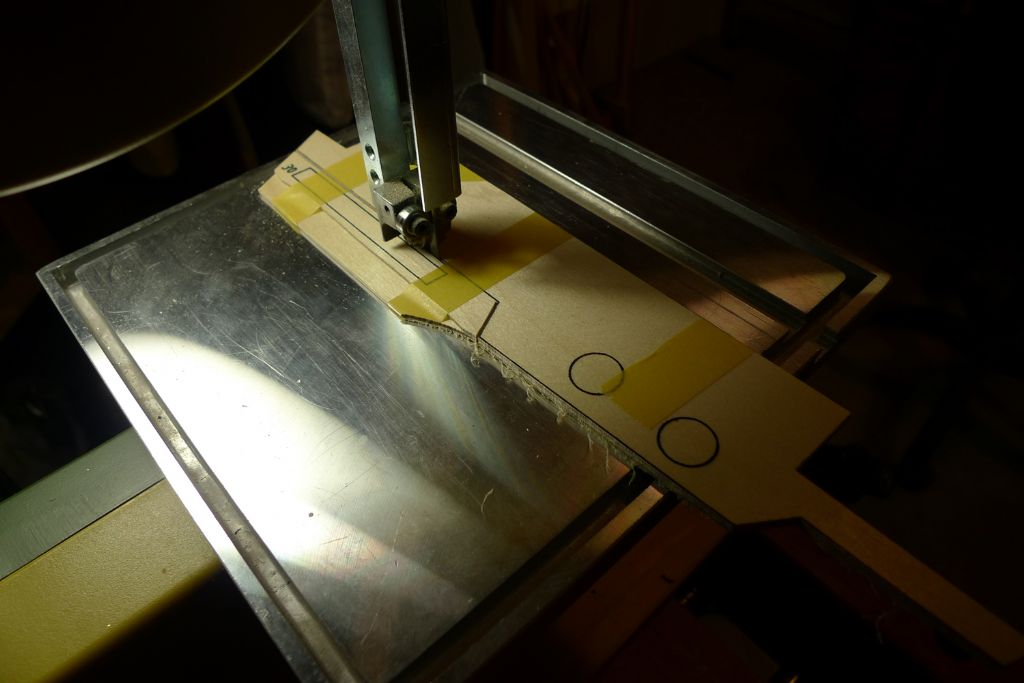
Before going any further, I decided to also check the fore-and-aft fit of the cockpit structure. I therefore cut apart the two side panels along the line joi9ning them on the printed plywood, and then taped them together using this line as reference point. This way, they could both be cut out together on the bandsaw, resulting in two identical pieces. This also had the further advantage that it allowed me to turn the bundle over as required, to cut along a corresponding line on the side of the bundle that allowed me to turn the longest part of it away from the bandsaw throat.
A quick dryfit confirmed that the cockpit sides are a perfect fit for both the opening and the current ditance between the two troublesome deck beams, which was of course in a way quite good news, as it meant that at least the relative distance between the beams was correct.
I also made an initial check of to what extent the play of the rudder servo arm might risk being hindered by the under part of the cockpit structure, and noted that I shall indeed have to be quite careful when I get to the stage of constructing it, or I might encounter the same prioblems mentioned by Gareth in an earlier post.
Anyway, I now had to consider my options, and ddismissed out of hand the idea of trying to take out and reinstall the beams, as this would most likely damage the hull, and it would not be an easy operation anyway.
I also quickly discarded plan (a), i.e. to leave the beams as they were, and shift the whole deck aft. OK, I am planning to replank the whole deck, so from that point of view it would't matter, as any filler (and there will be some needed anyway) would be hidden under the planking. However, it woould also mean that the mast would be shifted 6 mm aft. I have no idea to what extent this would (or would not) affect sailing and the general balance of things, but I would rather not find out the hard way that it was a bad idea.
Yes, a plan (b) it would of course be feasible, by which I would just move the location of the mast fiorward again by 6 mm, irrespective of where its preprinted location is on the plywood sheet, but gis would have the knock-on effect of making the location for the foresail sheet deck throughput sit uncomfortably close to the next hatch opening in the deck.
Nor were I particularly keen on plan (c), which would have meant utting the whole deck in two somewhere amidships, trimming off the aft end, putting down the forrard part as intended and then filling in the missing 6 mm with some scrap plywood.
To be continued …
/Mattias
5 June 2016 at 09:44 #65851Banjoman
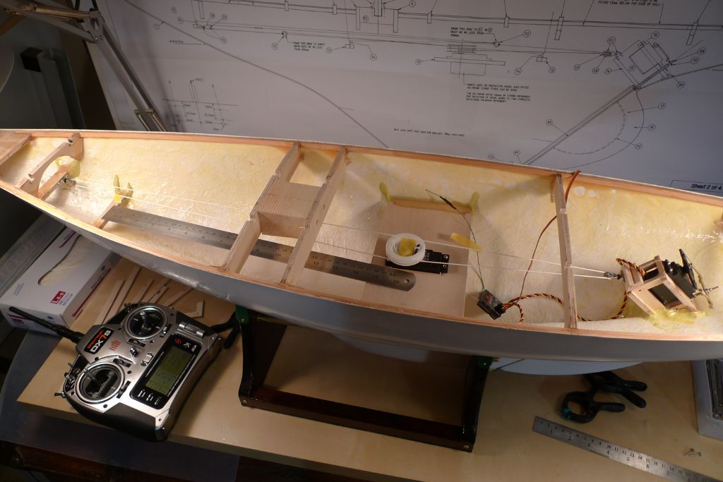
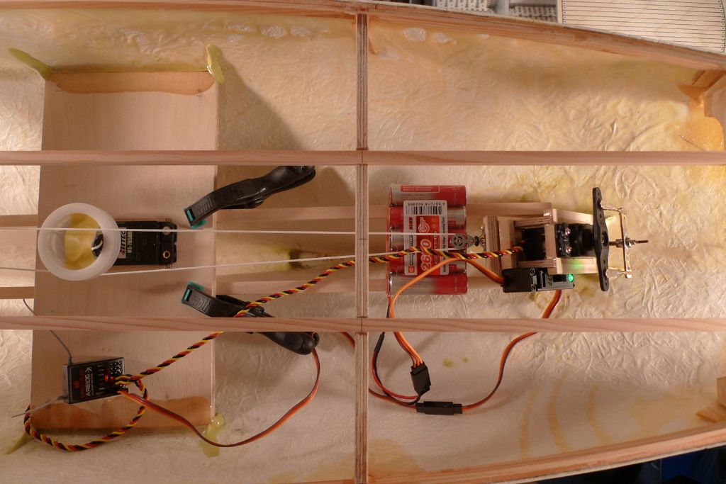
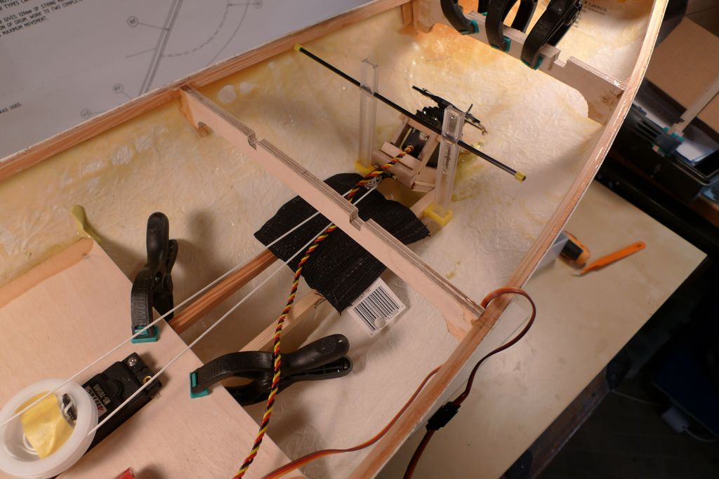
Participant@banjomanWhile still pondering what to do, I also begun a think about where to install the r/c components. The reciever will fit quite nicely to one side of the sail winch platform, but I was less keen on putting the battery there, as, although not very heavy, it would still be a little bit of a weight off to one side of the hull.
I therefore decided to add a couple of stringers between the underside of the sail winch platform and the rudder servo box on which the batteries can rest, and also checked that it would be possible to reach them there through the available deck openings.
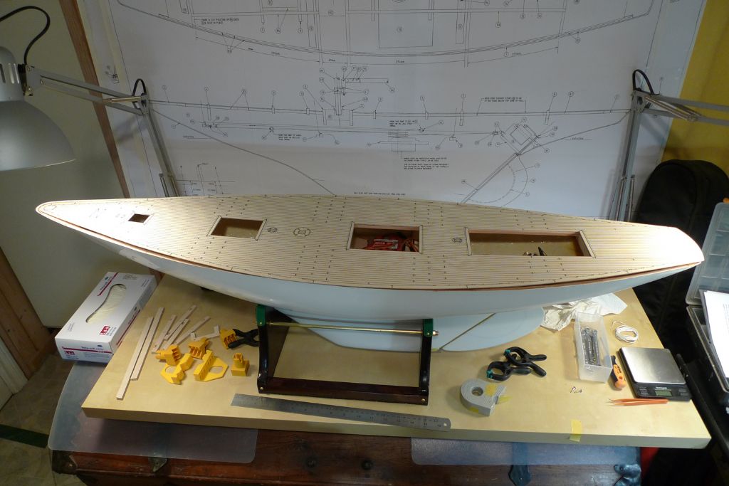
By the way, in the below photo, the deck has been laid in its correct position vis-à-vis the hull, and it is clearly visible that the beams are out by pretty much exactly a beam's width, i.e. 6 mm.
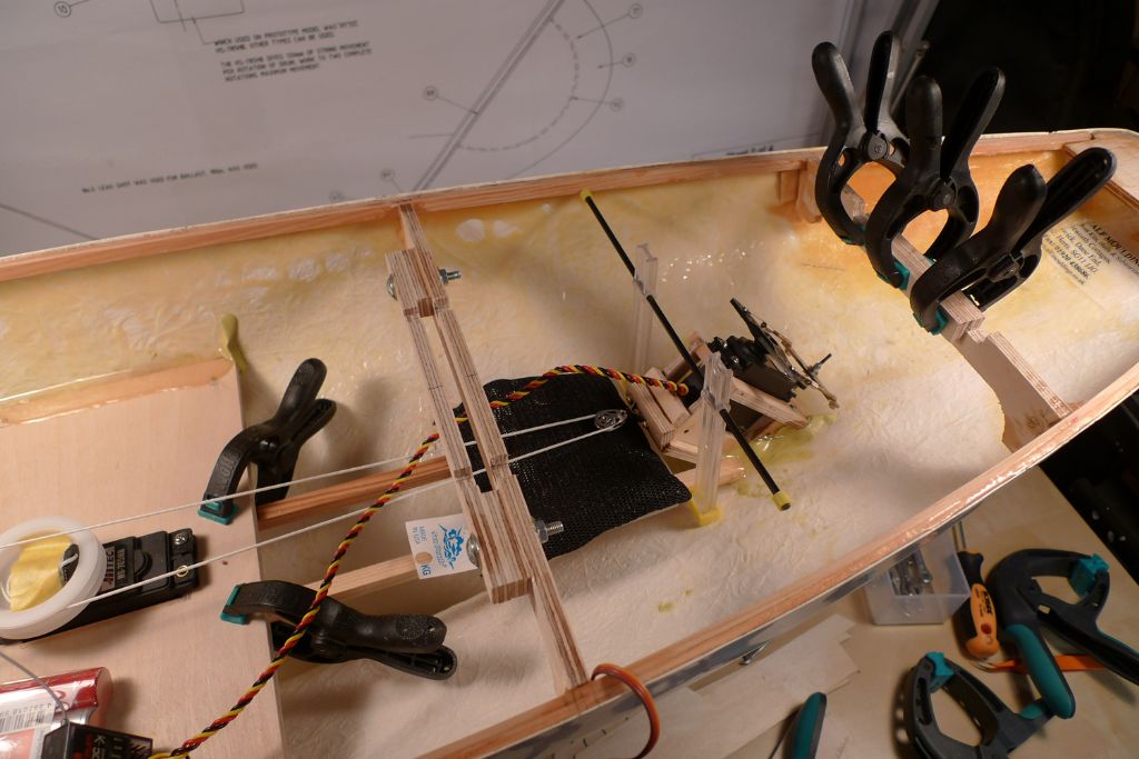
The cat that both beams were out by just that – a beam's width – then gave me my idea for a plan (d), which I adopted, namely to as it were move the central parts of both beams forward by 6 mm. The aftermost of the two was of course a very simple matter of just glueing on an additional piece of plywood taken from the offcuts of the CNC sheet whence came the beams in the first place.
As can be seen in the photo, I had by then also glued in the two stringers for the battery platform.
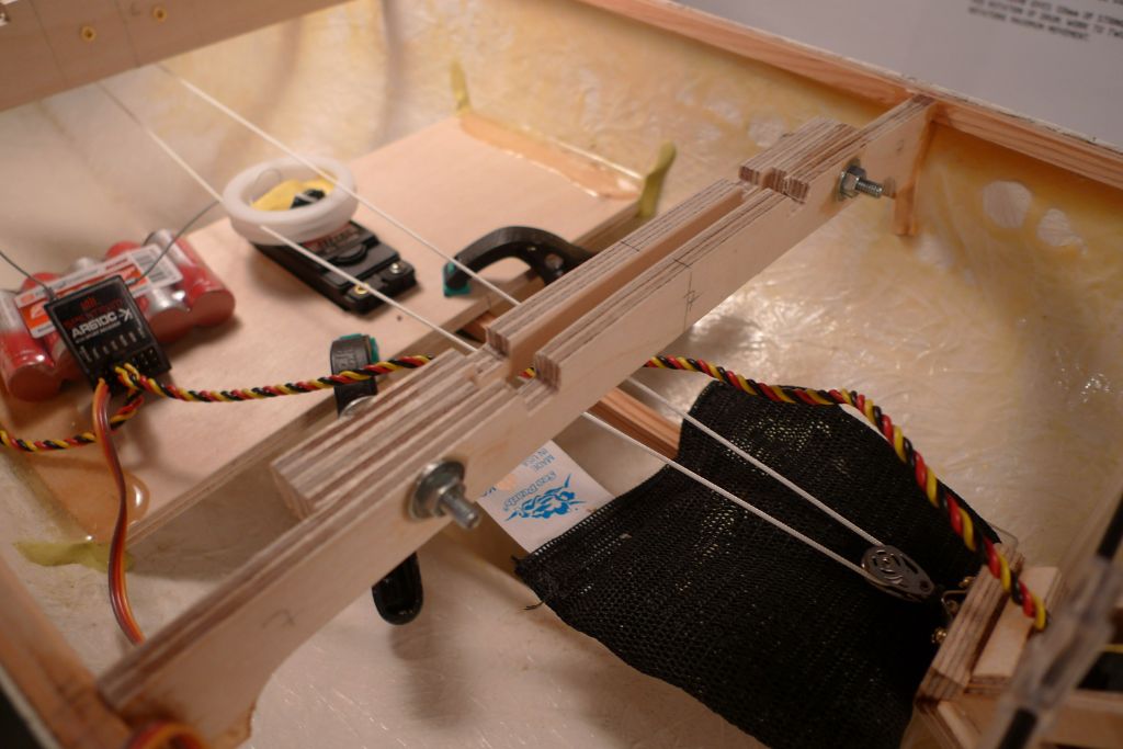
The forward beam, however, needed a slightly more complex operation, as the ensuing gap in the middle of the beam would have to be bridged. I was not keen on cutting first and bridging afterwards, as this would have meant both the risk of unwanted movement when the beam was cut and potentially tension built in if the new bridge was not fixed in place to absolute perfection.
To avoid these problems, I instead cut a suitable length of plywood for a bridge beam plus two smaller liner pieces. The liners were glued to the outer ends of the bridge beam and the ensuing sandwich drilled through. These drilled holes were then replicated on the original beam, and the whole thing joined together with epxoy but also bolted together with some M4 nuts and bolts for further strength.
Once the epoxy has gone off completely (i.e. later today) I shall cut through the original beam, and glue the cut-off central part to the aft face of the new bridging beam, thereby having moved the beam face 6 mm forrard.
To be continued …
/Mattias
5 June 2016 at 10:29 #65853Bob Abell 2
Participant@bobabell2That's a sloppy job! Banjo
I would think, the kit maker could remanufactue a new top?
Afterall, it's only a CAD drawing and a reprint would save the day
Even then, there's no guarantee, it would be a satisfactory job?
Personally, I would make a new top and plank to suit
Bob
-
AuthorPosts
- Please log in to reply to this topic. Registering is free and easy using the links on the menu at the top of this page.
Code of conduct | Forum Help/FAQs
Latest Replies
Home › Forums › Sailing Models › Topics
-
- Topic
- Voices
- Posts
- Last Post
-
-
Fairey Huntsman 31
1
2
…
5
6
Started by:
 Chris Fellows
in: Build Blogs
- 14
- 139
-
3 hours, 27 minutes ago
 Chris Fellows
-
Fairey Faun
1
2
3
Started by:
 Chris Fellows
in: Build Blogs
- 7
- 58
-
3 hours, 49 minutes ago
 Chris Fellows
-
Vic Smeed’s Silver Mist
1
2
…
32
33
Started by:
Bob Abell 2 in: Scratch build
- 4
- 822
-
4 hours, 28 minutes ago
 Tony Hadley
-
Fairey Huntsman 28
1
2
…
7
8
Started by:
 Chris Fellows
in: Build Blogs
- 1
- 195
-
5 hours, 57 minutes ago
 Chris Fellows
-
Eezebilt RAF Fire Boat
Started by:
Tim Cooper in: Build Blogs
- 2
- 3
-
6 hours, 32 minutes ago
 Dave Reed
-
Feathered Friends
Started by:
 Chris Fellows
in: Soapbox
- 3
- 7
-
9 hours, 39 minutes ago
 Chris Fellows
-
4D Modelshop
Started by:
Keith Long in: Scratch build
- 6
- 7
-
10 hours, 7 minutes ago
 Chris Fellows
-
John Cobb’s Crusader
1
2
…
7
8
Started by:
 Paul T
in: Scratch build
- 1
- 192
-
1 day, 5 hours ago
 John W E
-
Complex Automata
Started by:
 Colin Bishop
in: Soapbox
- 1
- 1
-
2 days, 8 hours ago
 Colin Bishop
-
RAF Fireboat ID
Started by:
 Dave Reed
in: Collectors’ corner
- 8
- 24
-
3 days, 9 hours ago
Tim Cooper
-
TID steam tug 42″ – PN Thomas drawing enlarged
1
2
Started by:
 Ray Wood 3
in: Scratch build
- 8
- 33
-
4 days, 3 hours ago
 Richard Simpson
-
Lady of Skye (puffer)
1
2
Started by:
 mick east
in: Build Blogs
- 9
- 43
-
4 days, 13 hours ago
 Richard Simpson
-
Building a hull.
Started by:
 mick east
in: Scratch build
- 7
- 10
-
6 days, 12 hours ago
 Ray Wood 3
-
Todays Boating
1
2
…
210
211
Started by:
 ashley needham
in: All things floating
- 84
- 5,252
-
1 week ago
 Colin Bishop
-
Sea Rover Restoration
Started by:
harry smith 1 in: Collectors’ corner
- 4
- 10
-
1 week ago
 Richard Simpson
-
WORKSHOP LIGHTING
Started by:
 John W E
in: All things floating
- 9
- 18
-
1 week, 1 day ago
 Colin Bishop
-
Mayhem Website Down
Started by:
 Colin Bishop
in: All things floating
- 4
- 10
-
1 week, 4 days ago
 Colin Bishop
-
MAGGIE M trawler
Started by:
 sammyk
in: Buy/Sell or Trade
- 2
- 3
-
1 week, 4 days ago
 sammyk
-
meter
Started by:
 Alasdair Allan
in: All things floating
- 5
- 16
-
1 week, 6 days ago
 Chris Fellows
-
River Queen 2”- 1’.
Started by:
Richard B in: Steam powered models
- 5
- 7
-
1 week, 6 days ago
Richard B
-
Deluxe Superphatic Glue.
Started by:
 Colin Bishop
in: All things floating
- 4
- 12
-
2 weeks ago
 Chris Fellows
-
How to add photos to your posts
Started by:
 Colin Bishop
in: Adding Images to Forum Posts
- 3
- 16
-
2 weeks ago
Len Morris 2
-
Cataract
Started by:
Bob Wilson in: Soapbox
- 2
- 4
-
2 weeks, 1 day ago
 Colin Bishop
-
The mighty tug Wattle
1
2
3
Started by:
 mick east
in: Build Blogs
- 10
- 61
-
2 weeks, 1 day ago
 Richard Simpson
-
Clyde Puffer Glenaray
1
2
3
Started by:
 Alasdair Allan
in: Build Blogs
- 6
- 57
-
2 weeks, 4 days ago
 Alasdair Allan
-
Fairey Huntsman 31
1
2
…
5
6
-


