The world's leading magazine for all model boating interests
Ballast Requirements (Boat Weights)
Ballast Requirements (Boat Weights)
- This topic has 46 replies, 7 voices, and was last updated 3 months, 2 weeks ago by
jcbryant.
-
AuthorPosts
-
7 January 2025 at 20:27 #124273
jcbryant
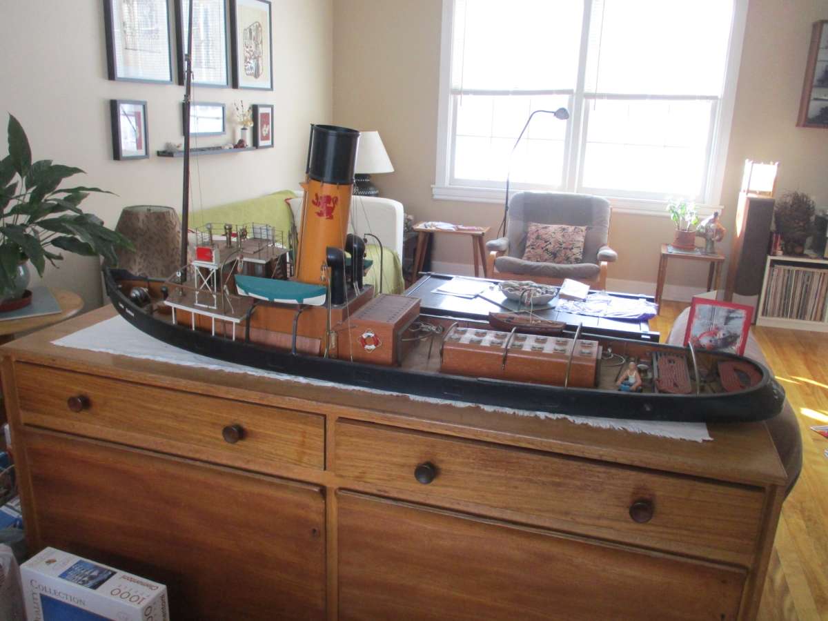
Participant@jcbryantI’ve acquired a 52″ model tug (first image). The funnel sports Caledonian Steam Packet Company colours and the port of registry is Irvine, but this is just because one of the two builders was Scottish, and she is called the Lady Sarah, but this is only because the other builder had a daughter named Sarah. Many will immediately recognize the tug as the Joffre.
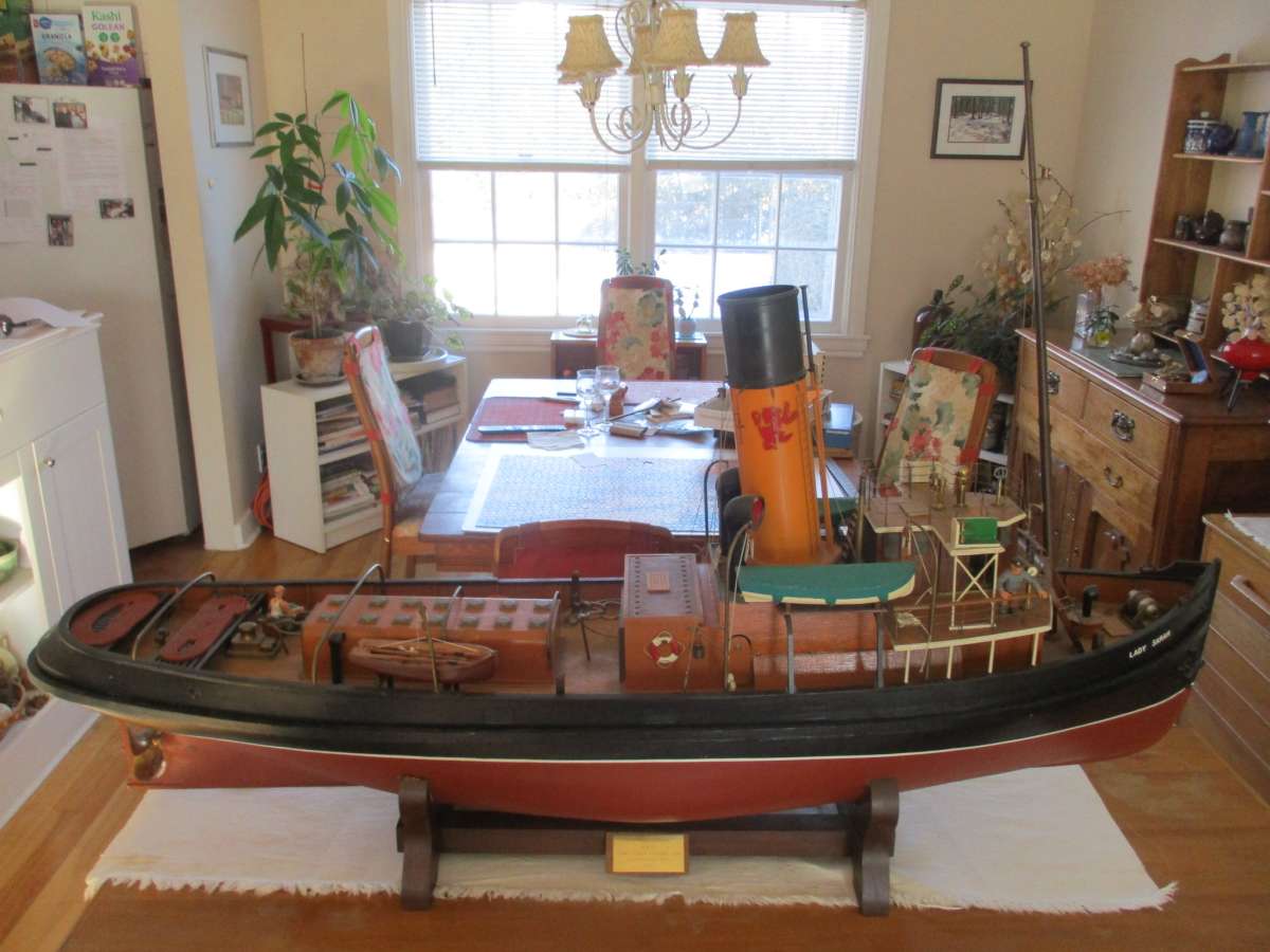
The builders obviously intended that the model be sailed. The tug came with a very nice double Stuart 10 and boiler installed on a test bed, and stringers sized to accept the engine were installed inside the hull. But that was basically it. For starters, the rudder was entirely cosmetic and as the stern was a solid block of wood, connecting the rudder to a servo was clearly left as a “future project”.
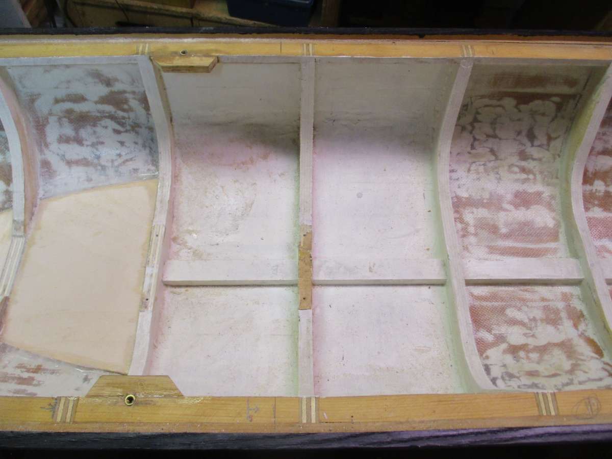
I’m now working on getting the boat in the water. Originally the (planked) hull was simply painted on the inside (central bays in the second photo). I’ve been working on lining the interior with fibreglass cloth impregnated with epoxy resin (right bay in the photo) and have also been filling in the bottom of each inter-rib bay (left bay in the photo).
The filling in is in part to give me a base on which to install things, but it’s also to avoid to have a lot of unconnected areas in which water can pool. I think the nature of the hull / superstructure joint is such that some water is bound to get in, and I want to have it collect in a single bilge where a pump can take care of it. The third picture shows where I’ve got to. The wood in a couple of the bays is not yet fastened down, but basically I’ve now a single contiguous “floor” with a bilge in the middle. The bilge covers two bays, but the aft portion of it is covered with a removable brass plate.
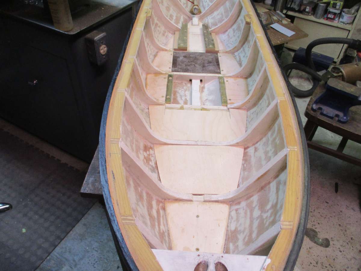
I’m going to start with an electric motor, but I hope to graduate eventually to the steam plant. Everything is being designed to accommodate both possibilities, and in particular I’ve mounted my electric motor in such a way that the bed to shaft distance is exactly the same as for the steam engine. The brass engine stringers visible towards the stern will therefore work for both engines. The next shot show the putative steam arrangement.
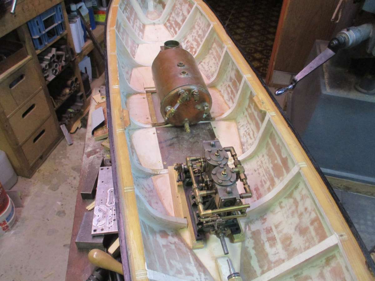
As a beginner, I’d like to know if I’m off track. And I’ve a specific question about ballast. As I’ve been filling in the bays, I’ve been placing a mixture of epoxy and scrap brass under the floor boards. My best estimate is that in order to float at the proper level, the model is going to have to weigh at least 70 lbs, and as it’s nowhere near that at the moment I reckoned that a modest amount of fixed ballast can’t hurt (though I certainly can see the advantages of mostly using removable ballast that is dropped in at the dock). Can anybody tell me what a 1:48 Caldercraft Joffre weighs when ready to sail? If I knew this number I could compute what my model needs to weigh in order to get in to float at the same waterline (just a matter of multiplying by the cube of the scale difference). Or, alternately, does anybody know what a Caldercraft Resolve weighs when appropriated ballasted? I’d expect my model to be very close as it’s about the same length and we’re dealing with two tugs.
I need a better feel for weight as I’m not sure whether I should cram as much weight as possible in the two bays that are not yet finished or whether I should fill them largely or entirely with wood.
Thanks in advance for any replies – John
8 January 2025 at 11:55 #124279 Colin BishopModerator@colinbishop34627
Hi John,
That’s a big model. It does seem that accurate model displacement weights are hard to come by. Those on the Caldercraft site are obviously wrong in many cases and probably the weight of the kit.
One way to tackle it would be to find a full size tug of around the same size as Joffre for which there are displacement details and scale down from the full size displacement. Cervia is almost the same size as Joffre and I have seen a reference to a displacement of 987 tons (see below). Cervia was one of the WW2 Empire class tugs and there is more information on these here:
https://www.rfaa-london.org.uk/app/wp-content/uploads/2020/02/RFA-history-11-RFA-Draft-Tugs.pdf
Deans Marine do a kit of Empire Susan which mentions the displacement of the original as 987 tons.
https://deansmarine.co.uk/shop/product_info.php/products_id/2439
Around 1,000 tons for Joffre might be a working figure.
Colin
8 January 2025 at 13:16 #124281jcbryant
Participant@jcbryantColin,
It is a big model – larger than I would have chosen if starting from scratch. The model’s length and beam imply slightly different scales, but both are close to 1:26. I’m guessing that the scale was selected so that the double Stuart 10 would fit.
Taking the length, beam, and draft of the model and multiplying by the density of water gives a displacement of 108 lbs. The actual displacement has to be less than this because, boxy as the hull may be, it isn’t a a rectangular box, especially towards the stern. So perhaps something around 75% of 108 lbs = 80 lbs.
Working from a displacement of 1000 (presumably long?) tons for the full sized Joffre gives a much higher figure. 1000 x 2240 / (26^3) = 127 lbs. If one assumes that 80 lbs for the model is correct, the full size displacement must have been just 630 or so tons.
Probably the correct figures lie somewhere between these two extremes.
It is frustrating that while advertising for kits invariably gives the length of the completed model, weights quoted do seem to generally relate to the box that the kit will arrive in. The only exception that I’ve come across is that one vendor specified 19.5 kg for the Caldercraft Joffre. This clearly isn’t right, but if one assumes lbs rather the kg then the implied weight for my model is 19.5 lbs x (48/26)^3 = 123 lbs, which at least is the right ballpark.
– John
8 January 2025 at 14:34 #124292 Colin BishopModerator@colinbishop34627
John, Can you not remove the superstructure and float the hull in the bath or a suitable container and add weights until it is down to its marks? Then weigh the hull and weights to get the overall displacement.
Next weigh the boat dry with the superstructure on and deduct that from the overall displacement and the difference will be the weight of the power plant, internal fittings and radio plus the remaining ballast needed. (I think I’ve got that right!) This is what a lot of us do.
Colin
8 January 2025 at 15:11 #124294 Richard SimpsonParticipant@richardsimpson88330
John, I’m with Colin on this. I wouldn’t get wrapped up in playing around with numbers as there are so many variables involved and so many assumptions that you can end up getting lost in it all. For instance who is to say that 75% is a reasonable block coefficient for a tug hull? At the end of the day putting the model in the bath and having a play is the only way to get somewhere near to where you want things.
I understand where you are coming from as you need a total ballast requirement if you are looking at using two totally different propulsion systems in the same hull. Consequently I would play around in the bath by adding weights internally then putting the superstructure back on and see how she sits. When you have her sitting correctly and she has a suitable righting moment then you know what weight you have available to play with. By suitable righting moment I mean you need to push the top of the mast over and see how quickly she returns to upright when you let go.
All the components you need to add for whichever propulsion system you are considering must then be weighed and subtracted from the total ballast to give you a ballast figure for each propulsion system. I tend to then spread this ballast along the length of the hull, even sometimes just putting half at either end to prevent the ends bobbing up and down in an unrealistic manner.
As an example I have a 1/48th scale Graupner Corvette. The instructions said it needed 6kg total ballast. I got all the bits together I was going to put into it, receiver, smoke generator, 6v propulsion battery, 12v smoke generator battery etc, and weighed it all, which came to around 2kg. These component were spread along the length and I put 2kg of lead shot in the bow and 2kg in the stern. She sat perfectly in the bath and had a good righting moment so I fixed the shot with resin.
I would try a similar approach.
8 January 2025 at 16:11 #124296 Richard SimpsonParticipant@richardsimpson88330
If it is any help I have just weighed my own Caldercraft Joffre and she weighs in at 5.82kg. Having said that she does sit a little on the low side so she could be a little lighter. I didn’t build it though and while I have removed a couple of sheets of lead from the bottom I can’t get the last one out!
8 January 2025 at 18:55 #124298jcbryant
Participant@jcbryantBathtub testing is definitely part of the plan, especially with regards to getting the trim right.
But the immediate question is simply whether I can afford to add more permanent ballast in the course of fleshing out the interior. As per Richard’s comments, bits of brass epoxied in place under the floorboards are not something that can easily be removed!
Richard’s 5.82kg weight for his Joffre is exactly what I’ve been looking for. Adjusting for the scale difference, my model should come in at around 5.82 kg x (48/26)^3 = 36.6 kg = 80.6 lbs. Which is very credible indeed as it fits very nicely with my estimate.
But I definitely don’t want my model to sit on the low side. The picture below shows the superstructure. It sits on the hull rather like a lid sits on a saucepan. This arrangement makes the interior of the hull very accessible, but also gives a very long joint that cannot easily be sealed, and the effective freeboard midships doesn’t amount to very much.
So I’d like my tug to float as high as possible within reason. On the rectangular box principle, getting the waterline 1/2″ higher than where it is on Richard’s Joffre means reducing the total weight by about 10 lbs. So I’m looking at a total weight budget of about 70 lbs.
The superstructure weighs 9.2 lbs and this isn’t going to change. With the entire steam plant and various ancillaries (e.g. propane tank, burner, water pump, etc.) aboard, and with the boiler filled to operating level, the hull weighs 31 lbs. Allowing for another 10 lbs or so of necessary fittings (receiver, batteries, bilge pump, etc.), these means that I’ve still about 20 lbs to go and can therefore bury at least a bit more ballast where it’s most effective from a stability point of view. As both of the remaining bays are towards the bow, however, I will do a bathtub test to ensure that the tug isn’t in danger of becoming bow heavy.
Thanks very much for the input – John
9 January 2025 at 20:50 #124306jcbryant
Participant@jcbryantThere is one little issue with bathtub testing. It’s close, but the model is unfortunately a bit too long to fit in our bathtub.
I’m getting a lesson in why larger models are perhaps not such a good idea. Any future projects are definitely going to be smaller!
– John
9 January 2025 at 22:26 #124307 Colin BishopModerator@colinbishop34627
Yes I had that problem, ended up with a cheap paddling pool in the garden! I agree larger models look good on the pond but do pose practical problems.
One of the kit manufacturers I knew had a rule of not making a model that could not be fitted across the back seat of a standard car. Very sensible really.
Colin
18 January 2025 at 08:26 #124371 Ray Wood 3Participant@raywood3
Hello John,
I’m sorry to be late to this thread, I’ve had the flu for a week 🙁
Nobody seems to have mentioned how un sea worthy your tug is !! with the low freeboard of a tug anyway and the join of deck and hull being only an inch above the water, As she is going to be 60 lbs + boat the watertightness is vital otherwise you will have a very heavy submarine ?? with that boiler and double 10 on board.
The answer will be to prise the superstructure of the deck and make suitable access hatches to the steam plant and glue the deck and bulwarks to the hull, this will give you a much better chance of staying afloat 🙂
My 39″ Cullamix tug took 25 lbs of old iron castings, with an all up weight of 35 lbs.
Launching and recovery is also something to consider ?
Regards Ray
18 January 2025 at 12:55 #124373 Colin BishopModerator@colinbishop34627
I rather doubt if detaching the superstructure is going to be a practical solution given the amount of work and risk of damage but the boat is certainly going to be vulnerable to taking on water. Just raising the waterline a bit won’t be enough as a tug model moving through the water will create waves which will reach up to deck level along the hull.
There are a couple of ways you can mitigate things to some extent. It might be possible to establish a silicone gasket along the joint which, if not totally watertight, would significantly reduce the inevitable inflow. I think Ashley did this with one of his recent models.
Secondly, you could use some of that ballast weight to fit a miniature automatic bilge pump and a 12v gel cell battery. The outflow can be led through the side of the hull where it will be easily noticed.
I do find it difficult to understand how the original builder could have made such a serious design error which throws into serious doubt the viability of the boat as a working model. Maybe that is why it was never finished or run? It wouldn’t have worked without a rudder either and the design has made fitting one almost impossible as on this sort of full size tug the rudder post would emerge on deck under the grating at the stern where it would be attached to a quadrant tiller. Chains from this would be led along the inside of the bulwarks and up into the wheelhouse. On a model it is sometimes possible to have a pushrod along the deck to a servo under the engine room skylight. But if you try to do this then you won’t be able to get the deck off without dismantling it all, not practical with a steam powered model at the pondside.
Your photos do not show the stern with the top off but the only possibility to fit a rudder in the circumstances would be to excavate the solid wood underneath the deck sufficiently to install a rudder tube with a tiller which can be connected to a servo placed further forward in the hull. This would be similar to what I am doing on my current liner model – see photo.
Having looked the the photos in more detail I’m not a all sure that you can turn this into a working model even if it was the original intention of the builder.
Colin
 18 January 2025 at 14:56 #124379
jcbryant
Participant@jcbryantI completely agree that the arrangement isn’t very seaworthy. The effective freeboard is only about 1-3/4″, and the fact that the superstructure fits inside the hull rather than sitting over it means that any water that gets into the joint area is going to drain into the boat rather than back into the pond. It is indeed not hard to imagine that the reason the builders didn’t complete their project is that at some point they were told that the whole arrangement wasn’t practical.
But at this point major surgery isn’t very practical either. So the choice is between simply leaving the model on a shelf and making the best of the way things are. Given how heavy the tug has to be, there simply isn’t enough free interior volume to guarantee positive buoyancy by installing foam and/or air bags. I have thought that perhaps some of the ballast could be in the form of water tanks that would be blown empty by CO2 cartridges in the event of the hull flooding. This plus filling every nook and cranny with foam might just do the trick, but it would obviously be a major exercise.
In practical terms I think that I’m looking at i) doing what I can with the joint and ii) installing a bilge pump. Ideally the joint would involve a massive O-ring, and if I were starting from scratch I think that this would be an eminently practical proposition. But this approach requires well fitting surfaces and a groove in one of them, and at this point I don’t think that either of these requirements is achievable. In practice I think that my best option is to clean up both surfaces, coat the superstructure with wax, and then assemble the hull and superstructure with the joint area covered with epoxy. This should at least ensure a good fit and (hopefully) prevent more than a modest amount of water getting in. On the bilge pump front, I’m looking at https://www.amazon.ca/gp/product/B09XH1GYYQ. I reckon (hope) that some attention to the joint should keep the inflow of water below 1.3 litres a minute, especially if I limit myself to calm days and avoid having an unrealistically large bow wave.
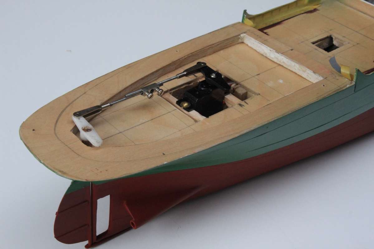
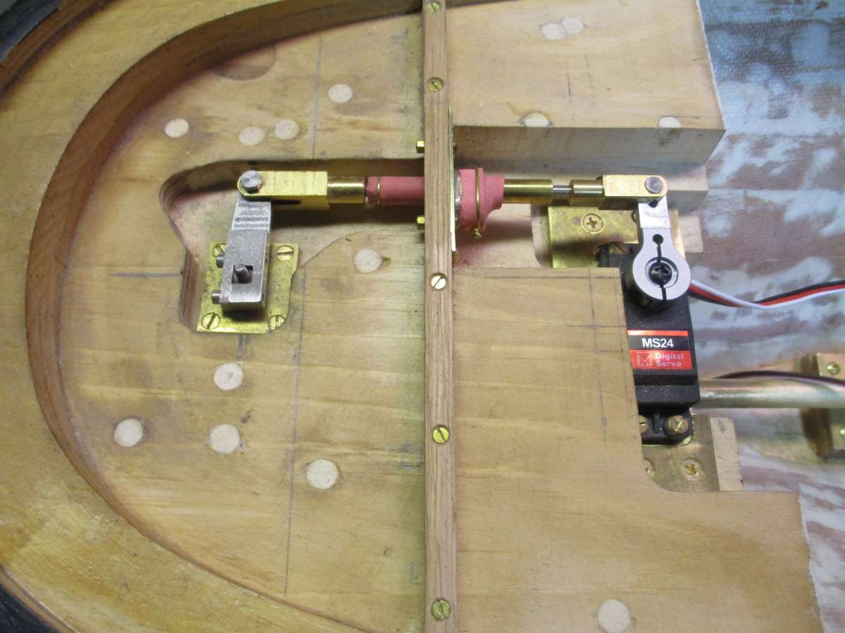
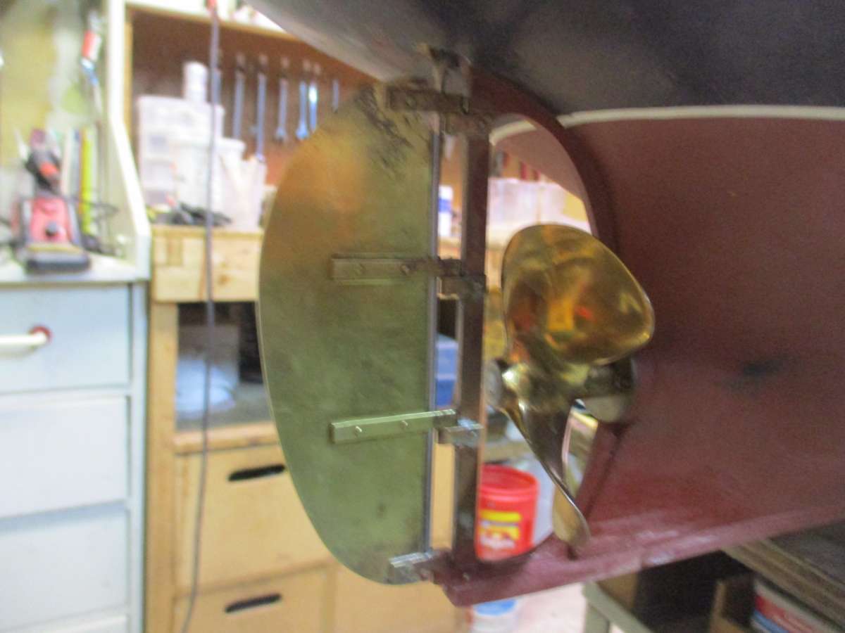
At least the rudder issue has been dealt with. I’ve routed out areas of what was a solid wood stern and have installed a rudder linkage and servo. There’s an O-ring seal below the brass plate around the top of the rudder post, and I like to think that it would prevent any water getting in even if it were below the waterline. But to be safe I’ve installed a rolling seal on the linkage as well. It would do the trick even if the rudder post was totally unsealed and the area around it was effectively on the outside of the hull.
And I’ve made a totally new rudder with much more substantial gudgeons and pintles. Unfortunately I made it before reading that model rudders typically need to to larger than scale to provide reasonable turning circles (a real shame as I could easily have added a bit of area without significantly affecting the cosmetics). Time will tell. If performance is indeed unsatisfactory I can make a bolt on rudder extension, and in extremis I can simply make a somewhat larger rudder. I take some comfort in a remark to the effect that the need for larger rudders applies less to tugs than other vessels, and in the fact that the area of my rudder does meet the criteria suggested by another writer.
– John
18 January 2025 at 15:56 #124381 Colin BishopModerator@colinbishop34627
Very glad to see you have fixed the rudder issue, a neat solution and exactly what I had in mind.. You may find that the size is OK as it is directly behind the prop. Some people who have rudder problems have made ‘slip on’ extensions which can be removed when the boat is out of the water. If made with transparent plastic they are pretty much invisible when the model is afloat too.
I have messaged Ashley Needham to have a look at this topic to see if his ‘made to measure’ gasket idea would work for you. Could be more effective and less messy than your wax/epoxy idea.
Colin
19 January 2025 at 09:46 #124383 ashley needhamParticipant@ashleyneedham69188
Message received and understood!
Colin is referring to a yet undisclosed build which has the same issue of inadequate freeboard. I did post on this I think on today’s boating a while back.
Basically, what did was clingfilm the hull top and upend it over the deck, then fill in the gap with a HIGH MODULUS silicone sealant. I pulled the parts apart and then had a collar that was a really good fit over the hull top.
You have not quite got the same setup but it’s near enough. Cling film the hull, pipe high modulus silicone onto the rim underside the top and put it in place. Wait 24hrs to fully cure and you should have the best possible seal between hull and top. The silicone should stick to the top and the clingfilm will allow the hull to release. Perhaps a smear of vasalene under the clingfilm will help the release…as the clingfilm may stick to the silicone. Will/might need trimming, and I found an Anthracite grey silicone and this will match the black paint ok.
You have to be brave with this one…all or nothing.
Rudder..I always over rudder mine. Easy to trim if not needed but difficult to add more area. My Titanic rudder is probably three times the scale size and is only just adequate…..
Ashley
19 January 2025 at 10:42 #124389 Richard SimpsonParticipant@richardsimpson88330
Just adding a couple of thoughts to the mix to either chew over or spit out!
First I have to say your rudder connection is beautifully done and such a perfect example of how a ca
refully thought out and well executed solution can be used to solve a problem.
OK, the challenges, I’ve seen sticky backed closed cell foam edging used as a seal in the past. They type that used to be used to seal poorly fitting doors and windows before everything went double glazing. Not elegant but fairly successful depending on the gap. It needs compressing though. I’ve also seen a smear of Vaseline used, again it depends on the size of the gap.
I just want to put a couple of probably more controversial thoughts out there. First up I built a steam model over a twenty year period, see Model Boat Magazine Boiler Room articles in Editions Nov and Dec ’24 and Jan ’25, and had to come to the conclusion that it simply wasn’t seaworthy enough to risk it on the water. She sits at the correct waterline, which is too low for a scale model, and contains a huge amount of expensive plant. Not to mention the time, effort and love that has gone into its creation. Consequently I am simply not prepared to take the risk and she now sits in a glass cabinet. I saw it as a failure for some time, as did a number of friends who said I should give it “just one outing”, but I knew it was a risk I didn’t want to take. To get the weight down would be a major disassembly and rebuild, which I am also not prepared to take on. Now however I don’t see it quite so much as a failure, more of a big part of my own learning curve as a modeller. I enjoy seeing it in the glass case and it will now outlast me, god knows where. The only point being, it is an option to decide not to sail the model.
Having said that I also have a Model Slipway Envoy Class tug. She sits very low aft and has a more normal arrangement of a sealed deck edge and access hatches over coamings. Even with a very low aft freeboard I get very little water on deck as a result of only using it in appropriate conditions, i.e. flat calm day and take it out when the lifeboats go on the water!
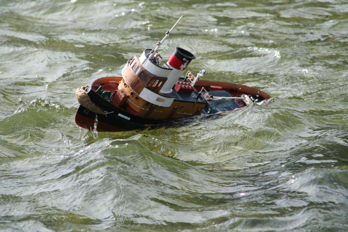
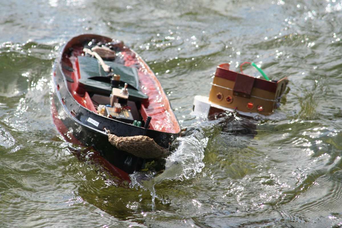
The final thought I can offer is the fact that I’ve only ever had one model sink on me. Yes, it was my Caldercraft Joffre. Luckily I retrieved it, refurbished it, repainted it and still use it but it is a reminder that it can happen. I did read somewhere that she was conscripted into navy service at one point so I went for a RN colour scheme.
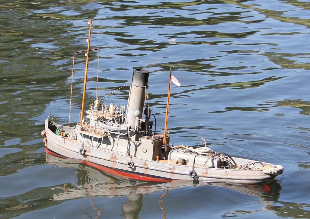
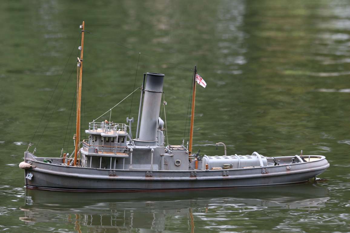
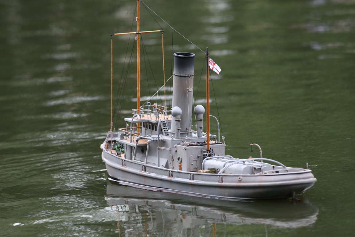
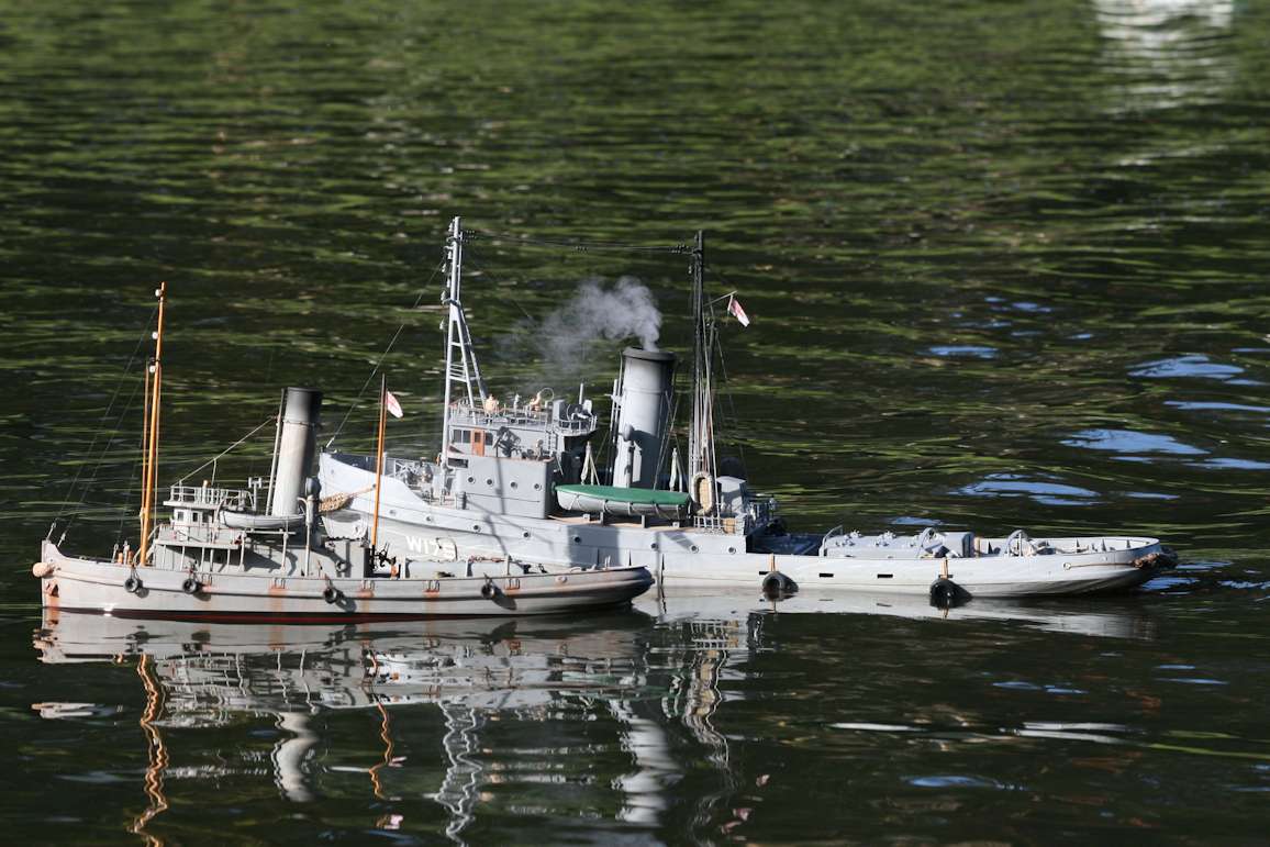 19 January 2025 at 11:23 #124395
 Colin BishopModerator@colinbishop34627
John, are you sure you can’t go for the DiY ‘O’ ring solution? You can buy nitrile rubber ‘O’ ring cord in various diameters from around 1mm upwards for peanuts and it can be glued very well with cyano. It’s black too!
Colin
19 January 2025 at 13:50 #124399 Colin BishopModerator@colinbishop34627
Extra question, what keeps the top secured to the hull so that it doesn’t get knocked off?
Colin
 19 January 2025 at 15:36 #124401
jcbryant
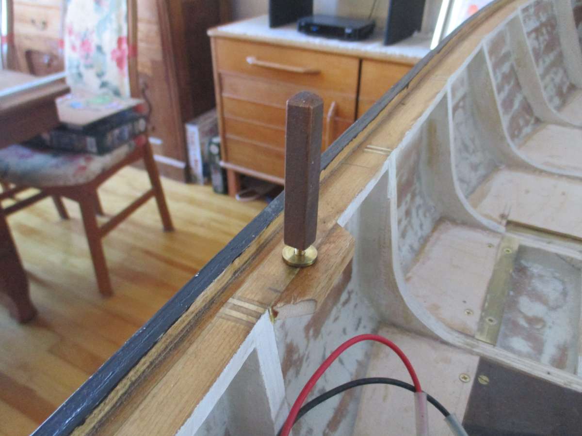
Participant@jcbryantFirst on all, an extra answer to the extra question. The top portion is secured to the hull by two screw in snubbing posts. The picture shows one of these in situ but without the top portion.
Thank you Ashley for the silicone idea. It’s brilliant. Conceptually not that far removed from epoxy and wax, but ever so much more practical, and I like the fact that silicone is much more flexible/resilient than epoxy. I’m not familiar with the idea of high modulus silicone, and it may well be called something completely different out here in the colonies, but I’m sure that I can work this out.
I’ve absolutely no faith in the precision of the hull/superstructure joint as it currently exists. Rather I’m pretty sure that while the hull and superstructure have to touch each other in places, there are also areas where they are some distance from each other. The picture below, for example, shows an area where there is a significant dip in the hull. Some of this is due to the sheer at this point, and in principle the top portion could have a perfectly matching bulge, but I’m sure that the reality is that I’m simply not dealing with a very precise piece of work.
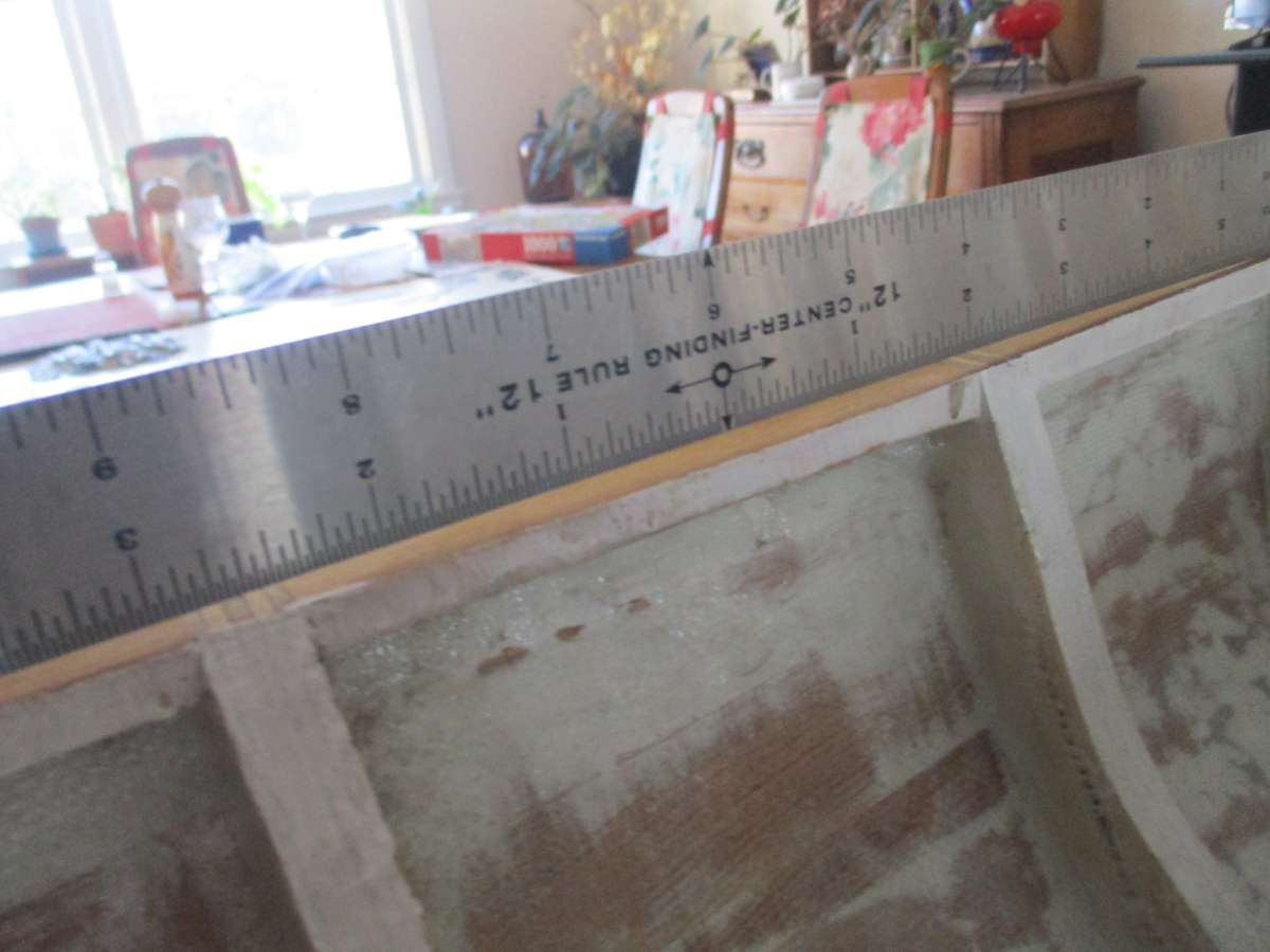
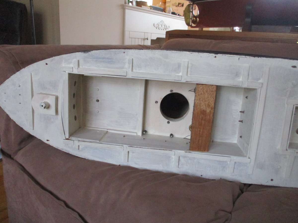
The next pictures show the underside of the superstructure. It’s clear that I’m dealing with a rather rough and ready piece of work rather anything close to a precise watertight fit. In the second shot the bottom of a davit can even be seen protruding into the critical area, and there are other such protrusions elsewhere. Filing these flush is an obvious first step. The fact that the bottom of the funnel is open is a sign that it was indeed intended to use the steam plant, and the ventilators are also functional. But the boiler room crosswalk (visible if one opens the doors at either end of it) is a bit strange in that it pretty well precludes installing the boiler. The boiler does fit below it, but however things are arranged the crosswalk is bound to foul either the safety valve or the steam turret. Probably things weren’t completely thought through.
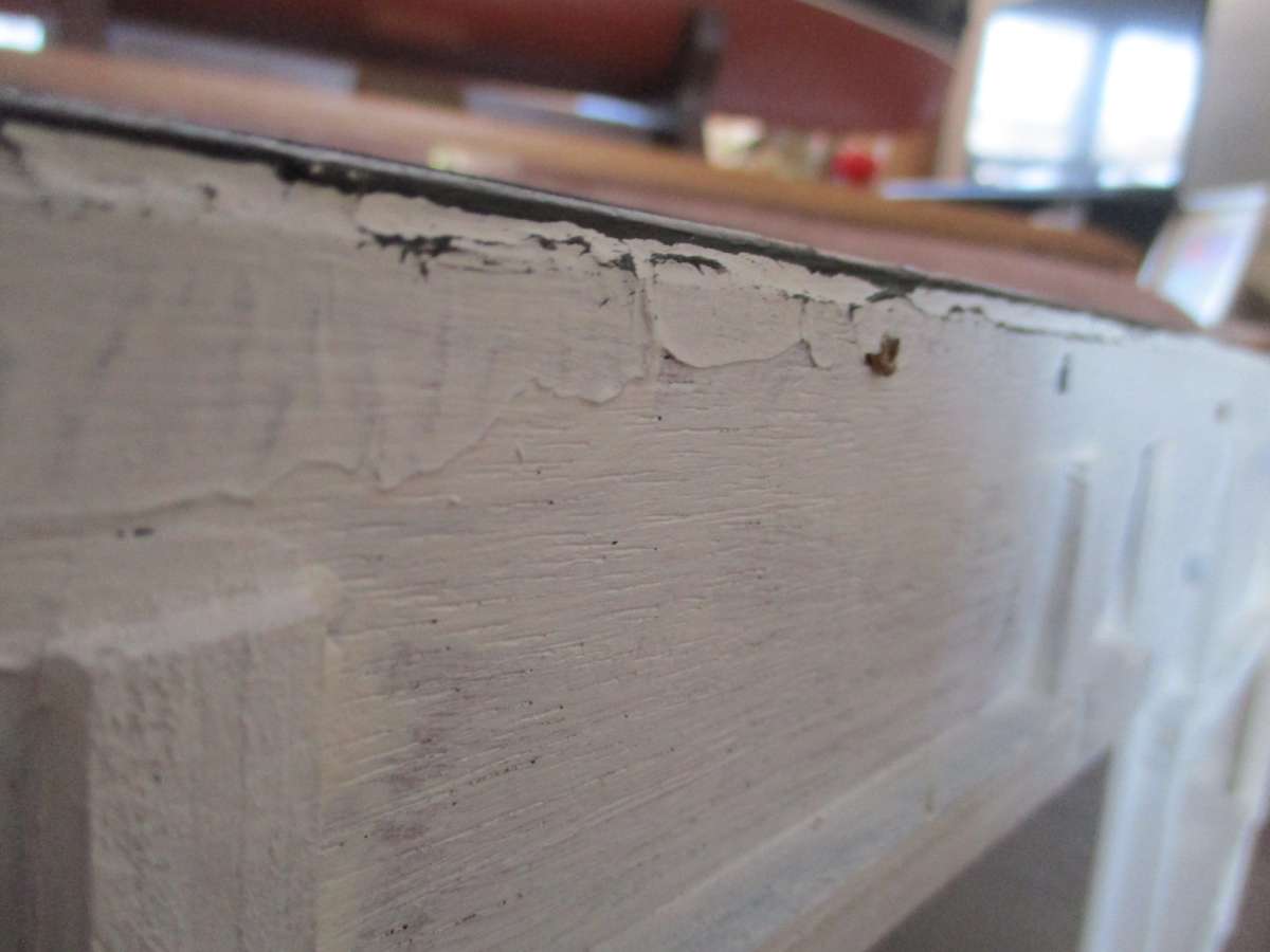
In this case I think that an O ring is a non-starter because there would be areas where the ring was over compressed and spots where it wasn’t compressed at all. I can see, however, that an O ring might work very well given a hull constructed using the bread and butter method. One would simply stop at some point, use a router to put a suitable groove in the top layer, and then screw the next layer in place before proceeding with additional layers (making sure, of course, that the screw heads remained accessible!). At the end of the day installing O ring material in the groove would in principle result in a perfectly watertight seal between the lower and upper parts of the hull.
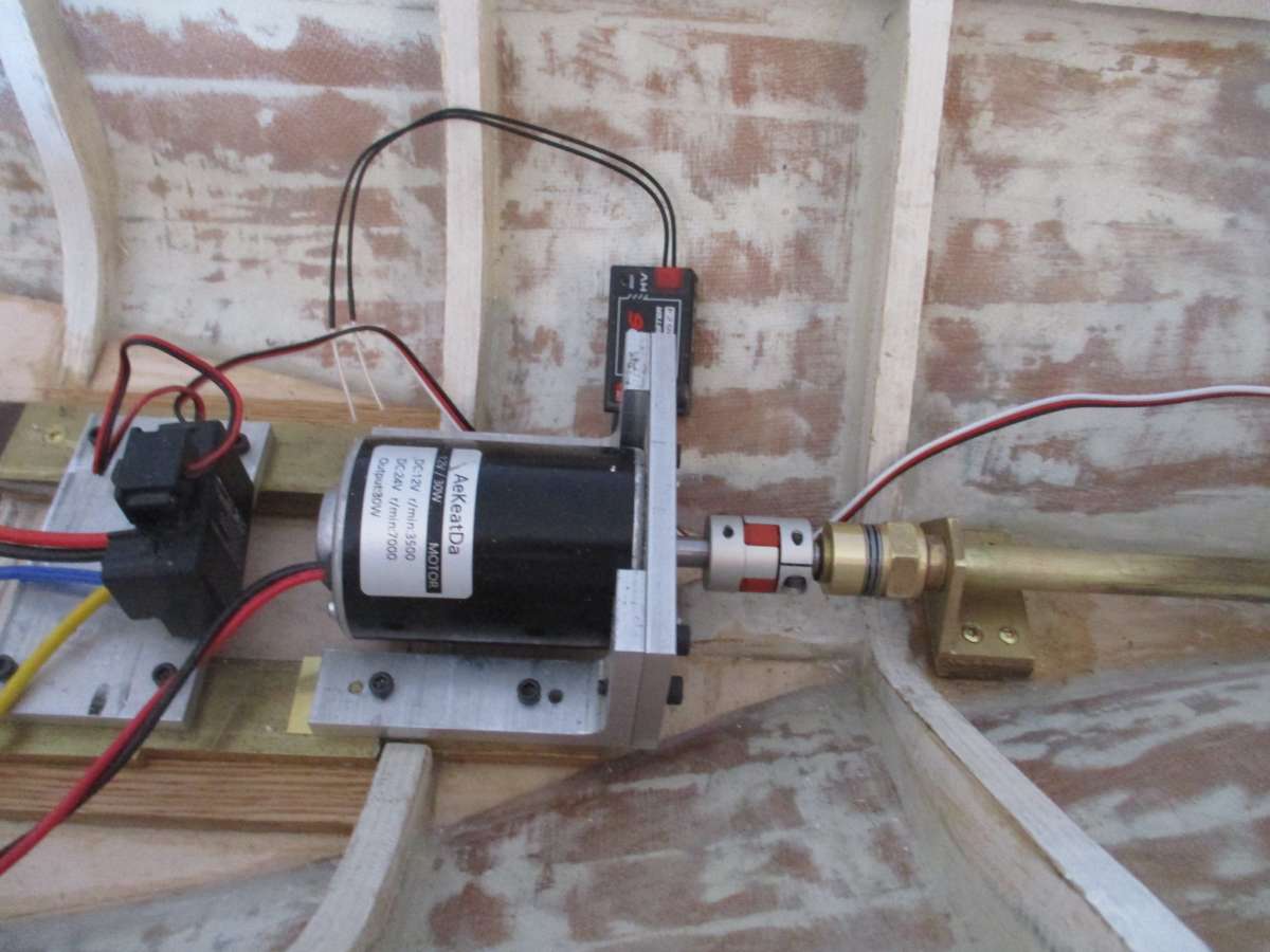
The points made about the problems inherent in using a steam plant are well taken. I’m definitely starting off with electric power and a motor is now installed. The picture illustrates a few other things that needed to be looked after if this tug was ever to reach the pond. The inner end of the stern tube was originally totally unsupported and lacked any form of stuffing box. I’ve added a supporting bracket, and there’s now an O-ring seal. Inboard of the hex nut that creates the O-ring cavity there’s a thrust bearing and a collar on the propeller shaft. These look after longitudinal forces when running astern and prevent the propeller from pulling the shaft coupling apart. The collar is secured to the shaft by a set screw, and to provide extra security there’s also a retaining ring on the inboard side of it.
Using the steam plant does promise to be a major challenge, but then I enjoy meeting and overcoming challenges. I really would like to make some use of the plant, and short of building a really large open launch (which I agree would be a more practical proposition), this tug is my best option. Sadly the plant is too big to fit in anything much smaller (which is probably why the tug is as large as it is).
19 January 2025 at 16:10 #124402 Colin BishopModerator@colinbishop34627
Looking at the latest photos I would agree that Ashley’s method is more likely to compensate for the irregularities. It’s a mystery why the original builder chose this method of construction as tugs are popular subjects for steam power because it is relatively easy to incorporate large hatches with coamings under the superstructure and engine room skylights to facilitate access to the interior. A permanently attached deck also greatly strengthens the structure.
Colin
19 January 2025 at 16:58 #124404 Ray Wood 3Participant@raywood3
Hi John,
Your standard of workmanship is obviously excellent with good equipment 🙂
In the short term as an electric boat the fixed down lid is fine, probably only needing to be removed for battery charging , but if the long term aim is to run her with the steam plant you will need to do a proper job and re-build the new deck with access hatches upstands and bulwarks insitu, it will save a lot of frustration in the long run, I’m sure the existing superstructure & bulwarks can be re-used, you will need maximum access for gas and water and pressure gauge levels lubrications etc the lift off superstructure is the only practical way of achieving this.
Has the boiler got a return flue in it ? its not a standard centre flue boiler !
I’m in a similar situation having aquired a steam plant but I’m going to make a new boat around it 🙂
Regards Ray
19 January 2025 at 17:55 #124406 Richard SimpsonParticipant@richardsimpson88330
Having tried both I am nowadays firmly of the opinion that steam plants are infinitely easier to build, maintain and operate in an open hull. Plus you get to see it all operating!
19 January 2025 at 18:58 #124409jcbryant
Participant@jcbryantWhen I first acquired the tug I did a bit of research on steam plants in RC models, and one of the first things I read was that boats with steam engines are almost invariably open launches, and that enclosed steam plants are both unusual and “difficult”. And I’ve absolutely no trouble in understanding why this is so.
Unfortunately I think that an open launch would have to be at least 6′ long for the plant I’ve got to look right. Unlike tugs, launches are normally not given over largely to the boiler and engine. Some space for passengers is a key part of the concept.
The boiler is a simplified Scotch boiler (one with just two largish tubes). In my case I think that it makes sense to have the burner (and hence the exhaust) at the front end. This doesn’t fit very well with the location of the funnel, and a cranked uptake is going to be required.
If both the superstructure and the engine casing were made removable, it might just be possible to arrange the steam plant so that everything that needs to be got at on an everyday basis was accessible via these two openings. But things would be very tight indeed, and coming up with a satisfactory arrangement (e.g. one that makes it easy to both light the burner and see the boiler sight glass) might in fact be impossible. And one would still need the current joint (though is could be filled with a non-hardening sealant and kept screwed together most of the time) as otherwise maintenance would be well nigh impossible. In view of all this, my current feeling is that simply making the existing joint into a practical proposition (together with good bilge pump!) is probably the best option.
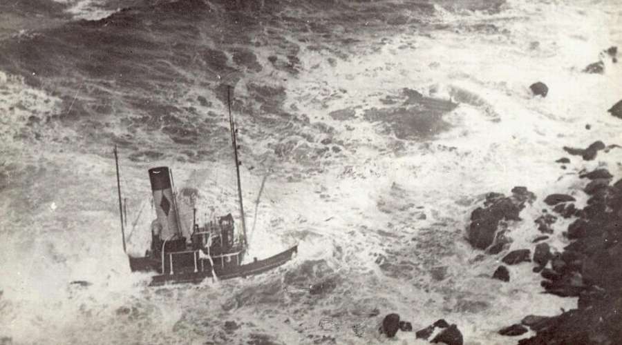
Re Richard’s previous comment that the only boat he has ever had sink was Joffre, this is in way very appropriate, as the full-sized Joffre also had a narrow escape. As many will perhaps know, she ran around in fog at one point fairly early on in her life, and looking at the pictures it’s amazing that she survived the experience.
 19 January 2025 at 19:37 #124410
 Colin BishopModerator@colinbishop34627
I’m not sure that steam models are invariably open launches, over many years I have seen plenty of models where this is not the case and the steam plant is below decks. Inevitably this introduces more complexity but this is not always a problem if the model is designed with adequate on deck access to the power plant at the outset and has sufficient ventilation. Not necessarily ‘difficult’, just a matter of choice and getting the initial design right.
As Richard says, open launches are more straightforward and easier to build, plus have you have the bonus of seeing it all operating and that is a big attraction to both modellers and observers. With enclosed steam plants you just see the plume from the funnel. Horses for courses really. It’s always great to watch a steam engine in action whether it is in a model or full size as in a preserved pumping station or a paddle steamer like ps Waverley.
It has been said that a steam engine is the closest thing man has created to a living and breathing object.
Colin
20 January 2025 at 11:29 #124422 Colin BishopModerator@colinbishop34627
I’m not familiar with the idea of high modulus silicone,
Modulus refers to the degree of elasticity when cured. High Modulus is firm, Low Modulusm is flexible and more tolerant of movement between surfaces such as when sealing around a bath for example. A gasket, as described by Ashley, is better if firm.
Colin
20 January 2025 at 12:04 #124424 ashley needhamParticipant@ashleyneedham69188
It was Len who suggested the High Modulus sealant..i had never heard of it before. You have to look at all the technical specs of various silicone sealants and it should state there what they are.
Marine silicone might be another source, from a boatyard. These are much tougher than kitchen types…I have used two lots over the years. One of them was used to stick the top and bottom bits of my MFA Fantome together.
Ashley
-
AuthorPosts
- Please log in to reply to this topic. Registering is free and easy using the links on the menu at the top of this page.
Code of conduct | Forum Help/FAQs
Latest Replies
-
- Topic
- Voices
- Posts
- Last Post
-
-
RAF Fireboat ID
Started by:
 Dave Reed
in: Collectors’ corner
- 8
- 24
-
50 minutes ago
Tim Cooper
-
TID steam tug 42″ – PN Thomas drawing enlarged
1
2
Started by:
 Ray Wood 3
in: Scratch build
- 8
- 33
-
18 hours, 15 minutes ago
 Richard Simpson
-
Lady of Skye (puffer)
1
2
Started by:
 mick east
in: Build Blogs
- 9
- 43
-
1 day, 4 hours ago
 Richard Simpson
-
Fairey Huntsman 31
1
2
…
5
6
Started by:
 Chris Fellows
in: Build Blogs
- 13
- 130
-
1 day, 18 hours ago
inonowt
-
Building a hull.
Started by:
 mick east
in: Scratch build
- 7
- 10
-
3 days, 3 hours ago
 Ray Wood 3
-
Todays Boating
1
2
…
210
211
Started by:
 ashley needham
in: All things floating
- 84
- 5,252
-
3 days, 17 hours ago
 Colin Bishop
-
Sea Rover Restoration
Started by:
harry smith 1 in: Collectors’ corner
- 4
- 10
-
3 days, 19 hours ago
 Richard Simpson
-
WORKSHOP LIGHTING
Started by:
 John W E
in: All things floating
- 9
- 18
-
4 days, 17 hours ago
 Colin Bishop
-
Mayhem Website Down
Started by:
 Colin Bishop
in: All things floating
- 4
- 10
-
1 week, 1 day ago
 Colin Bishop
-
MAGGIE M trawler
Started by:
 sammyk
in: Buy/Sell or Trade
- 2
- 3
-
1 week, 1 day ago
 sammyk
-
Fairey Huntsman 28
1
2
…
7
8
Started by:
 Chris Fellows
in: Build Blogs
- 1
- 194
-
1 week, 1 day ago
 Chris Fellows
-
Fairey Faun
1
2
3
Started by:
 Chris Fellows
in: Build Blogs
- 7
- 57
-
1 week, 2 days ago
 Chris Fellows
-
meter
Started by:
 Alasdair Allan
in: All things floating
- 5
- 16
-
1 week, 3 days ago
 Chris Fellows
-
River Queen 2”- 1’.
Started by:
Richard B in: Steam powered models
- 5
- 7
-
1 week, 3 days ago
Richard B
-
Deluxe Superphatic Glue.
Started by:
 Colin Bishop
in: All things floating
- 4
- 12
-
1 week, 4 days ago
 Chris Fellows
-
How to add photos to your posts
Started by:
 Colin Bishop
in: Adding Images to Forum Posts
- 3
- 16
-
1 week, 4 days ago
Len Morris 2
-
Cataract
Started by:
Bob Wilson in: Soapbox
- 2
- 4
-
1 week, 4 days ago
 Colin Bishop
-
The mighty tug Wattle
1
2
3
Started by:
 mick east
in: Build Blogs
- 10
- 61
-
1 week, 4 days ago
 Richard Simpson
-
Clyde Puffer Glenaray
1
2
3
Started by:
 Alasdair Allan
in: Build Blogs
- 6
- 57
-
2 weeks ago
 Alasdair Allan
-
River Princess
Started by:
Richard B in: Scratch build
- 2
- 2
-
2 weeks ago
 Colin Bishop
-
Double universal joint coupling
Started by:
 Dave Reed
in: All things floating
- 7
- 15
-
2 weeks, 4 days ago
 Dave Reed
-
Billing Boats Smit Nederland
1
2
…
8
9
Started by:
gecon in: Building Kits
- 13
- 205
-
2 weeks, 6 days ago
gecon
-
HMS Ajax Plans
1
2
Started by:
Dave Cook in: Scratch build
- 6
- 31
-
2 weeks, 6 days ago
 Chris Fellows
-
Crowborough MBC, at the lakeside
Started by:
 Fred Ellis 1
in: All things floating
- 3
- 4
-
2 weeks, 6 days ago
 Richard Simpson
-
Contributor Payment Changes
Started by:
 Colin Bishop
in: News and Feedback
- 5
- 10
-
2 weeks, 6 days ago
 Richard Simpson
-
RAF Fireboat ID
-


