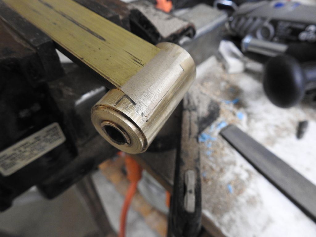
Just some shots of the prop shaft arrangement to get any suggestions before I commit.
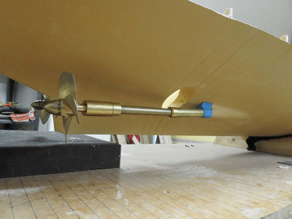
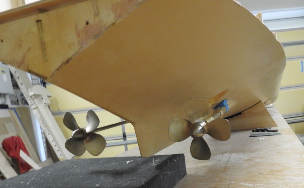
Here is an overview of the shaft from outside.
Cleaning of the planking inner surface is still not done aft and its not glassed in case I have to make any adjustments.
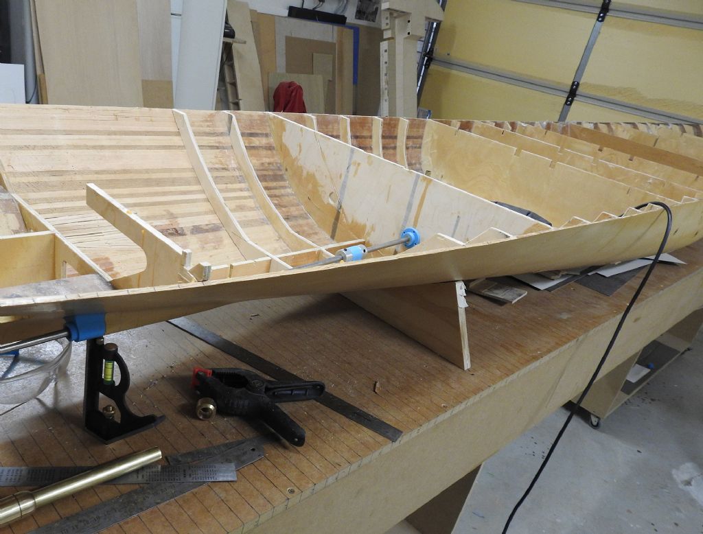
This is the thrust bearing without its stand and the gland on the motor room bulkhead
The gland is printed from ABS as are all blue parts and it has a tapered flange that matches the shaft angles, which means by rotating it I can adjust its optimal angle and lock it off with screws.
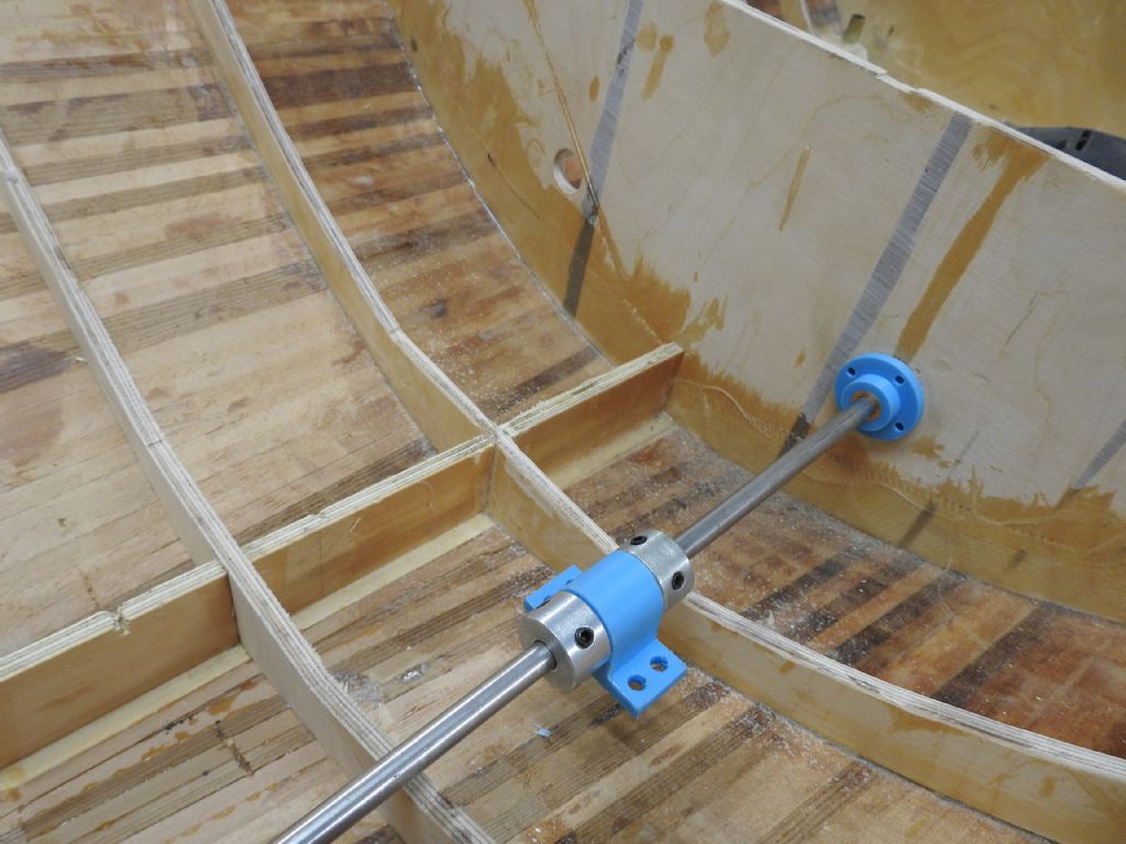
The bronze bearing inside the thrust housing.
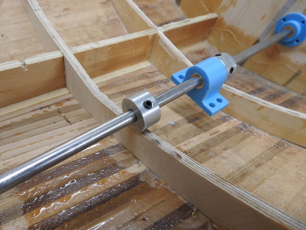
This messy shot is the inside of the boss end casting that also houses a bronze bearing, seen here.
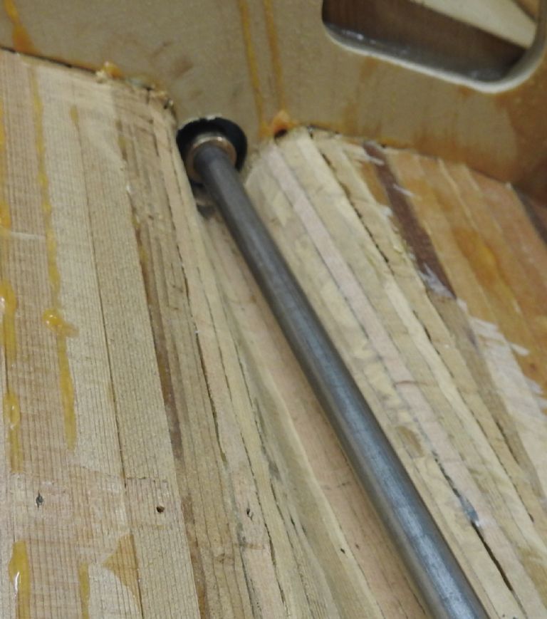
And finally the outer shaft parts that do not turn showing how it will sit over the boss end casting flange and be held against the A bracket.
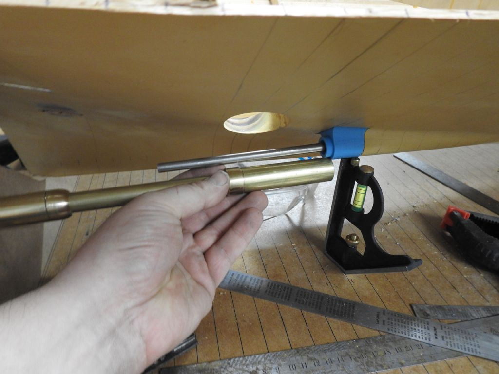
To finish off I will be making another gland with a threaded cap that compresses stuffing or O rings not sure which way to go yet…, this will be mounted aft of the thrust bearing and will be mounted on a watertight box to contain any leakage from the shaft space which can then be pumped out
Aligning shafts is a horrible job!!
Edited By Richard Dunn 3 on 14/08/2016 01:44:48
Edited By Richard Dunn 3 on 14/08/2016 01:51:55
 Ray Wood 3.

![dscn1144[1].jpg dscn1144[1].jpg](/wp-content/uploads/sites/5/images/member_albums/148754/687813.jpg)
![dscn1145[1].jpg dscn1145[1].jpg](/wp-content/uploads/sites/5/images/member_albums/148754/687812.jpg)


