Resurgam Submarine

Advert

Resurgam Submarine

Home Forums Scratch build Resurgam Submarine

  • This topic is empty.
Viewing 25 posts - 126 through 150 (of 227 total)
  • Author
    Posts
  • #51218
    Len Morris 2
    Participant
      @lenmorris2

      Hi Bob W,

      Thanks for your kind comments. I think you are the man of 'great precision'! ( I downloaded "Dashwood" and it was excellent reading). I just keep getting it wrong until it works and sometimes it does mi head in! One step forwards and three back! You'l see from my next posting.

      Len

      Advert
      #51219
      Len Morris 2
      Participant
        @lenmorris2

        Hi Everybody,

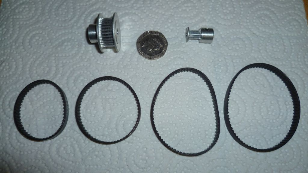
        Just an update and hopefully some useful information. When I shortened the Raboesch propshaft to suit Resurgams hull, I left some 14 mm of threaded drive shaft protruding out of the stern tube internally. Should have been enough for any conventional boat but it was wrong on two accounts. The pulleys are 17mm wide and there need to be lock nuts on either side. Also, the pulley bore is 4mm and "4mm threads" are a lot less. I'm not going to have an eccentrically running pulley so need to make a new shaft (Stubbs siver steel) and have a design think!

        Pulling the threaded shaft in and out of the stern tube so many times obviously destroyed the water tight seal. Happily I managed to find replacements for when the job is sorted.

        I'm still playing with the position of the motor so one drive belt wasn't going to do the job. I had to buy a selection to give some scope.

        My brain hurts!

        Lendrive belts and pulleys 008.jpg

        #51301
        Amy jane September
        Participant
          @amyjaneseptember49770

          It will all be so worth it when it's done……smiley

          #51499
          Len Morris 2
          Participant
            @lenmorris2

            Hi Everybody.

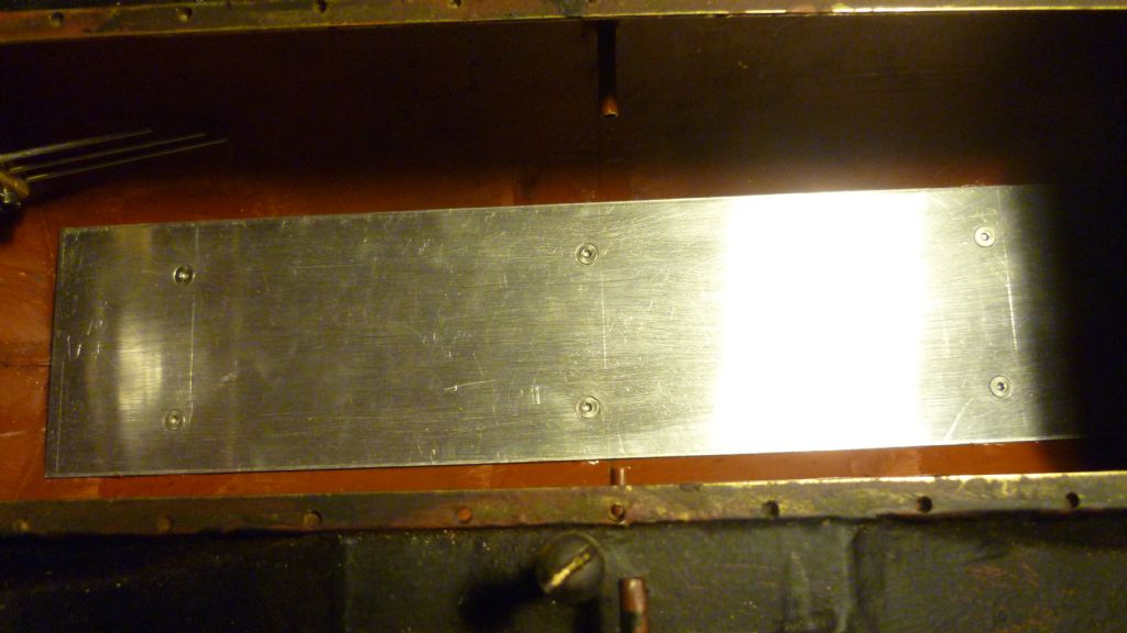
            Now have the lower deck in place. Was a bit of a problem but sorted.

            Len.deck 020.jpg

            #51504
            Bob Abell 2
            Participant
              @bobabell2

              Hello Len

              You are conspicuous by your absence!……..Says your pal…….Dave Forrest!

              He hoped you would make a appearance here at the ModeBoat Conference, Haydock

              Got a picture of his Resurgum, but it won't post on the thread from here

              Bob

              #51512
              Bob Abell 2
              Participant
                @bobabell2

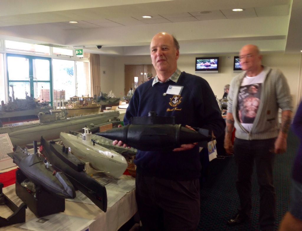
                This stand was devoted to the Submarine Age and there were plenty of weird submersibles on show

                This model of the Resurgam had a water chamber and pump unit and is said to work quite well

                Bob

                image.jpg

                #51514
                Len Morris 2
                Participant
                  @lenmorris2

                  Hi Bob A,

                  Gotcha! I was at the show with mi boat about noon on Sunday. Talked with Dave for about an hour about Resurgam and he was kind enough to take his boat apart and show me how he'd done it.

                  Basically, he has a diving drain pipe around which he can wrap a Resurgam hull, a Nordenfeldt hull or whatever. Very clever!

                  Not quite my style though as I like mi boats to be specific. Also, mi intended ballast tank system and blow system was much criticized. Too high a pressure and over complicated. Can't argue as these chaps have working subs and I don't. However, you plough your own furrow!

                  The show itself was excellent. Pig in muck!

                  I'm sure we will meet eventually!

                  Len

                  Edited By Len Morris 1 on 24/08/2014 23:52:00

                  #51762
                  Len Morris 2
                  Participant
                    @lenmorris2

                    engine 036.jpgengine 010.jpgengine 009.jpgHi Everybody

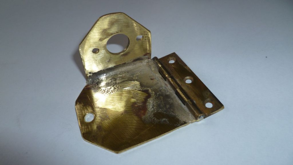
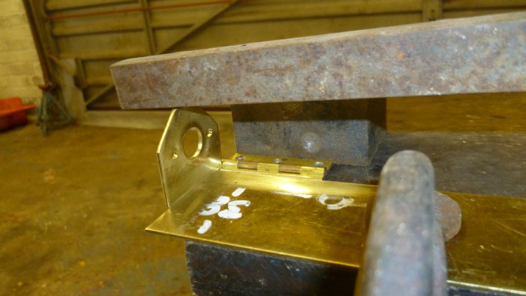
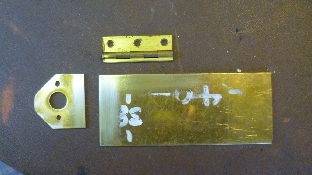
                    Now have the motor installed and a propeller that propellers! Here are pics of the motor mount silvered soldered out of brass.engine 001.jpg

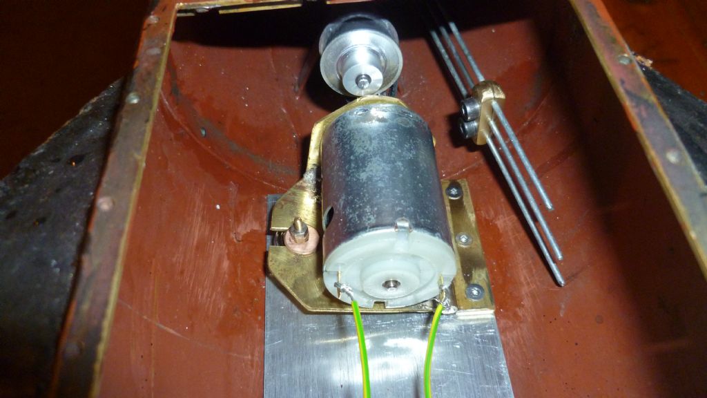
                    Then here's a picture of the engine installed in the hull:-engine2 001.jpg

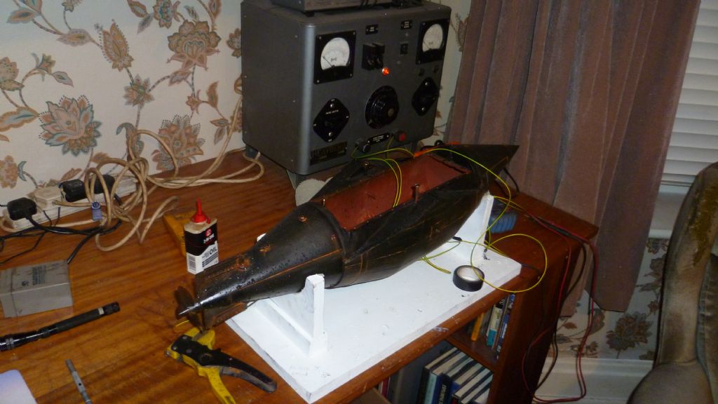
                    And finally a picture of mi test rig and actual engine testing:-engine 039.jpg

                    Know the pics are all out of order with the text but just can't work out the logic of this site to get everything in the right sequence.

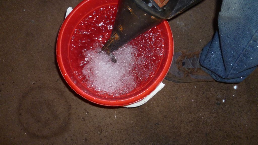
                    Anyway, the motor is now installed! The pic above shows my bench power supply which indicates volts and amps. At the first set up the motor was dragging 5 amps at almost 6 volts and no speed in fresh air! I had far too much tension on the belt drive and a slight axial alignment error. Have learnt something about tooth belt drives. You must get them them in line to stop friction on the side of the belt and a lot of belt tension isn't needed,let the teeth do the work. There's a trick to lining them up but I'll go into that later. Big doos and little doos ended up dragging 2.5 Amps at 6 volts with the prop in a bucket of water splashing it everywhere. Very happy!

                    In MB Feb 2010 Glynn Guest wrote an excellent article 'Meter Modelling'. Well worth a read. Monitor your amps and adjust you motor alignment for the lowest reading. Works a treat!

                    Now the motor is in, need to get the solenoid in for the rudders.

                    Len

                    #51765
                    Bob Abell 2
                    Participant
                      @bobabell2

                      Len

                      Don`t tell me you`ve butt jointed the motor mount and hinge to the base plate?

                      I realise you`ve silver soldered the joints, but you could have used nuts and bolts!…..lol

                      Can`t make out your first picture?

                      My pc can`t get the picture posting in the right order!

                      Can`t add text after the photo`s either

                      There`s something wrong with the system, somewhere

                      Bob

                      #51783
                      Len Morris 2
                      Participant
                        @lenmorris2

                        Hi Bob A,

                        There are 3 reasons why I modified the hinge and butt jointed it. I wanted (and needed) the mount to sit flush on a flat surface. Nuts and bolts would have given no end of interference problems. Next, taking the 'Rickover' stance that if it can go wrong it will in a submarine, I eliminated 3 nut and bolts that would require a major strip down to get to – my silver solder won't come loose. And finally, when it's all tarted up it'll look right as opposed to a hinge nicked from a kitchen cabinet, which actually it is, the middle one from a set of three!

                        In reality the whole thing could have been soft soldered and still have been amply strong enough. Just another Rickover moment I suppose! The real trick in the whole affair was soldering it up and not soldering the hinge solid!

                        My first picture should have been my last picture and was the last thing I entered into the post! Why it chucked it up first thing before any text I have no idea, and it was meant to be the best bit of the post! It shows Resurgams stern stuck in a bucket of water with the motor a full thrash. Amps and Volts on the money with spray everywhere (you did ask Bob when you could expect to see her in the water)! The pics in my album if it's a definition thind.

                        I've found that after posting a picture, if you put the cursor at the extreme bottom right and hit return it will put you back into text mode. That's just my PC and it could be different for others. The logic I am now trying is first write the text, then add the pictures in reverse order!

                        I agree, 'There's something wrong with our bxxxxx ships today'!

                        Best regards,

                        Len

                        #51795
                        Bob Abell 2
                        Participant
                          @bobabell2

                          Gotcha, Len

                          I`m slightly relieved that you are having the same pc trouble with this website

                          It hasn`t always been like this

                          We need to have a word with Colin about it

                          Colin

                          "We can`t add text after a photo is loaded onto the thread"

                          Bob and Len

                          #51796
                          lnvisibleman
                          Participant
                            @lnvisibleman

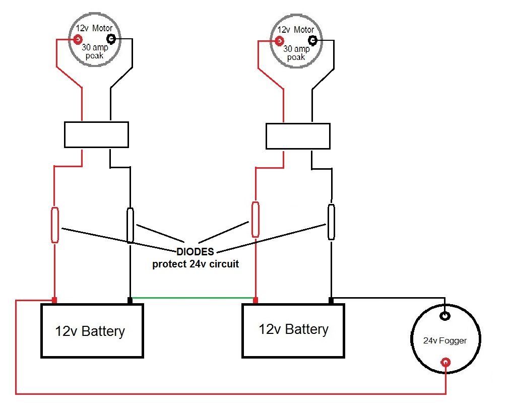
                            12v + 24v.jpgI don't seem to have too much of a problem but it is a bit fiddly. The site always wants to put the photo at the bottom of the last piece of text and then when you then type, it goes above the photo if left to it's own devices. I find that I have to tab down and across to get text in the right place.

                            Mike

                            Edited By lnvisibleman on 02/09/2014 10:48:07

                            Edited By lnvisibleman on 02/09/2014 10:48:51

                            #51801
                            Len Morris 2
                            Participant
                              @lenmorris2

                              Dear Bob A and Mike,

                              Thanks for the comments. If you read the thread 'Irrelevant Question' in the Soapbox section it covers or at least describes our concerns ( it's your thread Bob)! I suggested a thread for 'Site Solutions', but Ashley disagreed (in quite a humorous manner) and I let he matter go. Now I'm going to do it for two reasons. Firstly it needs to be done. And secondly my Resurgam thread is about Resurgam not site problems!

                              Look out for 'Site Posting – Problems and Solutions'

                              If we can focus all the knowledge of users into one thread it will be a very useful tool. I expect lots of input from Ashley!

                              Len.

                              #51881
                              Len Morris 2
                              Participant
                                @lenmorris2

                                rudder servo 001.jpgrudder servo 004.jpgHi Everybody,

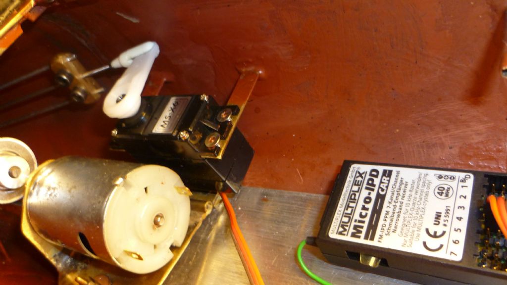
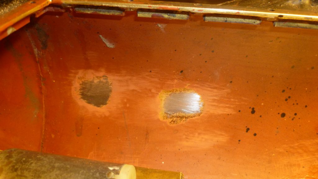
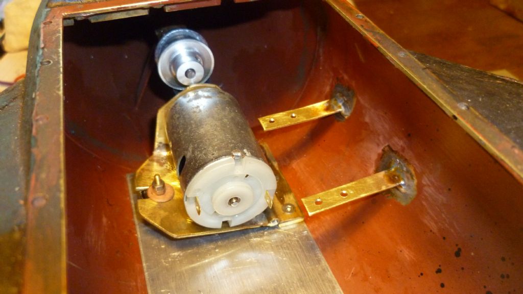
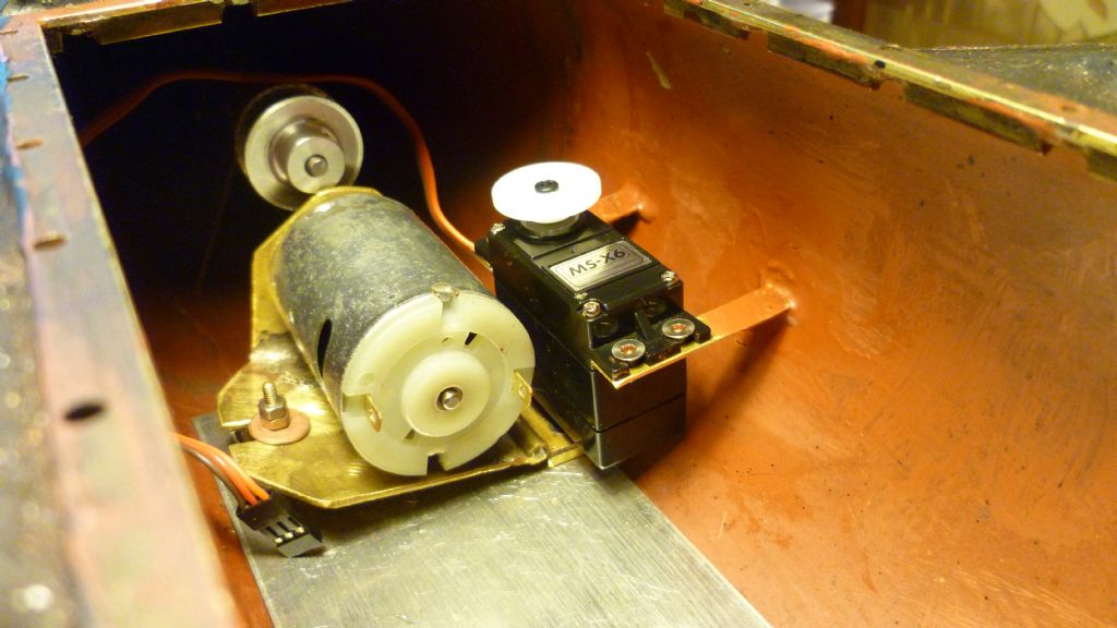
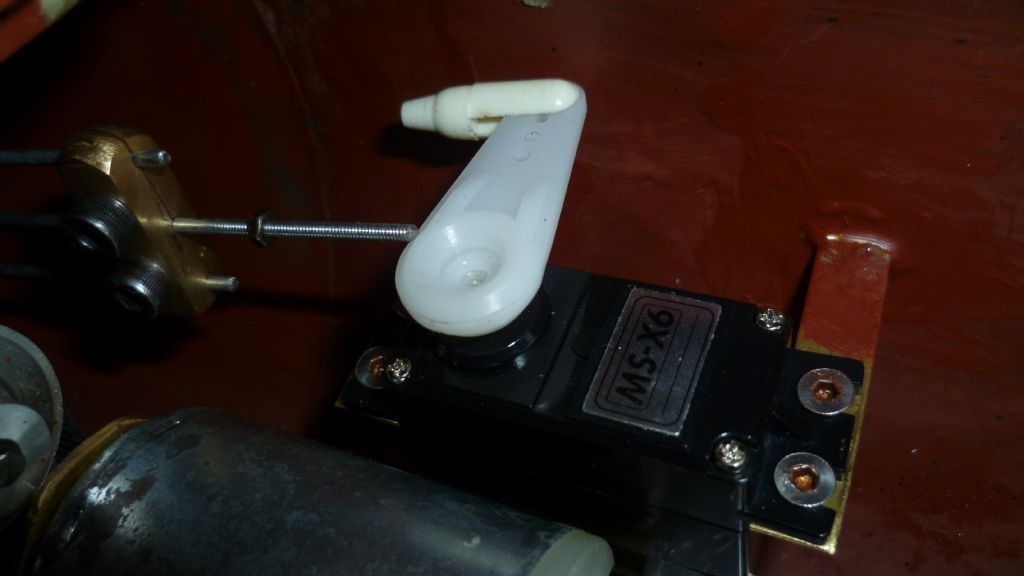
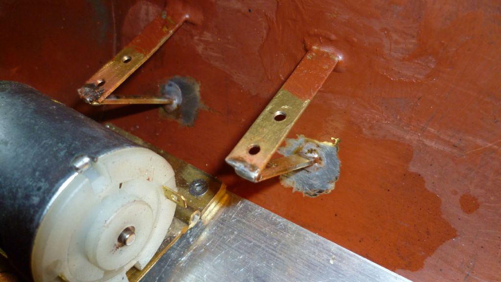
                                Now have rudder servo in place. The pictures show the hull cleaned inside (careful use of paint stripper), the brackets soldered in place and the servo mounted.

                                The exact position took a bit of thought so that everything (so far) can go in and come out. Getting the rudder control rods in is going to be fiddly and I can see some special 'Resurgam tools' having to be made. Bit like putting a ship in a bottle! Will post next when the rudders waggle.

                                Lenrudder servo 007.jpg

                                #51907
                                Amy jane September
                                Participant
                                  @amyjaneseptember49770

                                  Progressing nicely Len, and a pleasure to watch. (So very different from my "non engineering"!)

                                  #51920
                                  Len Morris 2
                                  Participant
                                    @lenmorris2

                                    Hi Everybody,

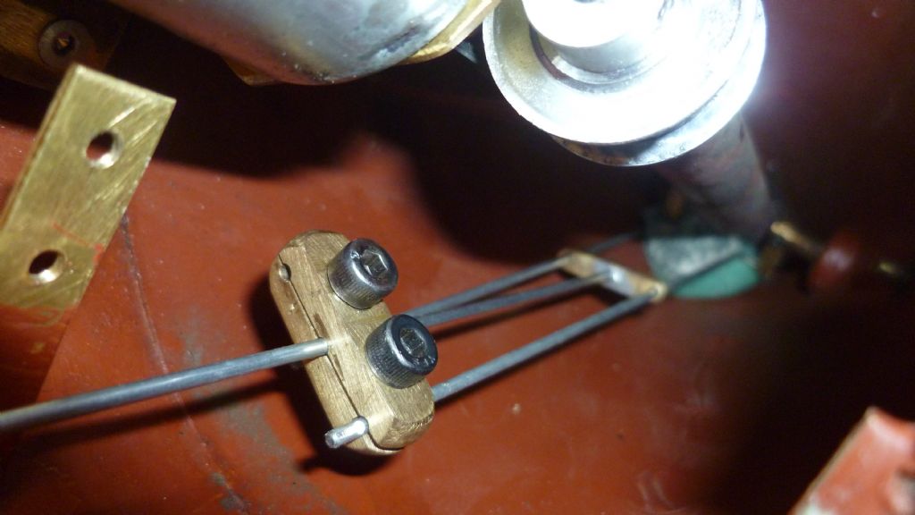
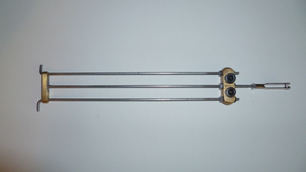
                                    We now have rudders that waggle! It was a bit of a job and took some working out. Pic one is just a recap of the control rods to be installed.
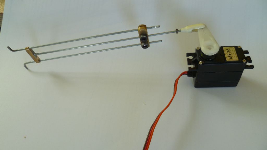
                                    rudder control rods 003.jpg

                                    Each rudder shaft is kept in place by the central keeper rod. The clamp keeps everything rigid once it's all in place. It became obvious very quickly that the only way it was going to get installed was with the hull vertical and lots of light to see what was going on. The next pic shows mi boat rubber banded to the stand and the whole thing vertical, stern down.
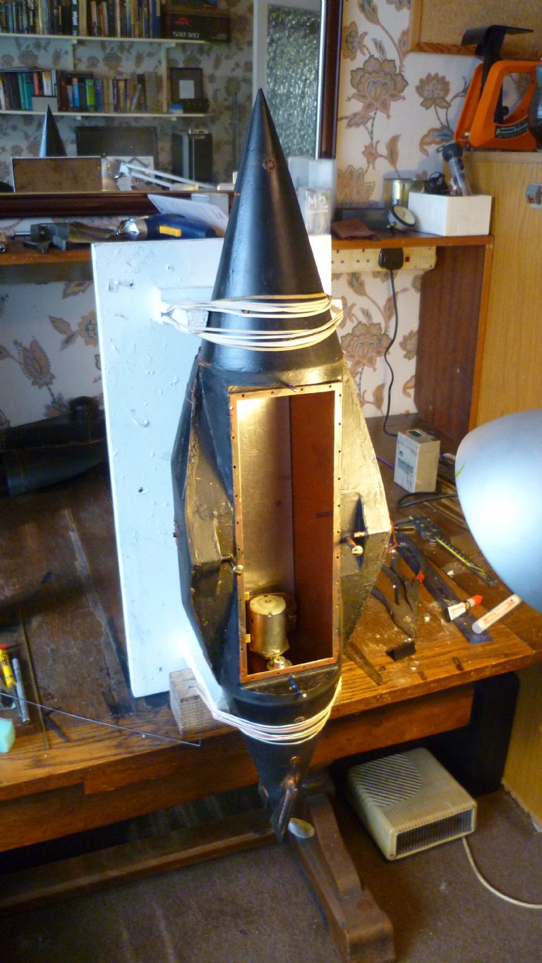
                                    rudder control rods 016.jpg

                                    Each rudder arm control rod was poked down to the stern and hooked in place. This proved quite difficult when they were cut to their correct shorter length and needle nose pliers didn't really help. The answer was to slide a bit of 2 mm bore brass tubing over the rod to extend its length for easy handling. The tube was ever so slightly bent so that it gripped the rod but could be easily slid off after the rod was in place. The rods had to be kept in place while the central keeper rod was slid into position and eventually this was done with a bit of foam rubber.
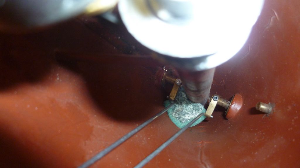
                                    rudder control rods 007.jpg

                                    This allowed to rods to be moved about while the keeper was slid on.
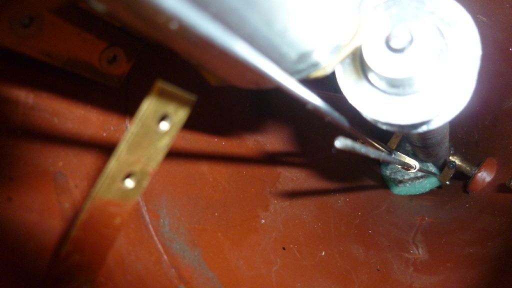
                                    rudder control rods 008.jpg

                                    Next the clamp was slid on………..

                                    rudder control rods 011.jpg

                                    …….and the whole assembly aligned and tightened. Here's everything in place.
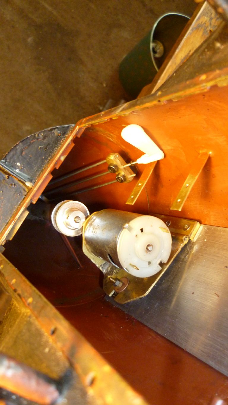
                                    rudder control rods 012.jpg

                                    And Finally the waggle test.

                                    rudder control rods 017.jpg

                                    It works, we have rudders! Rock solid and no play. Whew, Job Done!

                                    Just to close thought I'd just chuck in some of my thoughts about Resurgams rudders. I don't think Garrett excelled himself in this area. They are completely unbalanced. Worse, the centre of pressure must be around the extreme tip of the blades. To mechanically get hold of the blades it's done at the thinnest point and they are in front of the propeller.
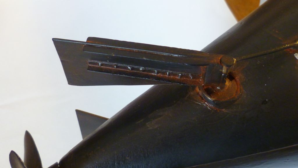
                                    rudder design 003.jpg

                                    It will be interesting to see how they perform but I've resigned myself to living with a lot of rudder damage.

                                    Len

                                    #51970
                                    Len Morris 2
                                    Participant
                                      @lenmorris2

                                      Hi Everybody,

                                      Just an update. While trying to set up the R/C and rudder linkage, managed to pull the plastic clevis straight of the end of the control rod.

                                      001.jpg

                                      Not surprised to be honest. To get the job underway the clevis was stolen from my HMS Daring destroyer. Old plastic and probably threaded 8BA. Seemed OK and tight enough at the time but made mental note that an upgrade would be required. Resurgams rudders are heavy due to the O ring seals. The clevis lasted about 20 waggles! Metal ones ordered and received today.

                                      002.jpg

                                      Unfortunately they would not screw cleanly on to the control rod and became very tight before the rod could exit the bore of the clevis. Time for some validation. An M2 tap flew down the bore of the clevis with no problem at all. My new M2 die flew down the control rod (and it's not a split die) so should give the correct diameter. A commercial nut flies down the control rod and a commercial M2 bolt screws easily into the clevis.

                                      003.jpg

                                      The only conclusion is that the thread on the rod is skewed because it was done by hand. Short female threads don't have a problem but the long ones in the clevis do.

                                      Time for a remake. The central control rod is going to get re-threaded in the lathe using the tail stock die holder. This will fix the immediate problem. However, while all the kit is out the individual rudder control rods are going to get threaded also so they can be nutted either side of the clamp.

                                      006.jpg

                                      This is just another 'Rickover ' moment to ensure there can be no slippage. As a final note, there was some flex on the servo mounts. Nothing significant but unexpected. They are going to be braced back to the hull for rigidity.

                                      Len
                                      #52113
                                      Len Morris 2
                                      Participant
                                        @lenmorris2

                                        Hi Everybody,

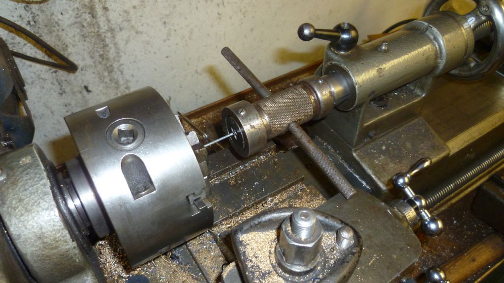
                                        The thread on the control rod was corrected in the lathe. Should have done it in the lathe the first time round but small threads are deceptive and you can get away with it until some accuracy is needed. The good thing is that M2 thread is so fine, you can thread at normal low speed and not have to mess about in back gear.fixing rudder 004.jpg

                                        Here's a picture of the final rudder control assembly once all the rods were threaded.

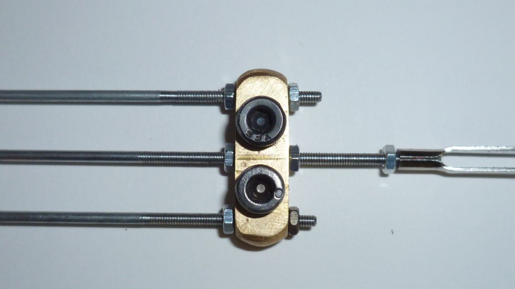
                                        fixing rudder 009.jpg

                                        And here is a close up of the nutted assembly. The nuts don't have to be particularly tight. They just guarantee there can be no slippage at the clamp arm.

                                        fixing rudder 011.jpg

                                        The servo mounts were braced which obviously increased their rigidity enormously.

                                        fixing rudder 012.jpg

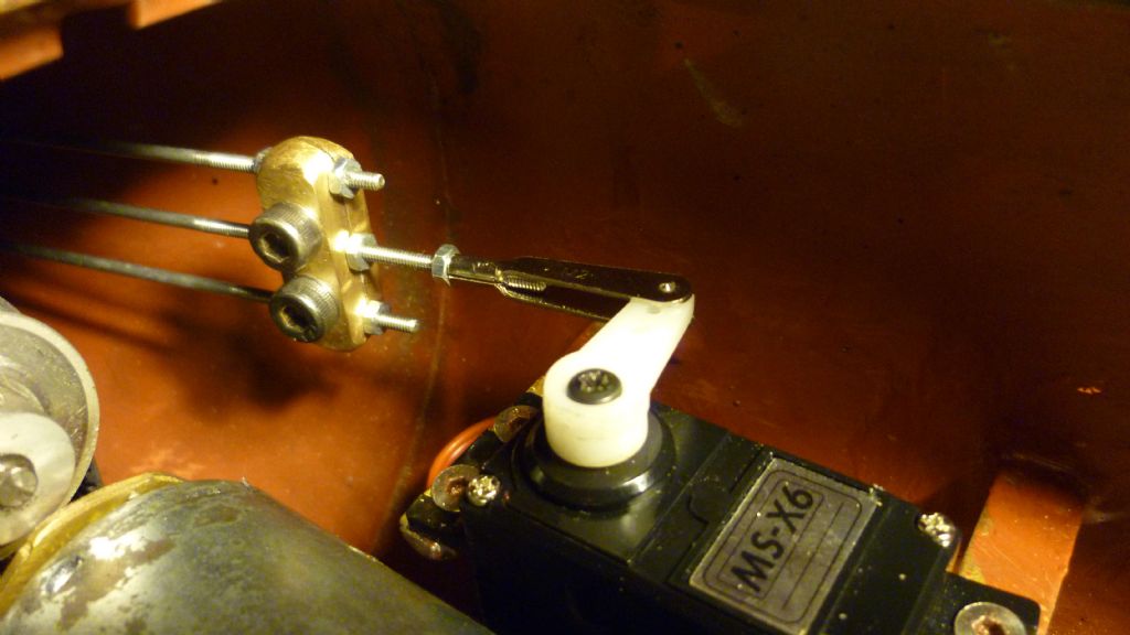
                                        Then after a bit of a paint everything was reinstalled. Much less of an effort this time as I made some specific Resurgam tools. Here's a picture of the final job.

                                        fixing rudder 021.jpg

                                        The servo arm has been shortened to get the geometry right. Rudder done. End Of.!

                                        Next job is the main battery installation and this needs to be slideable fore and aft under servo control to maintrain level trim. I have a cunning plan!

                                        Len
                                        #52170
                                        Amy jane September
                                        Participant
                                          @amyjaneseptember49770

                                          ……a plan so cunning you could pin a tail on it , and call it a weasel?

                                          Keep up the good work!

                                          #52444
                                          Len Morris 2
                                          Participant
                                            @lenmorris2

                                            More cunning than a fox that's just been appointed Professor of cunning at Oxford University!
                                            #52466
                                            Amy jane September
                                            Participant
                                              @amyjaneseptember49770

                                              Now that is cunning

                                              I shall look forward to the revelation!

                                              #52513
                                              Len Morris 2
                                              Participant
                                                @lenmorris2

                                                Hi Everybody,

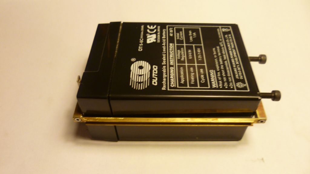
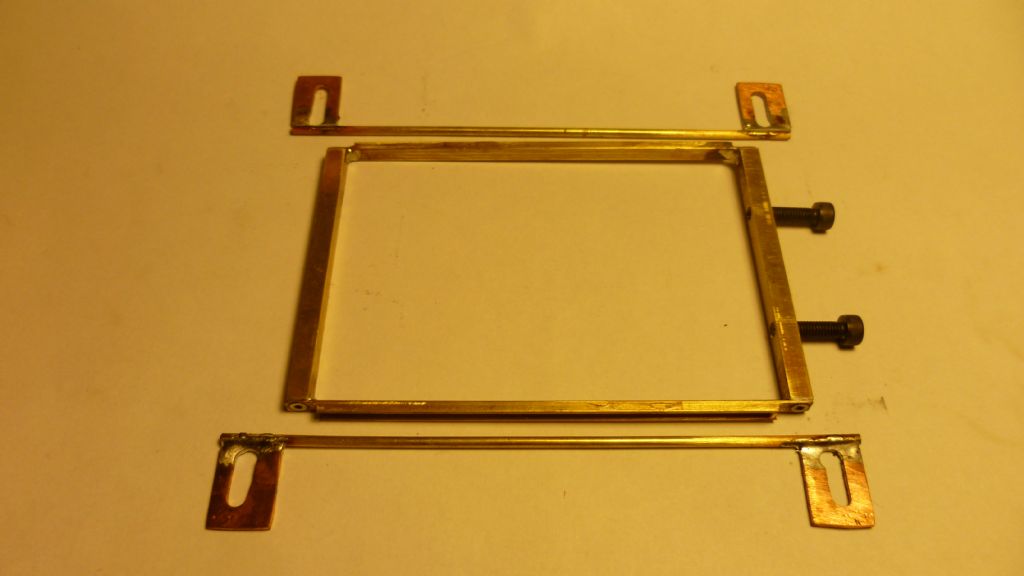
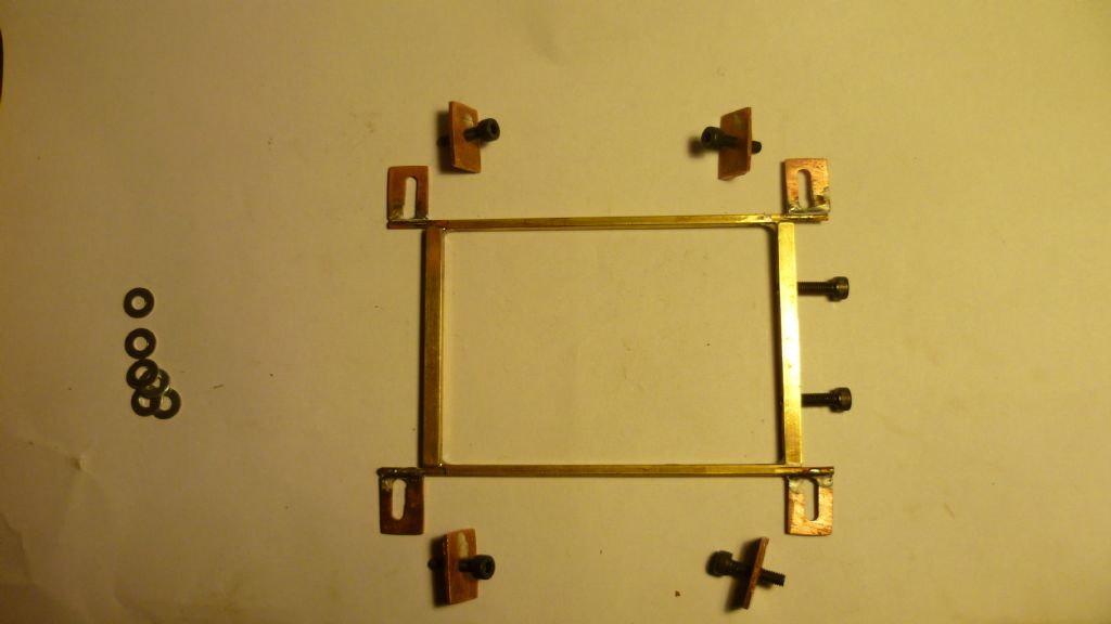
                                                Here's how I've installed the battery. Job one was to get hold of it. Although they look nice and square and brick shaped they're not. They have a fine taper top to bottom of about 2mm on all sides. So, made a brass frame that is true, to clamp around the battery casing. It's soldered and screwed so it ain't cumming apart.

                                                bat mount 005.jpg

                                                The fore and aft side pieces are brass channel sections. These slip onto guide rails that are soldered to the hull.

                                                bat mount 016.jpg

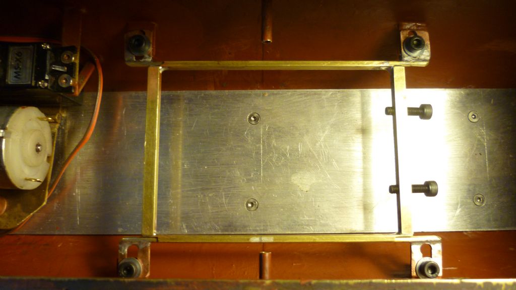
                                                The next pic shows the rods in the frame with the lugs that were soldered to the boat.

                                                bat mount 023.jpg

                                                Here it is soldered in the hull.

                                                bat mount 036.jpg

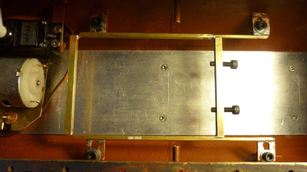
                                                And here is the frame slid full astern.

                                                bat mount 032.jpg

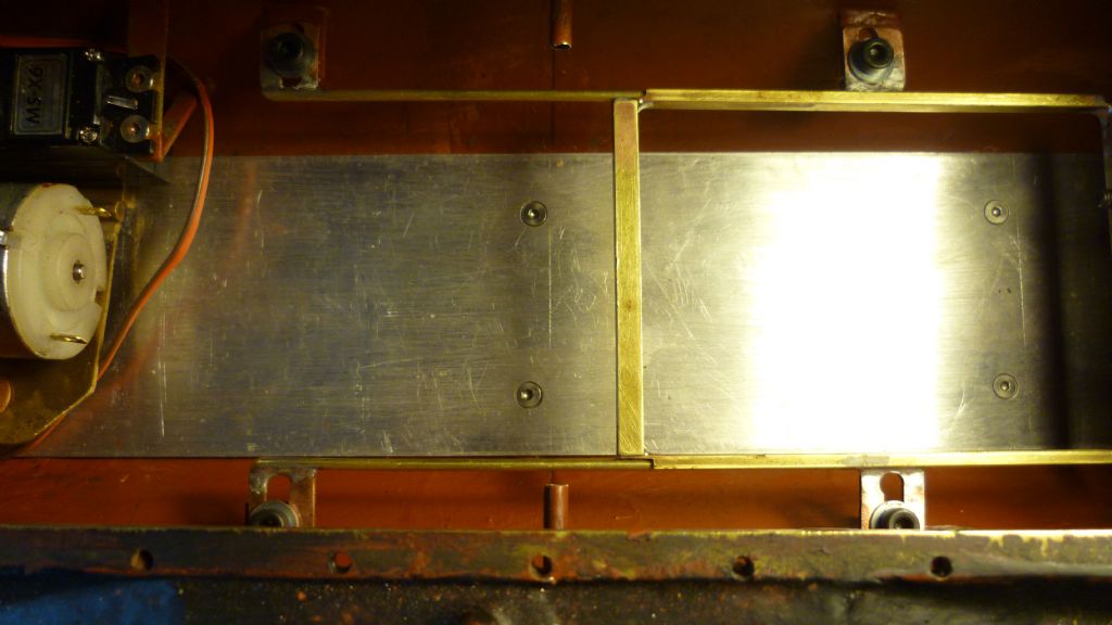
                                                And full forwards.

                                                bat mount 033.jpg

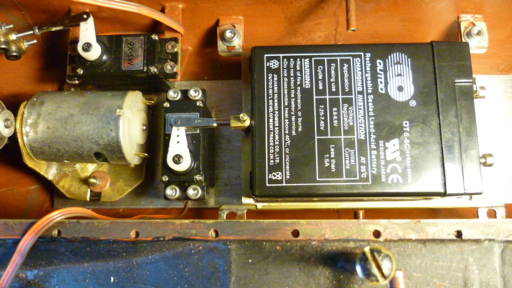
                                                There is no way such extreme movements will be required but it just shows the potential. The final pic shows the battery in place and the servo position. Yet to be installed but that's an easy matter. Very happy with the result. Everything is adjustable and once everything is locked in place, the battery slides like the top slide on a lathe.

                                                bat mount 040.jpg

                                                Not very happy with the slotting on the brass strips but that's another story! Job done. Now for the hydroplanes.

                                                Len

                                                #52550
                                                Len Morris 2
                                                Participant
                                                  @lenmorris2

                                                  Hi Everybody,

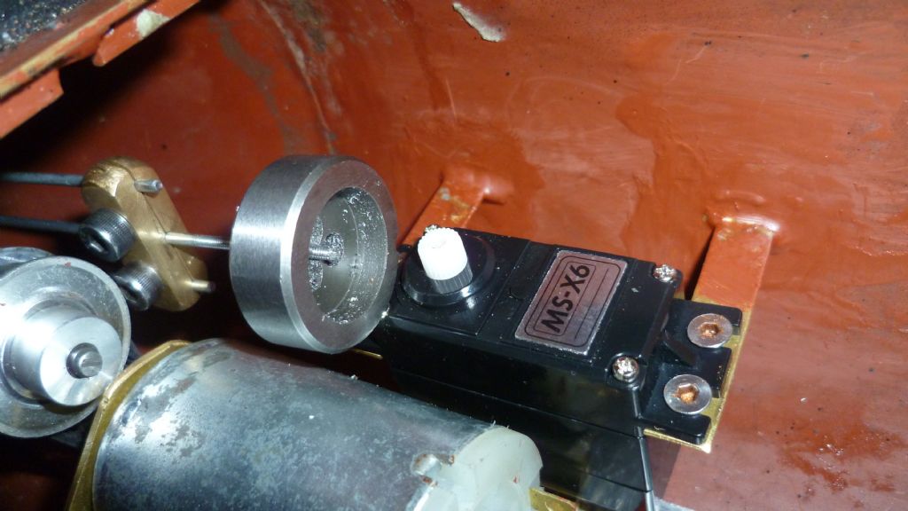
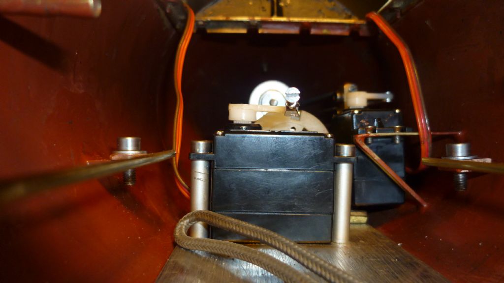
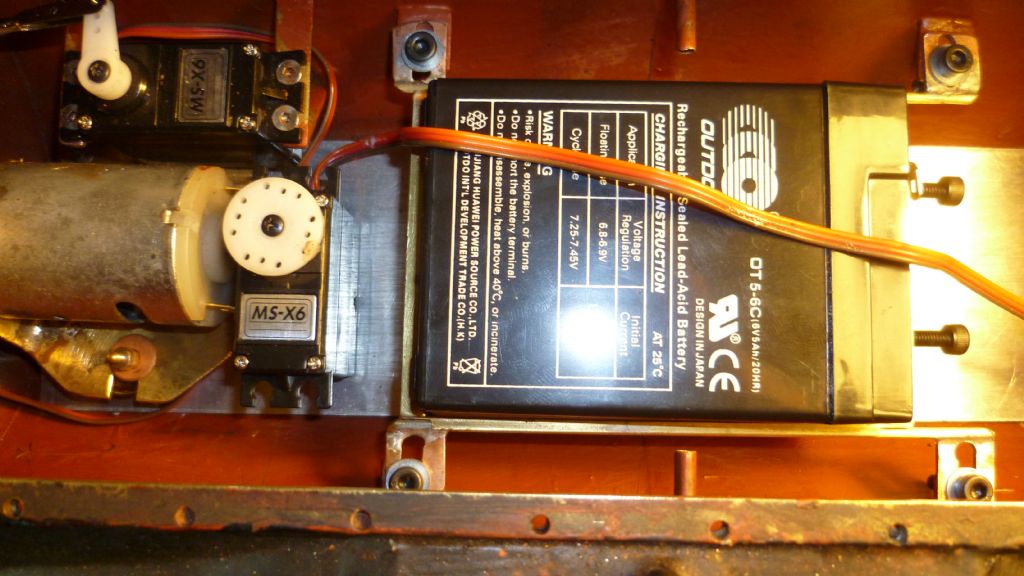
                                                  Just a couple of pics to show the finished battery installation. The servo was screwed to the deck plate on 4 aluminium pillars:-

                                                  004.jpg

                                                  There was no room for a control rod as such. It ended up being an 'eye' screwed directly onto the clevis and working on a vertical pin soldered into the battery frame. The eye was reamered to make sure there was no play at the pin joint and the fastenings were replaced with stainless steel.

                                                  sliding frame 002.jpg

                                                  The battery can be slid 10 mm either side of it's centre of gravity which is set directly under the hydroplane shaft. This gives a weight shift of some 300 grams (150 on the bow and 150 off the stern and vica versa). I'm hoping this will be enough to control the pitch fast enough for what will be a 7 kg boat at neutral buoyancy.

                                                  We'll see!

                                                  Len

                                                  #52593
                                                  Len Morris 2
                                                  Participant
                                                    @lenmorris2

                                                    Hi Everybody,

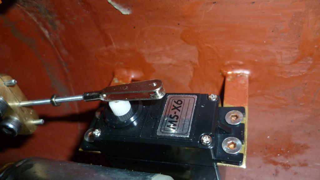
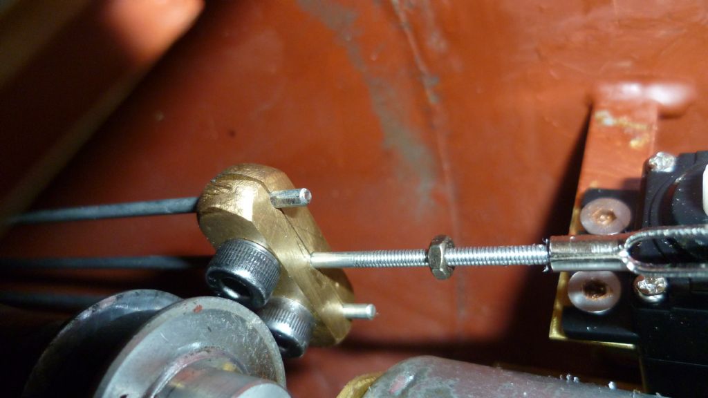
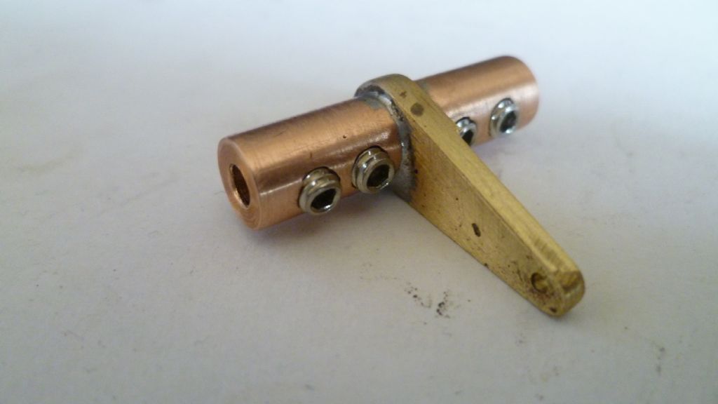
                                                    Just an update. Here's the fitting I made to connect the hydroplane shafts:-

                                                    hydroplanes 001.jpg

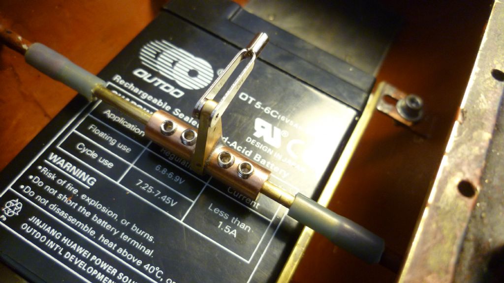
                                                    ….and here it is installed:-

                                                    hydroplanes 008.jpg

                                                    Notice the silicon tubing where the shafts enter the hull. They are quite tight and do an excellent sealing job. The planes only have to move say 30 degrees in each direction and the silicon copes with the job easily, without slipping on the tube or shaft and without putting any undue load on the system.

                                                    Now need to install the hydroplane servo.

                                                    Len

                                                    #52626
                                                    Amy jane September
                                                    Participant
                                                      @amyjaneseptember49770

                                                      Looking good Len.

                                                      I had imagined something similar for moving the battery fore and aft, but had envisioned a long screw to shift the tray back and forth, expecting more movement. Are you going to couple the hydroplanes and weight shift or operate independently?

                                                      Aj

                                                    Viewing 25 posts - 126 through 150 (of 227 total)
                                                    • Please log in to reply to this topic. Registering is free and easy using the links on the menu at the top of this page.

                                                    Code of conduct | Forum Help/FAQs

                                                    Advert

                                                    Latest Replies

                                                    Home Forums Scratch build Topics

                                                    Viewing 25 topics - 1 through 25 (of 25 total)
                                                    Viewing 25 topics - 1 through 25 (of 25 total)

                                                    View full reply list.

                                                    Advert

                                                    Newsletter Sign-up