TEV Wahine 1/35 Build

Advert

TEV Wahine 1/35 Build

Home Forums Scratch build TEV Wahine 1/35 Build

Viewing 25 posts - 201 through 225 (of 411 total)
  • Author
    Posts
  • #67231
    Banjoman
    Participant
      @banjoman

      I should have said, too, that to the extent that such things can be judged from photos and descriptions, or from my admittedly very limited experience, I'd say your thinking about the feasibility of soldering both struts at the same time with the new, milled set-up is spot on.

      Again, this is truly impressive work!

      Mattias

      Advert
      #67232
      Richard H Dunn
      Participant
        @richardhdunn

        Thanks Mattias

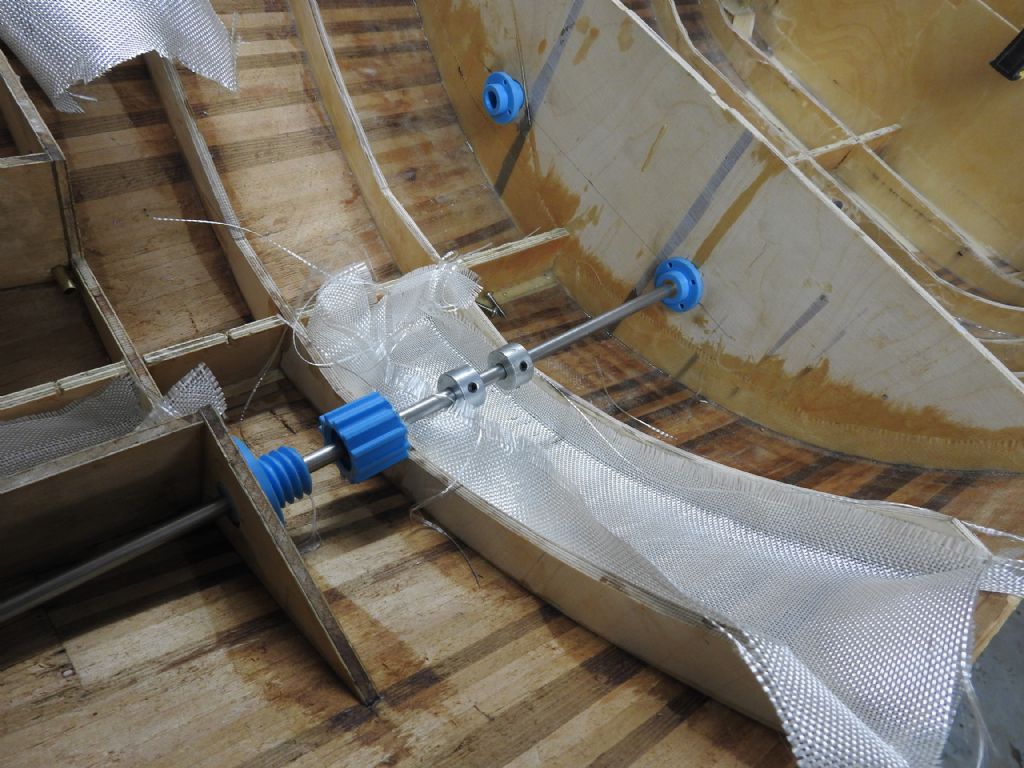
        Here are some shots that show the workings of the shafts.

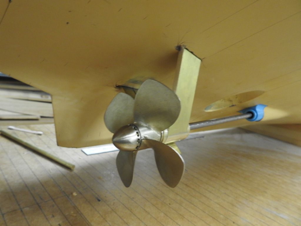
        Below is the A bracket being aligned (minus outer shaft covers) and having the prop checked in 3 axis , once done I will mark of struts where it meets shell of hull and cut to shape and then solder to boss.

        bracket to trim.jpg

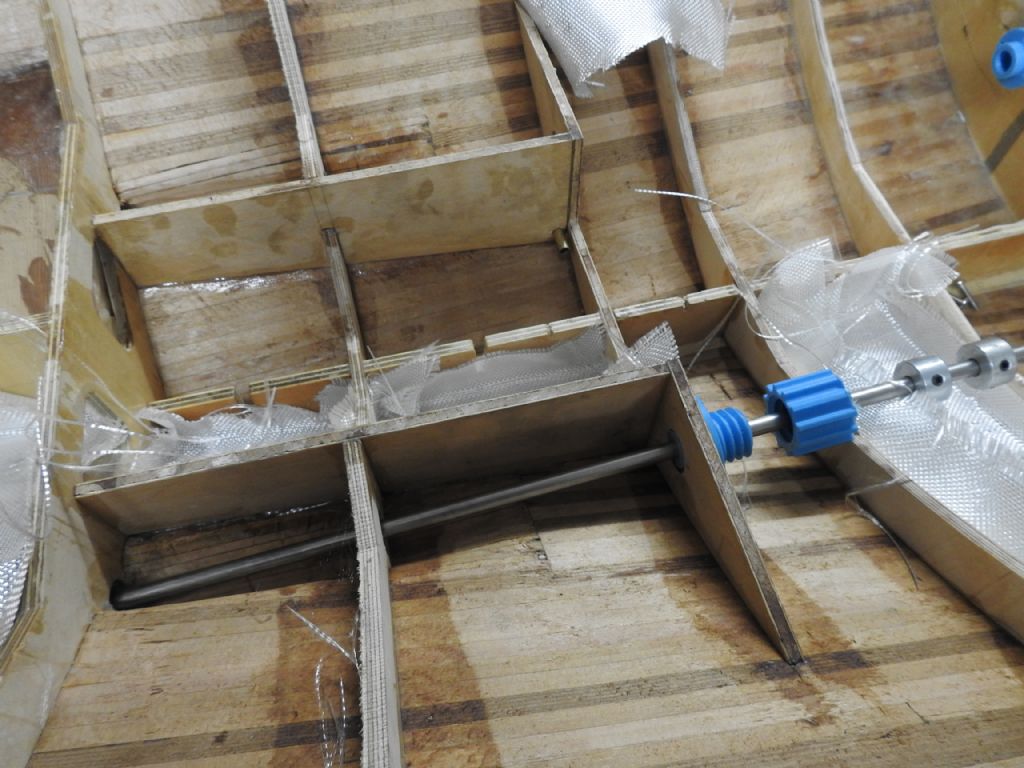
        This shot shows the Shaft sump that collects the expected leakage and the pump outlet can be seen in the lowest corner.

        It will have a screwed down water proof lid.

        shaft sump.jpg

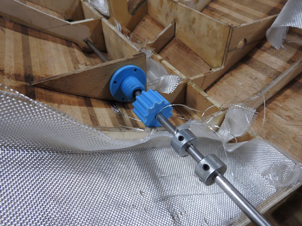
        The below photo shows the blue stuffing box in position and the 2 O rings sitting in the recess,the idea is the cap will screw down and very slightly compress the rings which are a little proud and create a watertight seal around the shaft, it should work in theory.

        The collars are for the thrust bearing which is not in this shot.

        o rings .jpg

        shaft overview.jpg

        #67233
        Richard H Dunn
        Participant
          @richardhdunn

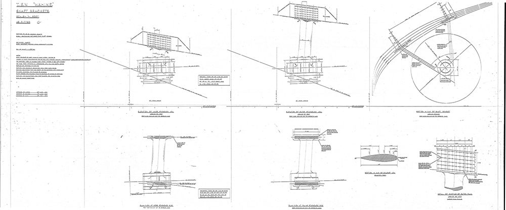
          For those who like plans

          Here are the plans for the Shaft Bracket, It's so much easier to do things when you have plans and guesswork is not required.

          shaft brackets plan.jpg

          #67248
          Richard H Dunn
          Participant
            @richardhdunn

            I had success with brazing the A bracket and it is now bolted in place ready for final shaping, packing and glassing in.

            I have to tell you my heart was in my mouth the whole time.


            I had to put holes in the hull to drill for bolts but will repair before glassing

            dscn1159[1].jpg

            dscn1160[1].jpg

            vlcsnap-2012-05-09-07h40m49s130.jpg

            dscn1162[1].jpg

            dscn1163[1].jpg

            Edited By Richard Dunn 3 on 22/08/2016 07:11:48

            Edited By Richard Dunn 3 on 22/08/2016 07:13:34

            #67290
            Richard H Dunn
            Participant
              @richardhdunn

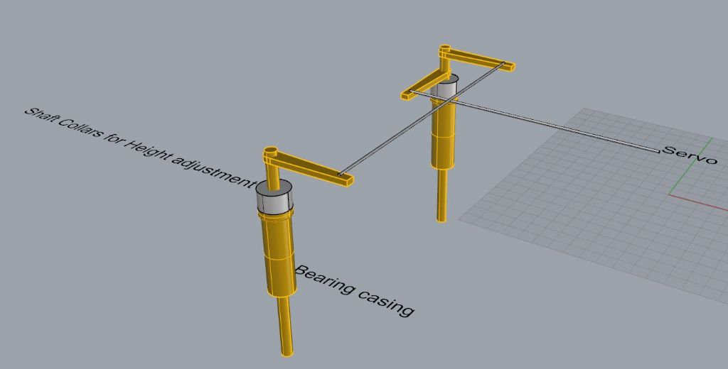
              Any body have any comments about the rudder linkage system they would care to share.

              The Bearing casing houses a 20mm long bronze bearing, and the 8mm shaft has a collar on it to lock the height.

              rudders.jpg

              #67293
              Dave Milbourn
              Participant
                @davemilbourn48782

                Richard

                I would recommend using ball-and-cup connectors between the rods and the tiller arms to eliminate any slop in the linkage. I believe there are heavy-duty ones available which are used in large-scale RC model off-road vehicles. I'll maybe go Googling for these later while I wait for some resin castings to set. What do you propose to use for the rods e.g. diameter and material?

                Dave M

                #67296
                Colin Bishop
                Moderator
                  @colinbishop34627

                  Looks like a conventional setup Richard. I assume that there is a bearing on the rudder stocks above the blades to prevent them riding up.

                  Although probably unnecessary for someone with your skills, you might want to consider introducing adjusters in the cross rod and particularly the rod leading back to the servo to allow fine tuning when setting it all up.

                  And of course you need to have access to the whole setup in the future should the rudders need to come out for any reason!

                  I'm probably telling Grandma how to suck eggs here!

                  Colin

                  #67297
                  Dave Milbourn
                  Participant
                    @davemilbourn48782

                    Here's some examples of what I mean **LINK**

                    Threaded rods will permit fine adjustment, as Colin suggests.

                    DM

                    #67298
                    Colin Bishop
                    Moderator
                      @colinbishop34627

                      That's a useful link Dave. Very handy if you need proper engineering although my models are usually small enough that the innards of chocolate block connectors provide an adequate adjustment facility…

                      Colin

                      #67299
                      Richard H Dunn
                      Participant
                        @richardhdunn

                        Thanks guys

                        Yes there is a bearing on the lower end of the horn and as far as what I am using for linkages I really have no idea, I need to decide though as I need to bore the tiller arm with holes to accept whatever I choose before I put the rudder shaft in.

                        The rudder bolts on just like the proper one.

                        Actually I will show you the plan

                        #67300
                        Richard H Dunn
                        Participant
                          @richardhdunn

                          Sorry Its the worst plan by far this one as its so old the linen slips in the scanner and the plan was 3m long, but hopefully you can see the design and how it has a lower bearing and how it bolts on.

                          rudder.jpg

                          #67312
                          Richard H Dunn
                          Participant
                            @richardhdunn

                            Thanks for that Dave, much appreciated indeed.

                            I'm onto it trying to find one that has the span between rudders of 225mm!.

                            Another thing guys I see people using a piano wire linkage to the servo with a v bend in it to remove slop? any thoughts or do you think given my scale I should use these ball joints for that as well?

                            Edited By Richard Dunn 3 on 24/08/2016 22:44:06

                            #67314
                            Colin Bishop
                            Moderator
                              @colinbishop34627

                              I don't like piano wire personally, I prefer to use thin section brass tubing which is very rigid. I incorporate a degree of adjustment as even if you get the geometry correct, the servo mid point position can be a degree or two out. You can increase the rigidity if necessary by sleeving another length of brass tubing over the central part of the connection.

                              Colin

                              Edited By Colin Bishop, Website Editor on 24/08/2016 22:56:11

                              #67315
                              Dave Milbourn
                              Participant
                                @davemilbourn48782

                                Richard

                                I think the V bend is to prevent the force of any sudden impact to the rudder from damaging the output gears of the servo. There are commercial items called Servo Savers which do the same thing, albeit at a price… I can't recall seeing any model boat equipped with anything like these; they are usually fitted to the steering servo of model cars and the nosewheels of model aircraft. That said, I've never seen a model boat the size of yours!
                                I would suggest using plain steel pushrods of 3mm diameter with a thread cut on each end to fit the ball-joints. Keep the rods as short as you possibly can. If you want details of a servo-saving mechanism then just shout – I could conjure up a drawing for one in fairly short order.

                                Dave M

                                #67317
                                Colin Bishop
                                Moderator
                                  @colinbishop34627

                                  I rather doubt if Richard will run this model aground so a nice tight linkage setup should be the objective. If the worse happens then servos are cheap to replace. My opinion only of course!

                                  Colin

                                  #67320
                                  Richard H Dunn
                                  Participant
                                    @richardhdunn

                                    Done some research since last post seems getting tie rod arms that long will be impossible so will have to make them myself, guess I can braze a nut on the shaft for winding adjustment

                                    #67321
                                    Richard H Dunn
                                    Participant
                                      @richardhdunn

                                      All done, I have ordered a 16 pack of traxxas 3mm end joints,

                                      Thanks guys

                                      #67323
                                      John W E
                                      Participant
                                        @johnwe

                                        Hi there

                                        Personally I prefer the closed loop system of rudder linkage. This is where you have 2 push rods from the servo going to the arms of the rudders and the rudders are connected with a tie bar – all adjustable. The reason for this is it evens out the stress on the servo. Think of a man riding a bike using one hand and one arm to steer on the handle bars. Its a lot easier if you have 2 hands on the handle bars to turn the corner.

                                        I have including a pic of one of my models – admittedly this is a 3 rudder model – but the system is still the same.

                                        invisible john43 servo and rudder linkages (medium).jpg

                                        #67345
                                        Richard H Dunn
                                        Participant
                                          @richardhdunn

                                          Thanks Bluebird.

                                          I do see the advantage of what you are saying but it seems to me that it would work better for single or triple blade rudders, but for double you would have to fit a central dummy post with no slop to drive the 2 outer ones for this to work to advantage, which is like the way it was done on the original.

                                          But will look into it and do some tests. I should be ok I think as the rudders have very little resistance and I am using 40kg Servos

                                          I am doing the closed loop type on the bow rudder though.

                                          I would like to do it this way to not wear out the bearing on one side faster than the other.

                                          #67350
                                          John W E
                                          Participant
                                            @johnwe

                                            Hi

                                            This is the closed loop system of rudder linkage on HMS YORK

                                            with 2 rudder set up

                                            john100_0102 (medium).jpg

                                            #67351
                                            Richard H Dunn
                                            Participant
                                              @richardhdunn

                                              Yeah I see what you mean, i guess I should have explained more.

                                              My issue is the space between the rudder centers is 225mm and in order to be able to pull this off I may need to have a really wide spread between the Servo linkages or need such long tillers that they wont have room to fully rotate, that's what I mean about finding out if its viable in my case.

                                              The center drive option would overcome this problem and I already have my tillers welded on pointing forwards

                                              Edited By Richard Dunn 3 on 26/08/2016 10:08:34

                                              #67352
                                              Dave Milbourn
                                              Participant
                                                @davemilbourn48782

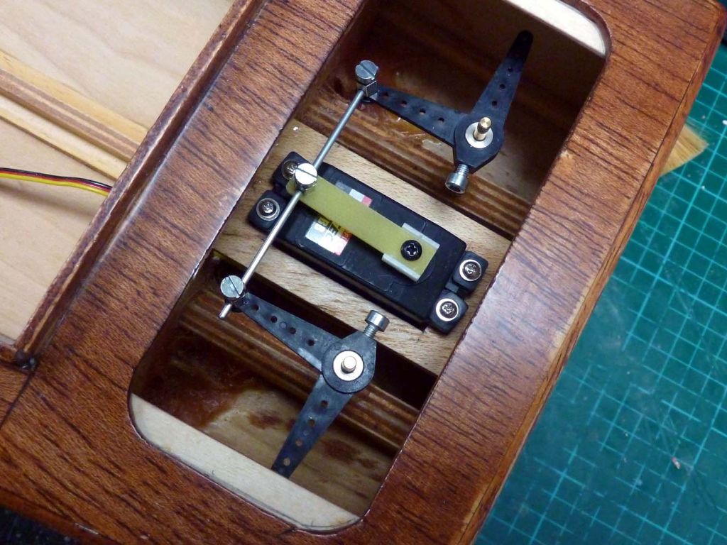
                                                That's a lot of linkages and rods. How about something simple, along the lines of this?

                                                ellie 075a.jpg

                                                Dave M

                                                #67360
                                                Richard H Dunn
                                                Participant
                                                  @richardhdunn

                                                  Thank you for all the help Guys.

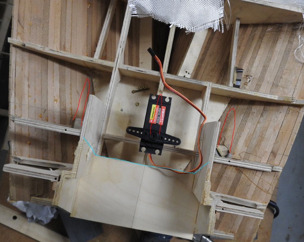
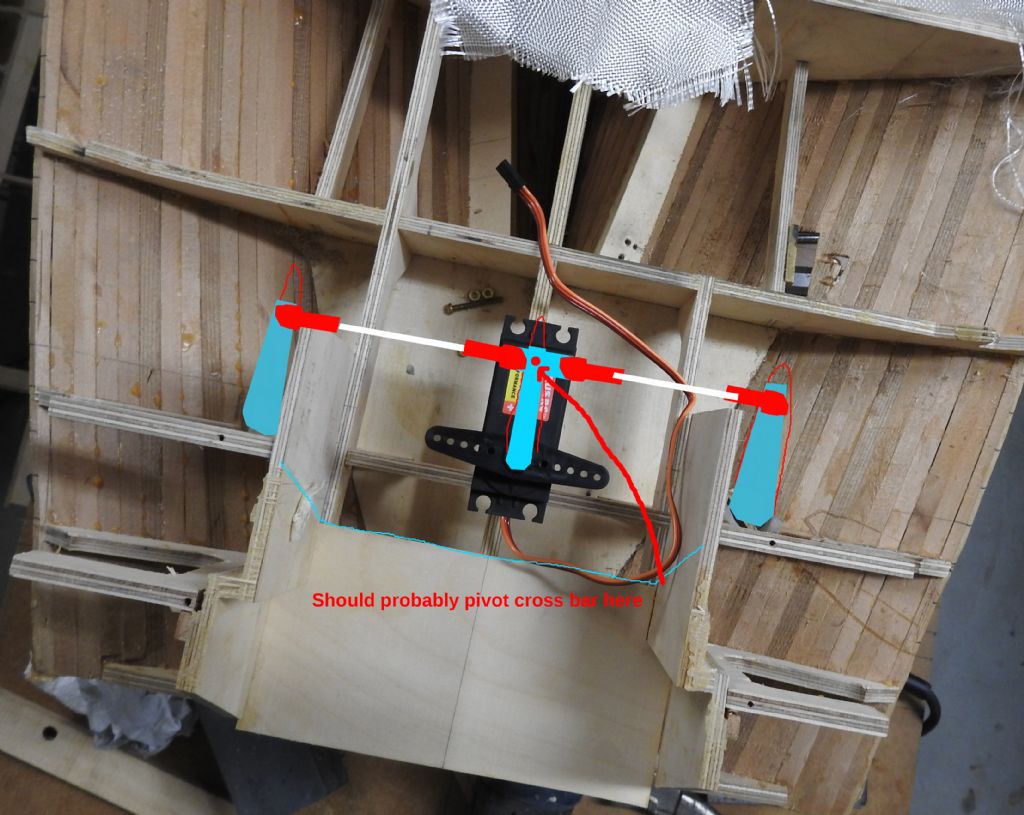
                                                  The image below shows the problem I have, the light blue lines show the back face of the stern door that will be the primary access to this space.

                                                  As you can see it very nearly gets in the way of the gear as the tillers and arms are actually higher than the deck in this area, luckily as I have just checked and photographed I can just fit it in using Dave's suggestion.

                                                  I will have to cut all 3 longitudinal girders away but that's a small price to pay.

                                                  Whats the name of the fittings you have on the servo arms that have holes through them with a grub screws Dave?. just so I can find them online, or did you make them?, I might need those somewhere, I will use ball end tie rod fittings and will make a fitting for the servo arm that has one going Port and the other Starboard.

                                                  dscn1171.jpg

                                                  I propose this setup which is mixture

                                                  arms system.jpg

                                                  At least now I know to make my brass tillers the same length as the ones that come with the servos and the holes for the ball end fittings are 3mm so I can safely fit the rudder posts now

                                                  #67361
                                                  Dave Milbourn
                                                  Participant
                                                    @davemilbourn48782

                                                    Richard

                                                    I think you mean these **LINK**  although you could use four of the Tamiya 3mm ball-and-cup joints as you have drawn.

                                                    Dave

                                                    Edited By Dave Milbourn on 26/08/2016 23:14:30

                                                    #67362
                                                    Richard H Dunn
                                                    Participant
                                                      @richardhdunn

                                                      Yeah that's them thanks, I am using ball cup joints, I have a 16 pack of 3mm ones coming

                                                    Viewing 25 posts - 201 through 225 (of 411 total)
                                                    • Please log in to reply to this topic. Registering is free and easy using the links on the menu at the top of this page.

                                                    Code of conduct | Forum Help/FAQs

                                                    Advert

                                                    Latest Replies

                                                    Home Forums Scratch build Topics

                                                    Viewing 25 topics - 1 through 25 (of 25 total)
                                                    Viewing 25 topics - 1 through 25 (of 25 total)

                                                    View full reply list.

                                                    Advert

                                                    Newsletter Sign-up