TEV Wahine 1/35 Build

Advert

TEV Wahine 1/35 Build

Home Forums Scratch build TEV Wahine 1/35 Build

Viewing 25 posts - 151 through 175 (of 411 total)
  • Author
    Posts
  • #65975
    ashley needham
    Participant
      @ashleyneedham69188

      I have just purchased an electric cycle, and that has a Lithium battery of some sort (LiPo4 I think) of 36V and 10-A/hr capacity, in a nice little smart case …Samsung Cells…..replacement cost £230. estimated 1800+ recharges (2 year warranty on the battery against failure)

      …​Just to put it out there.

      Ashley

      Advert
      #65993
      Richard H Dunn
      Participant
        @richardhdunn

        Hi all.

        Have have spent a week juggling the battery situation and found the best solution is the car battery one.

        Lithiums are going to cost me well over $2000 for the time of 1-2 hours sailing I need and the option of making my own cells is not an option any longer as suppliers will not sell cells to anyone who is not a qualified electronics person.

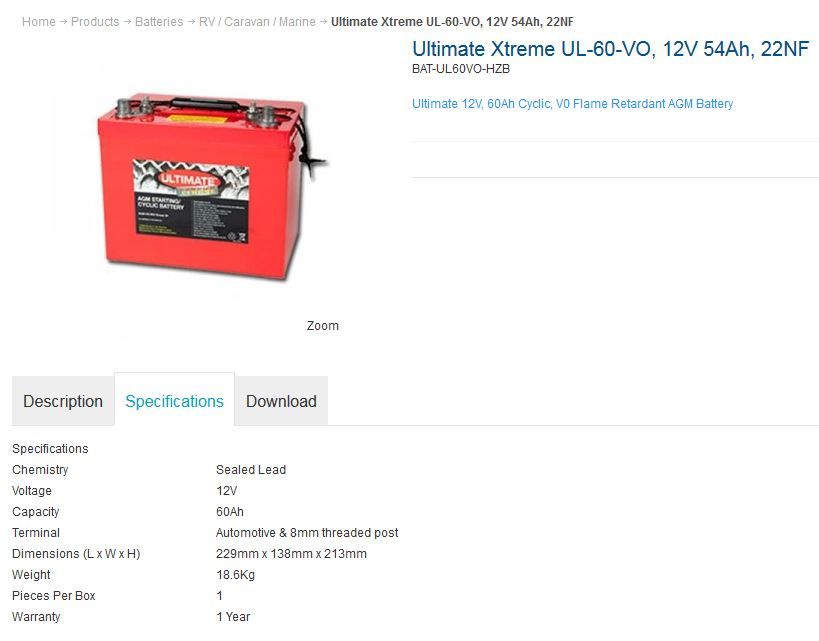
        So I have decided to buy 4 of these.


        Any thoughts about running time on a motor that peaks at 28amps with a normal draw of about 15 amps?.

        I could get 110AH ones to for another $400 total but size is then an issue however I could eventually put another 2 of these in if needed but voltage would then be 36v not 24v, just saying I have room for 6 of these.

        battery.jpg

        Also I have purchased a few more toys over the last few weeks.

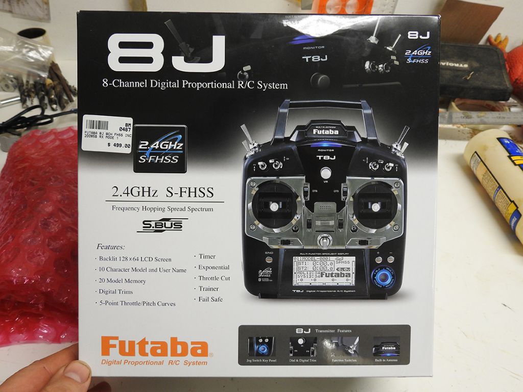
        RC unit

        dscn1043.jpg

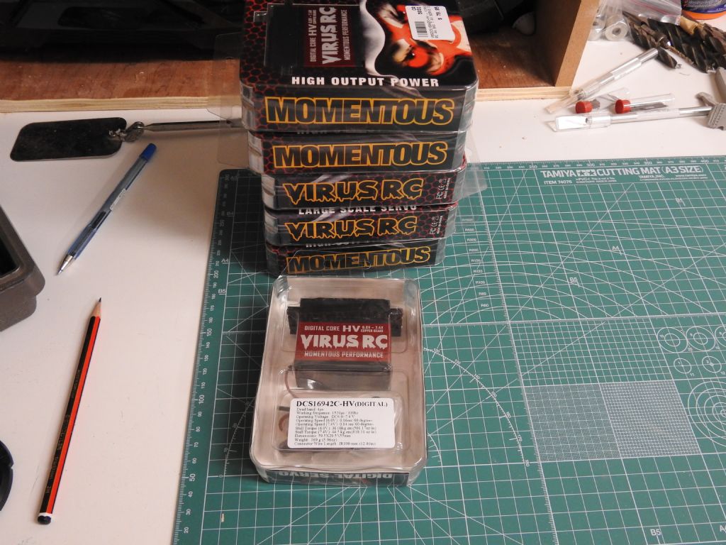
        Servos 6 x 44.5kgs torque

        servos.jpg

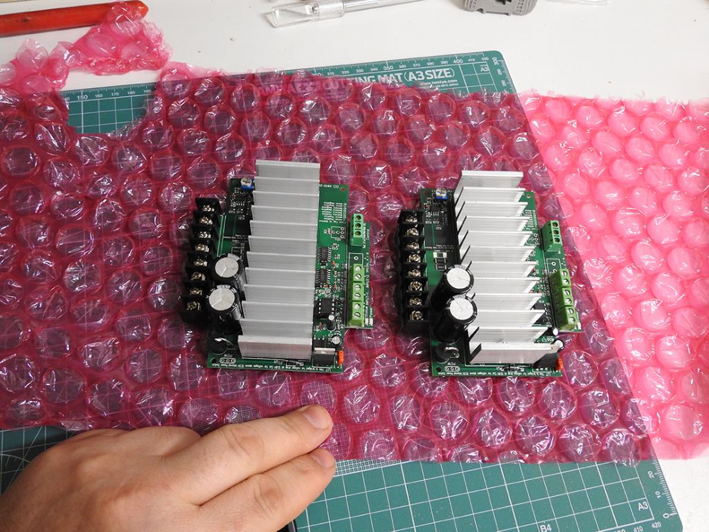
        Here are my speed controllers as well rated to 50amps and bi directional via a pot  that will need to be geared to the servo as it is only 60 degrees

        speed controllers.jpg

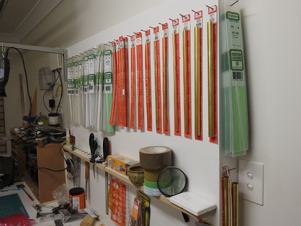
        My styrene collection is growing to, about 10 packs of each of these here, although you can't tell.

        profiles.jpg

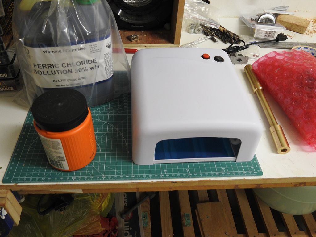
        And now have all my etching stuff except the resist film as it is taking a while to get here.

        etching gear.jpg

        Really looking forward to this part…….


        Gareth if you see this, what sized LED bulbs did you use on your Shemarah 2 masts?

        I need to buy 800 of them and am trying to find a cheap seller.


        Edited By Richard Dunn 3 on 13/06/2016 02:45:16

        #66000
        Gareth Jones
        Participant
          @garethjones79649

          Hi Richard,

          I got all the LEDs for Shemarah from Component-Shop. I think pretty well all of them were the 2.1 mm square ultra bright units. Most of them are wired in pairs or threes with the appropriate resistor for a 12 volt supply.

          I like your choice of transmitter but what are you planning to use those high power servos for? I have to admit your workshop is tidier than mine. I just have my styrene strip and brass sections stuffed into jam jars, albeit separated into tube, strip and other sections.

          Gareth

          #66023
          Richard H Dunn
          Participant
            @richardhdunn

            Thanks Gareth

            The Servos, well I needed a high power one for the rudders because First of all they are are twin rudders, 35 degrees each way, and With the amount of possible resistance from the props which are 104mm in diameter remember I was unsure how much stress they would be facing, I just got the biggest we can get over her and the price was really good, I pain $79.00 each for them.

            6 servos needed for

            Rudders x 1

            Bow Rudder x1

            Motor Throttles x 2

            Bow Thruster x 1

            Stern Thruster x 1

            I will get the remote switches for lights etc so I can have Navigation,Outdoor and internal lights on 3 channels.

            The other stuff like radar will all be just a switch on board ship and run via a tiny motor 5mm in diameter inside rudder pedestal.

            Here is a night shot showing how many darn lights their are in this ship, and why I need so many LEDs, and Flouro tubes.Gareth I think you will feel sorry for me………… 50 approx of those to make for deck heads.

            I might from China as i can get 100 for a good price, I normally wouldn't but with needing so many……….

            Back on page 10 about 2/3 of the way down some can be seen.

            Has anyone used the yellow water clear ones and do they have a subtle yellow light? like below.

            night shot.jpg

            Here is a shot of the the typical Superstructure layout and components, the deck lights can be clearly seen and the conduit that links them as well.

            I have hundreds of shots like this of the ship and the wreck.

            My first thought is to etch the bases and fold them up and solder them, the lens I might have to vacuum form from clear plastic, the lights are 11 x 7 mm.
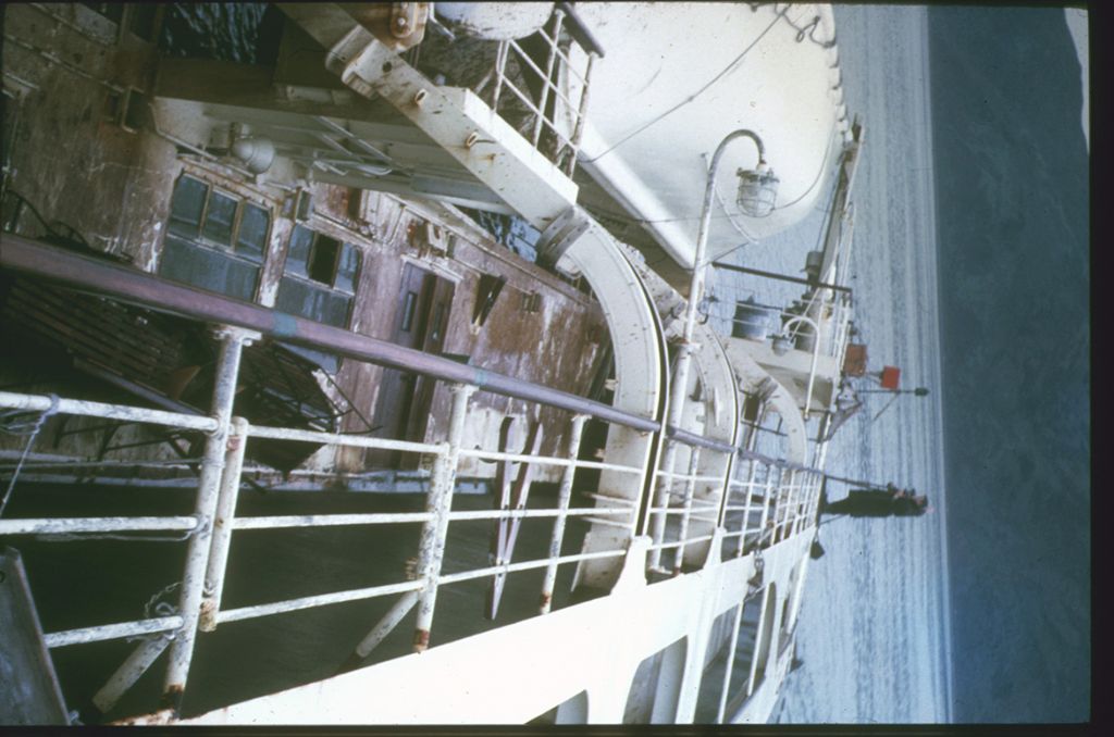
            lights and conduit.jpg

            #66025
            Richard H Dunn
            Participant
              @richardhdunn

              I will buy white LED's and paint them with a custom clear paint to achieve the correct colour, it seems they don't get hot enough to prevent painting

              #66214
              Richard H Dunn
              Participant
                @richardhdunn

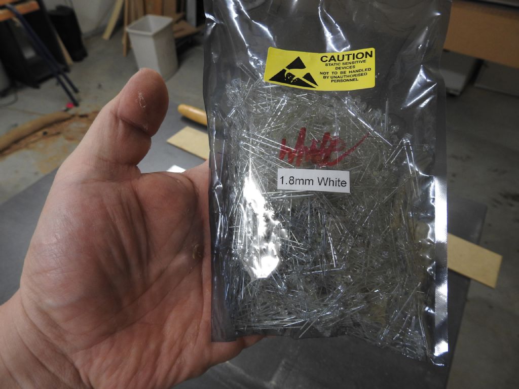
                My LED lights arrived last week.

                1000 x 1.8mm lights

                dscn1060.jpg

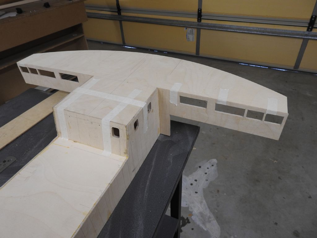
                Work on the Bridge happening now,I am building it around the roof which needs to come off until the end so the inside can be fitted out which is why the roof sits in rebates.

                The windows in the aft section are the radio and chart rooms.

                The holes are all oversize 2mm all the way around to fit the 2mm thick perspex glazing, the superstructure covering will then lay over that with the correct window sizes and frames rigol etc.

                dscn1058.jpg

                Edited By Richard Dunn 3 on 27/06/2016 05:03:14

                #66347
                Richard H Dunn
                Participant
                  @richardhdunn

                  Hi everyone

                  I have been building the last remaining superstructure parts and have almost got the whole ship boxed out.

                  I have started to line the decks with Formica laminate where it is ready, to simulate the SemDek rubber compound applied to the steel, a very nice choice by the way as it paints well and is incredibly hard wearing and hard to damage once epoxied onto the ply

                  In the shot below you can see it applied to the fan room roof and also I am fitting a piece for the aft half of the fore deck.

                  The fan room will lift off for access to fore peak.

                  dscn1072.jpgdscn1073.jpg

                  dscn1074.jpg

                  The bridge is also boxed out now to and ready to be sanded,trimmed and sealed ready for Styrene plating.

                  Again all windows are 2mm all around bigger than finall size 20 take the 2mm thick perspex glazing.

                  dscn1071.jpg

                  dscn1076.jpg

                  And lastly the funnel frame shown upside down is being made ready to be bevelled and have the .4mm ply laminated around its shell.

                  The box makes it strong,easy to align ribs and provides the uptake for the various tubes.

                  dscn1070.jpg

                  #66650
                  Richard H Dunn
                  Participant
                    @richardhdunn

                    Here are some update photos for the progress.

                    It has been slow as of late due to work and being sick

                    dscn1094.jpgdscn1095.jpg

                    I broke my last 1/8 router cutter on the windows so template will be staying there until new one comes.

                    dscn1096.jpg

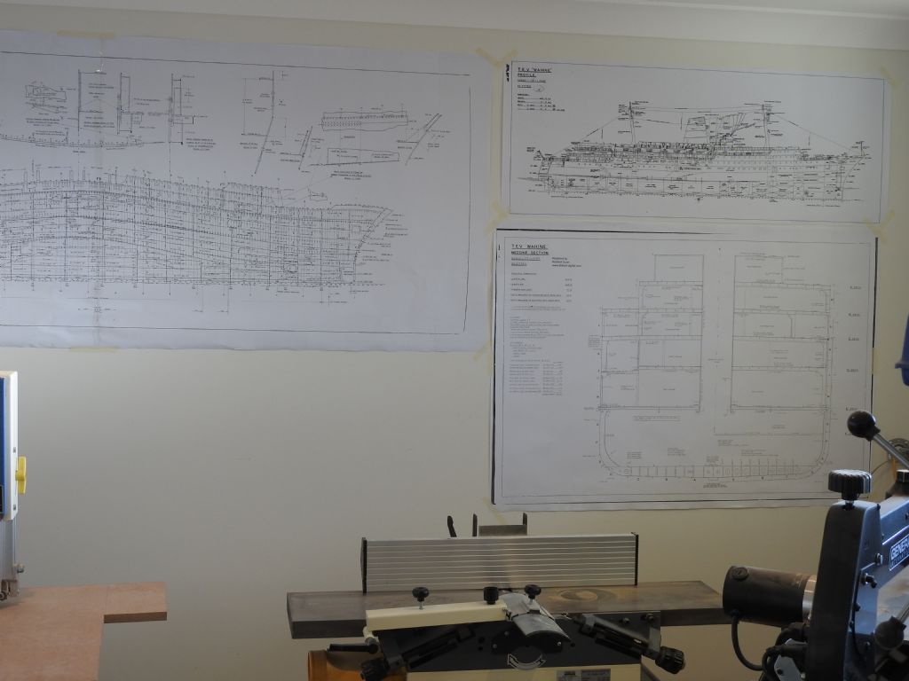
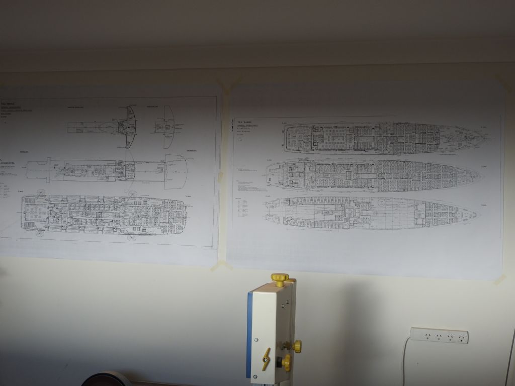
                    I started hanging reference plans so I don't have to keep walking dust into house to check things, also put up all the good photos as well.

                    dscn1097.jpg

                    dscn1098.jpg

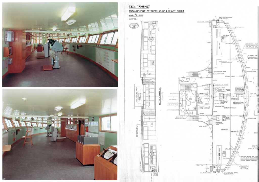
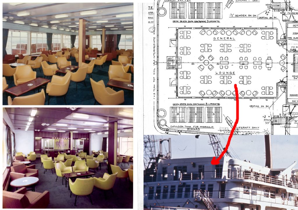
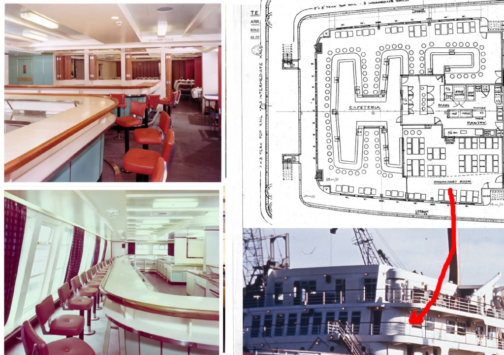
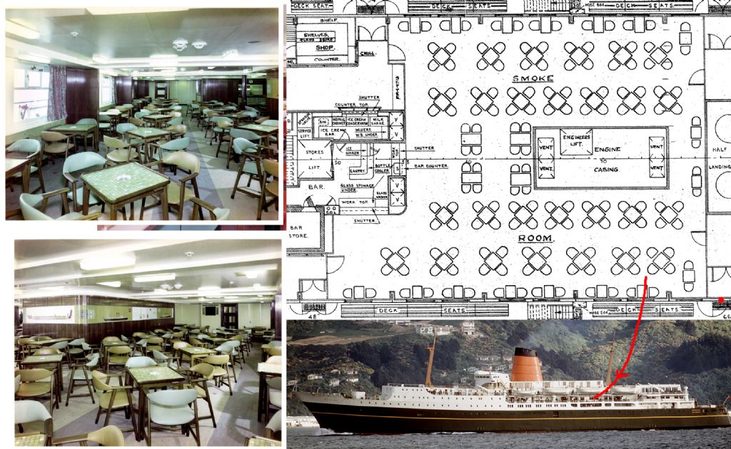
                    I have decided I need to model the interior in 4 places that  I think it will be visible.

                    Bridge

                    bridge.jpg

                    Aft Lounge

                    aft lounge.jpg

                    Cafeteria

                    cafeteria.jpg

                    Smoke Room

                    smoke room.jpg

                    These windows are 40 x 30mm so think it has to be, and you can see clear across ship as well.

                    Edited By Richard Dunn 3 on 20/07/2016 03:52:40

                    #66879
                    Richard H Dunn
                    Participant
                      @richardhdunn

                      Ok so If someone could give me some advice or point me to somewhere to research this.

                      Wiring looms for my servos etc, I have My rudders and Lateral thrust units at the stern and my Bow rudder and lateral thrust unit in the bow with a receiver midships, the space between them is about 2m, is that a problem as far as power dropping and if so how do you avoid it?.

                      Cheers in advance

                      #66881
                      Dave Milbourn
                      Participant
                        @davemilbourn48782

                        Richard

                        I was recently asked to repair a unit which the owner had modified by adding 1m of very thin wire to the leads between the receiver and the unit (which was a speed controller). I wondered if the voltage drop could be contributing to the problem he was having so I measured it. I was surprised to find it was less than 0.1v.

                        I would suggest that you use a 6v supply for your receiver anyway. It's probable that the rudder servos will require their own power supply i.e. independent of the receiver, so you could fit a suitable NiMH battery at each end of the boat to provide that. As regards the main power for the thruster motors (which I assume you're tapping off the main motor batteries) I reckon that as long as you use sensible-sized wiring e.g. 12 or even 14AWG silicon-covered multi-strand then you'll have no significant voltage drop over that distance. The main motors are rated at 28A and 14AWG will easily handle that.

                        Did I read that your speed controllers require a servo to turn a pot, rather than being electronically controlled direct from the receiver?

                        Dave M

                        #66885
                        Dave Milbourn
                        Participant
                          @davemilbourn48782

                          UPDATE

                          I've just been surfing around and found that the DCS16942C-HV digital servos will operate between 6.0v and 7.4v while the 8J receiver operates between 4.8v and 7.4v. That being the case then a 2S LiPo (7.4v) or a 6-cell NiMH battery pack (7.2v) would seem to be the best compromise to power the receiver and the servos without the need for additional batteries for the servos. Component Shop sell servo extension leads up to 1.5m and I'm sure they ship to NZ **LINK**

                          They also sell that lovely silicon cable, too!

                          Dave M

                          #66894
                          Richard H Dunn
                          Participant
                            @richardhdunn

                            Thanks Dave

                            The speed controller is run by a pot yes and the plan is to have a gear wheel fixed to it directly off another one on a servo as the pot is 360 degrees and the servo is 60 degrees so 120 total.

                            The reason I asked was the guys at my model shop highly recommended something called a direct wiring harness.

                            I do plan on having a battery in the bow and stern to run the gear in there but the issue was the distance from the receiver according to them.

                            I just re-measured and the stern is 2.1m and the bow is 1.6m

                            Edited By Richard Dunn 3 on 02/08/2016 02:15:31

                            #66896
                            Richard H Dunn
                            Participant
                              @richardhdunn

                              The Battery pack I bought for this is this

                              Redback 6800mah 7.4V 2S 60C Hardcase Lipo

                              Dimensions 47x26x137mm

                              Which is line with what you suggested anyway……

                              #66898
                              Dave Milbourn
                              Participant
                                @davemilbourn48782

                                Richard

                                Using 26AWG copper wire over 7 feet with a load current of 0.5A the voltage drop would be of the order of 0.3v. For a current of 2A it would be approx 1.1v. Using 22AWG cable the corresponding values are 0.16v and 0.65v. To get an accurate estimate (??) then you would need to measure the current drawn by the servos on load @ 7.4v. These are digital servos and will take more current than non-digital types but I doubt if you will need anything approaching their maximum output torque! There is a voltage drop calculator here **LINK**

                                I'd suggest you check the rotation angle of the pots – most are 270° end to end. You could remove them and use remote sliders if you want to avoid gears and consequent backlash. e.g. **LINK**

                                Dave M

                                #66900
                                Richard H Dunn
                                Participant
                                  @richardhdunn

                                  Thanks for that, I had no idea you could get those to be honest,.it would be much easier to hook up for sure.

                                  I would like to avoid gears as much as possible!!

                                  #66901
                                  Richard H Dunn
                                  Participant
                                    @richardhdunn

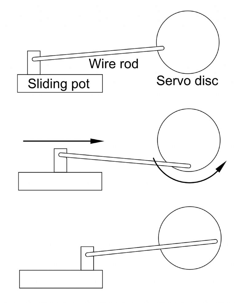
                                    the pots for the speed controllers are not mounted to the board anyway they get wired to it so that would be much simpler. How do you move a slider with a servo arm that moves in an arc? or am I thinking about it all wrong

                                    #66903
                                    Dave Milbourn
                                    Participant
                                      @davemilbourn48782

                                      Not wrong – just not sideways.

                                      How about this?

                                      What's the value of the pot's resistance?

                                      slider mechanism.jpg

                                      Edited By Dave Milbourn on 02/08/2016 12:51:08

                                      #66909
                                      Richard H Dunn
                                      Participant
                                        @richardhdunn

                                        Ah a cam system, the pot is a 10k.

                                        I have not purchased the pots yet and will do as soon as I know what I need.

                                        I also need to buy small bevel gears for the lateral thrust units but I have that sourced.

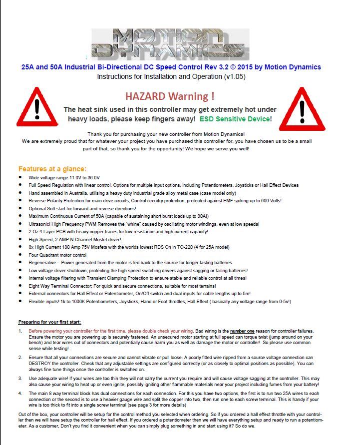
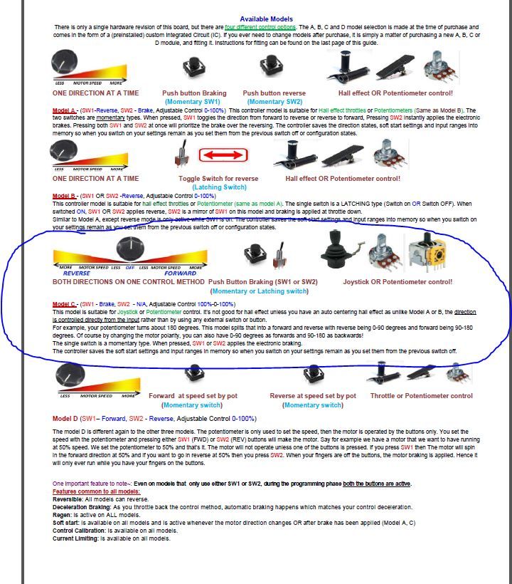
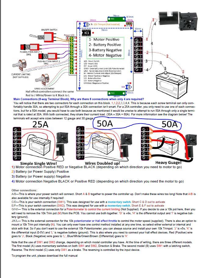
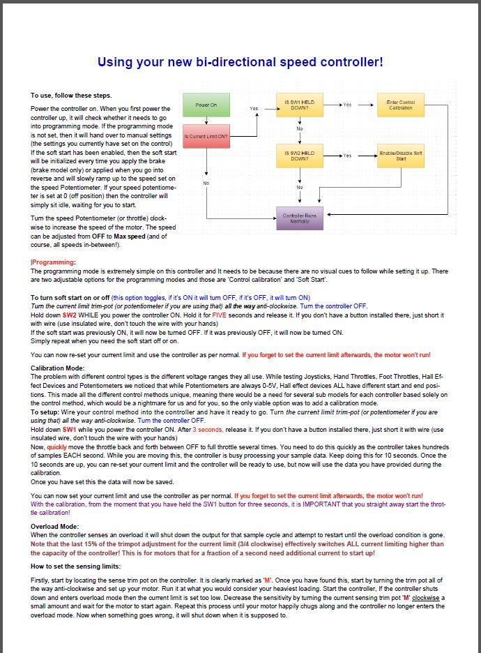
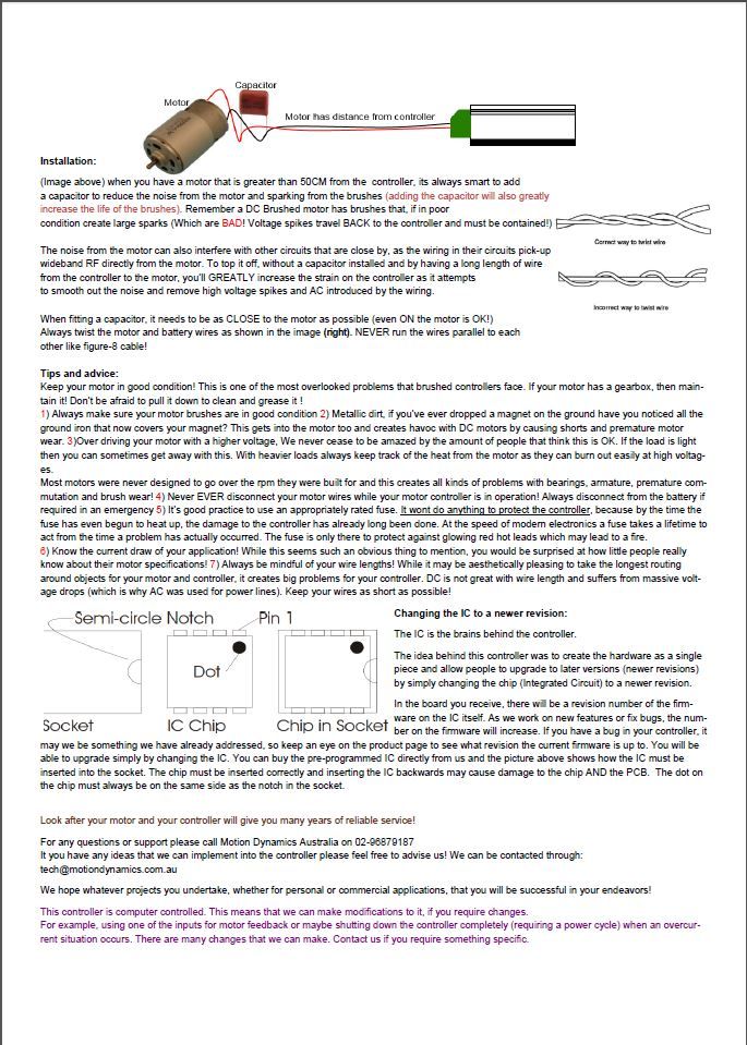
                                        Due to my inexperience with the electronic side of things I have put up the manual from the speed controller.

                                        page1.jpg


                                        page2.jpg

                                        page 3.jpg


                                        page3.jpg

                                        page4.jpg

                                        Edited By Richard Dunn 3 on 02/08/2016 22:35:15

                                        #66910
                                        Dave Milbourn
                                        Participant
                                          @davemilbourn48782

                                          I'll have a good look at these tomorrow. I've downloaded them so I won't have to squint so much!
                                          11.20pm here – goodnight.

                                          DM

                                          #66911
                                          Richard H Dunn
                                          Participant
                                            @richardhdunn

                                            Cheers

                                            Yeah early morning here in Australia

                                            I actually just watched the video they have put up  and 22 mins in they go over the setup and programming for type C , not nearly as complex as I thought…..

                                            https://www.motiondynamics.com.au/12v-36v-dc-speed-control-bi-directional-50a-pcb-model.html

                                            Easier than reading.


                                            Edited By Richard Dunn 3 on 02/08/2016 23:41:58

                                            Edited By Richard Dunn 3 on 02/08/2016 23:42:10

                                            #66913
                                            Dave Milbourn
                                            Participant
                                              @davemilbourn48782

                                              Can you obtain suitable sliders locally? I can get them over here with as little as 15mm travel end-to-end, and as much as 100mm! I'd suggest 30mm would be a good compromise between the degree of speed variation available and physical size.

                                              DM

                                              #66915
                                              Richard H Dunn
                                              Participant
                                                @richardhdunn
                                                #66917
                                                Dave Milbourn
                                                Participant
                                                  @davemilbourn48782

                                                  I've used Digikey UK in the past and they are first rate. I'd suggest the Bourns one because I also know this manufacturer's goods – PTA3043-2010CIB103-ND. From reading the datasheet it's the right resistance and taper (linear) so it should do the job. It looks like they have plenty in stock…

                                                  Dave M

                                                  #66919
                                                  Richard H Dunn
                                                  Participant
                                                    @richardhdunn

                                                    Thanks heaps for that advice

                                                    #66935
                                                    Richard H Dunn
                                                    Participant
                                                      @richardhdunn

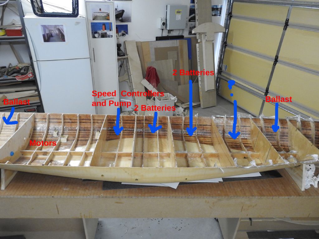
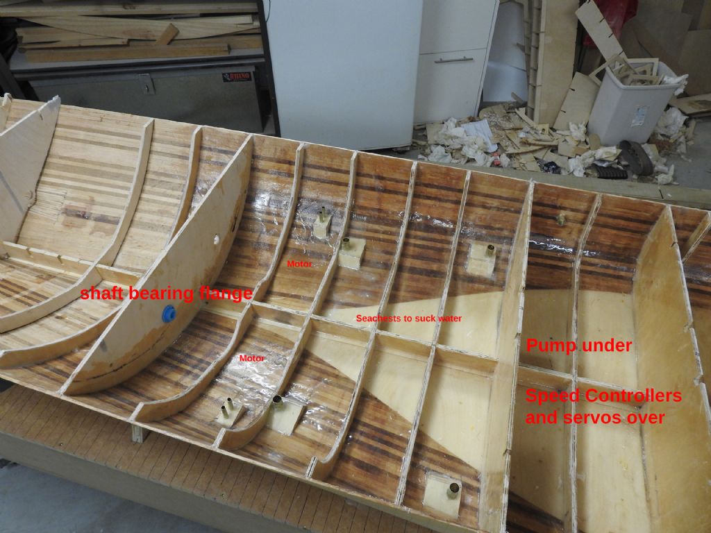
                                                      So last weekend I did the horrible job of separating the topsides from the bottom at the chine, as you may remember it was always the plan and to then remove the intricate temporary framing once the hull was able to hold its own shape.

                                                      Well here it is, the glassing of the inside has been done with 200 gm cloth and is now as strong as all heck having been done both sides of the cedar planing core.

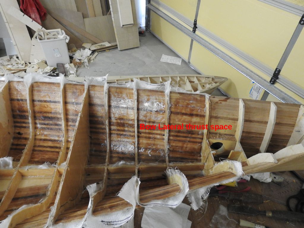
                                                      The glassing here is tacking off before weave fill pass and will be trimmed with Dremel when cured

                                                      I will then go to work installing the Propeller shafts, rudders and lateral thrust unit before gluing the topsides and glassing the joint.

                                                      Then it will be time to start the modelling, up to now its more boat building……

                                                      space allocation.jpgmotor compartment.jpgbow lateral thruster space.jpg

                                                    Viewing 25 posts - 151 through 175 (of 411 total)
                                                    • Please log in to reply to this topic. Registering is free and easy using the links on the menu at the top of this page.

                                                    Code of conduct | Forum Help/FAQs

                                                    Advert

                                                    Latest Replies

                                                    Home Forums Scratch build Topics

                                                    Viewing 25 topics - 1 through 25 (of 25 total)
                                                    Viewing 25 topics - 1 through 25 (of 25 total)

                                                    View full reply list.

                                                    Advert

                                                    Newsletter Sign-up