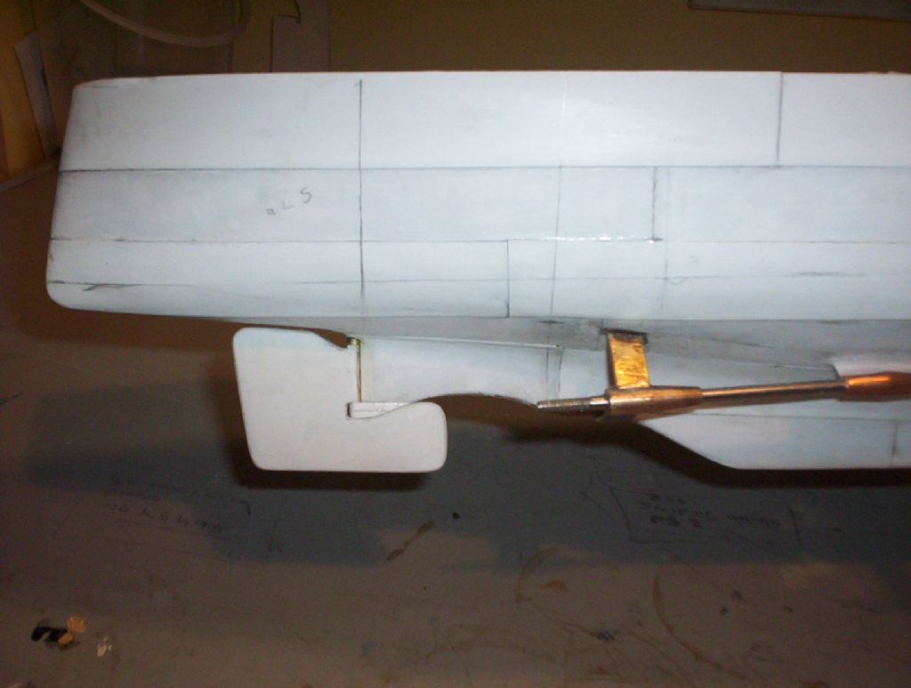
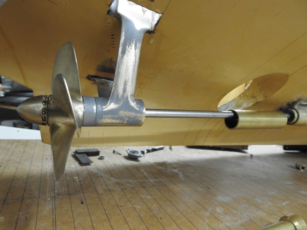
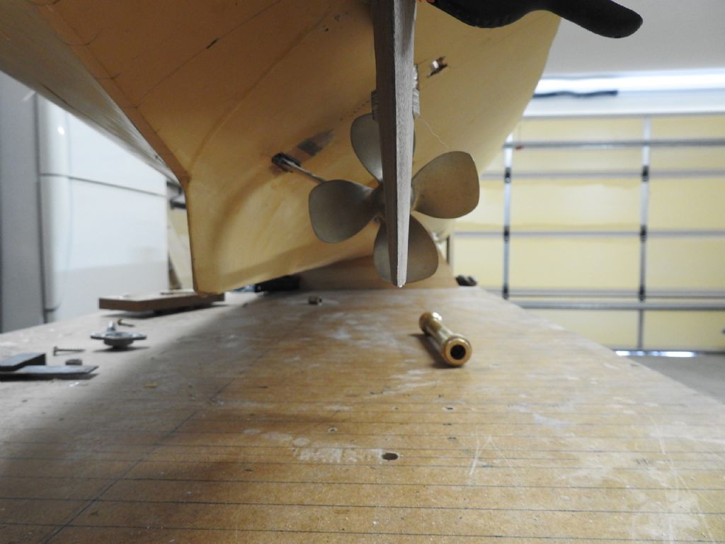
Here are some images of the first shaft installed with an A bracket and Rudder.
This has taken ages as I had to wait weeks for the bearings to arrive and having to wait 24 hours every time I epoxy a part so as not to disturb alignment.
Props spin freely for about 4 turns on their own.
Motor room BHD bearing that locks on to shaft.
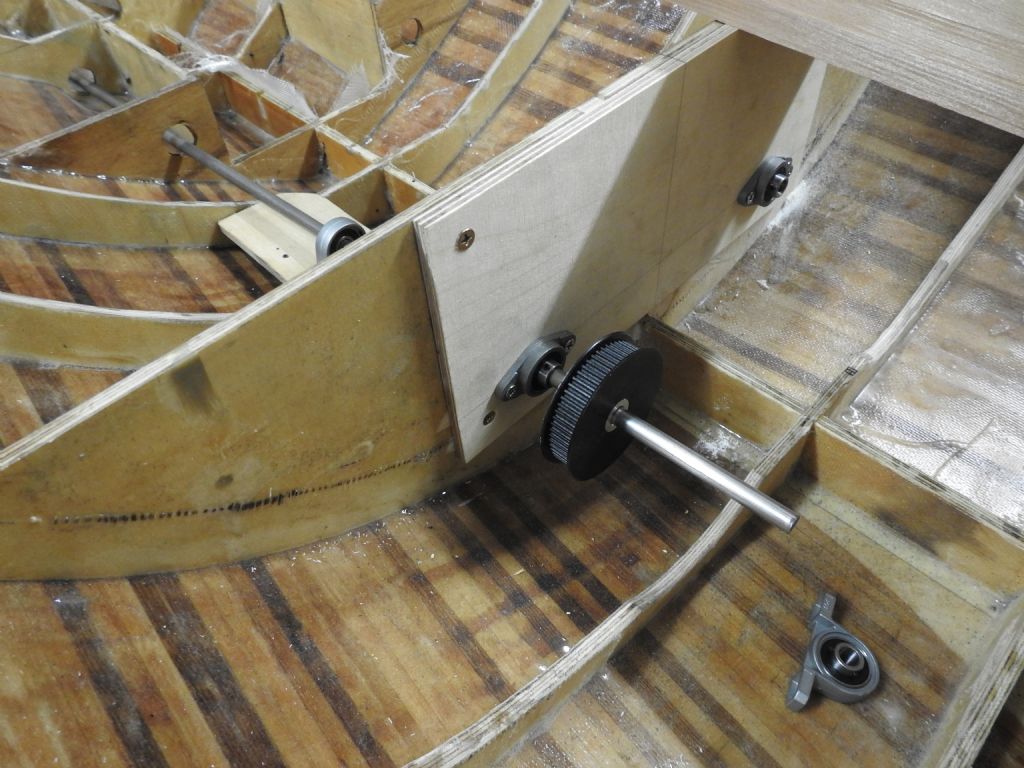
Below, Thrust bearing mounted on stool, also locks onto shaft.
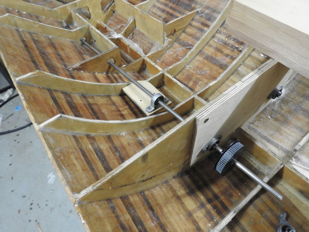
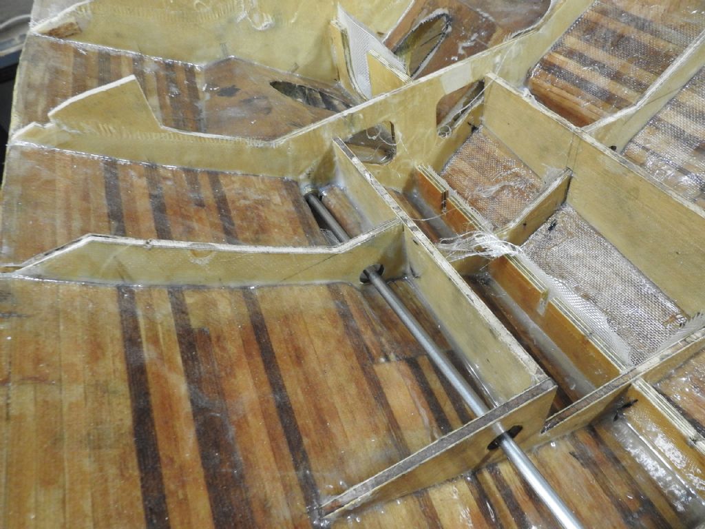
Inside face of shaft bossing showing one of the ball bearings, not easy to see though
The fitted Prop and rope guard between the prop and A bracket. bracket is shaped and epoxied on ready to fit bolts.
Once the hull plating gets bonded on the result should look a lot tidier.
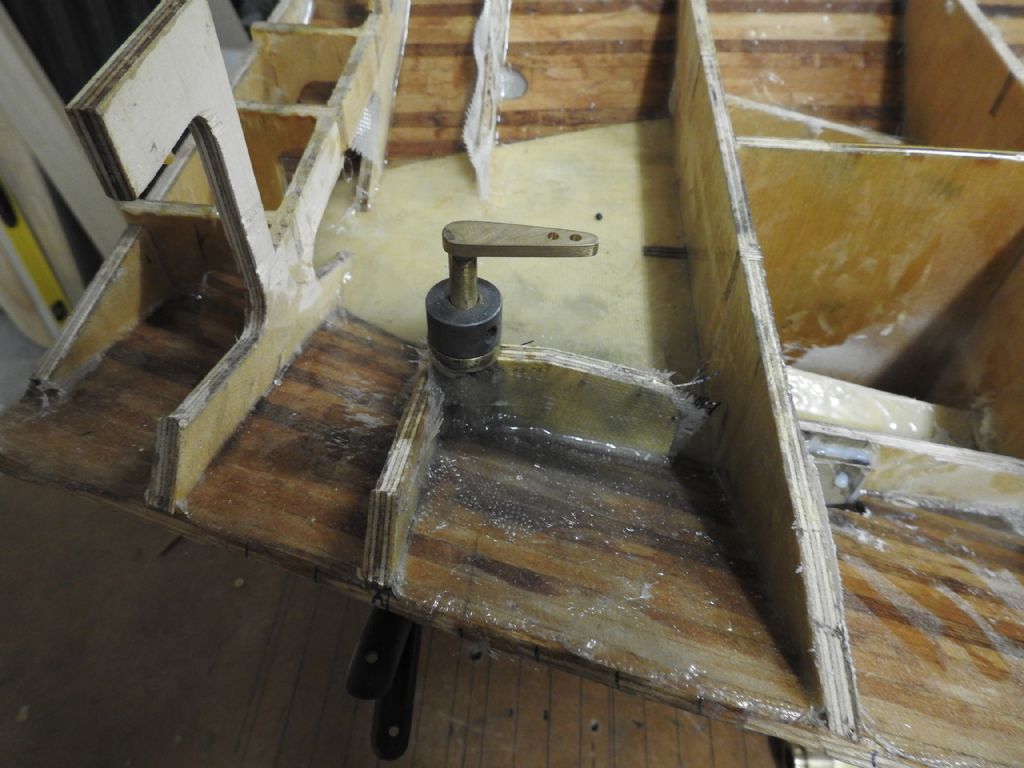
Below is the upper bow rudder bearing
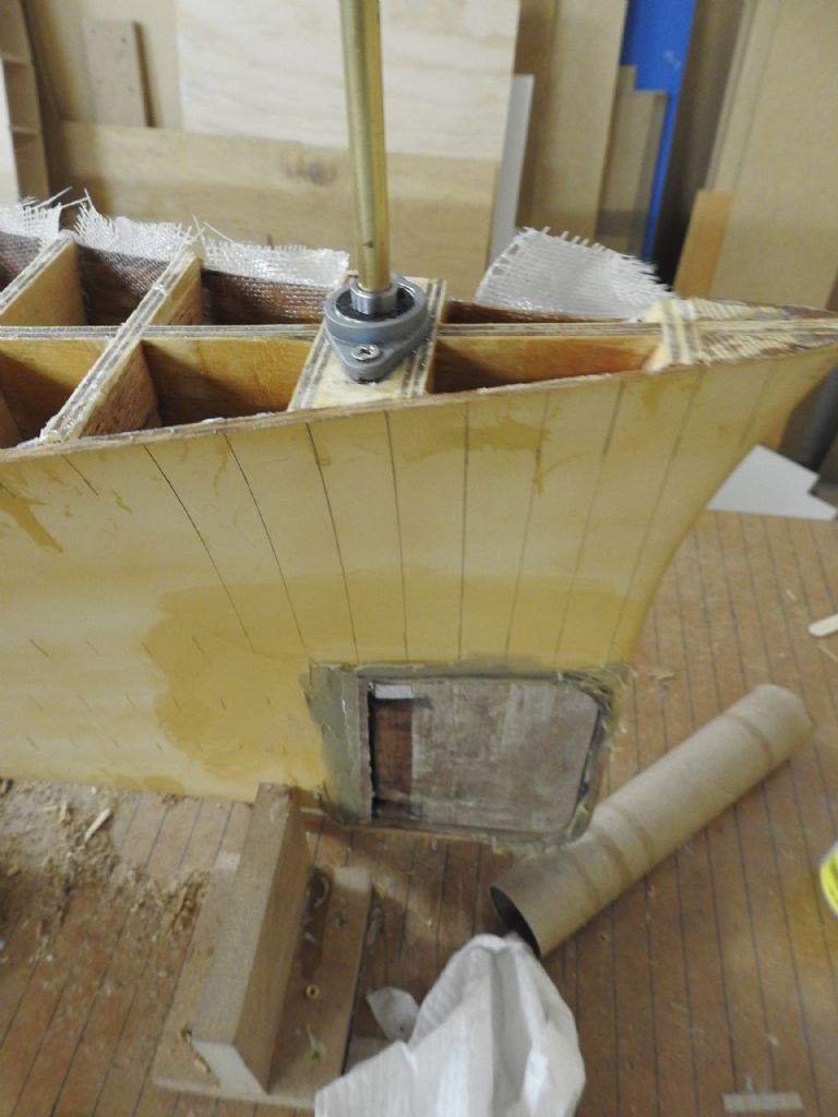
This shot shows the rudder surround and bushes installed in the rudder, the protruding threads are where the rudder shaft and lower pintle bolt on, The upper one is removed by undoing nut and pulling the shaft up and the lower one is removed by undoing nut and letting the pin drop out the bottom, just like the real thing
The rectangular holes will be lined in Styrene and only open to the port side as per plans.
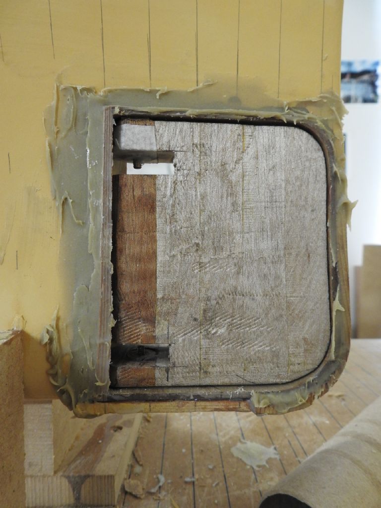
A view of the upper bushing if you look inside the recess it can be seen, it was knurled on lathe and bonded into rudder so it can't come loose.
The laminated curved back plate of the rudder recess can be seen.
Now the bow and forefoot can be shaped to final lines of bulbous bow.
Rudder is currently sitting too low as I have a thick brass washer wedged in the top gap to centre the upper shaft while upper bushing was bonded in place, clearance of 1mm all around will be the final gap
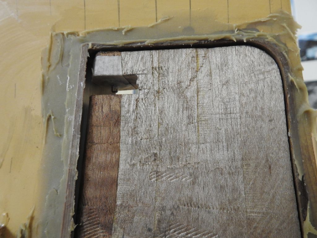
The upper recess can be seen here in this poor image.
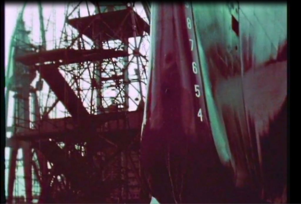
Edited By Richard Dunn 3 on 11/10/2016 00:44:46
Edited By Richard Dunn 3 on 11/10/2016 00:46:30
Also the Rudder assembly bonded and glassed in.
Edited By Richard Dunn 3 on 11/10/2016 00:53:31
 Ray Wood 3.


