Prototype build of ELLIE

Advert

Prototype build of ELLIE

Home Forums Scratch build Prototype build of ELLIE

  • This topic is empty.
Viewing 25 posts - 726 through 750 (of 1,441 total)
  • Author
    Posts
  • #44492
    Paul T
    Participant
      @pault84577

      Bob

      Thank you for the feedback, I had already considered all of your points when updating the designs but in answer to your questions please see below.

      The keel is 6mm to save on material costs [as the frames are also 6mm they can all be cut out of the same sheet.]

      I don't intend to deepen the keel to protect the propeller as this would spoil the design but it is up to the individual builder if they wish to retro fit something.

      The rudder stem has a wooden block to support it, unfortunately the designs that you have didn't include this detail.

      I hope this fully answers you questions but if not or if you have any other questions then please ask.

      All the best from the comfy drawing office (deep leather recliner chairs with espresso machine to hand)

      Paul

      Advert
      #44511
      Bob Abell 2
      Participant
        @bobabell2

        Thank you Paul

        Made some progress lately

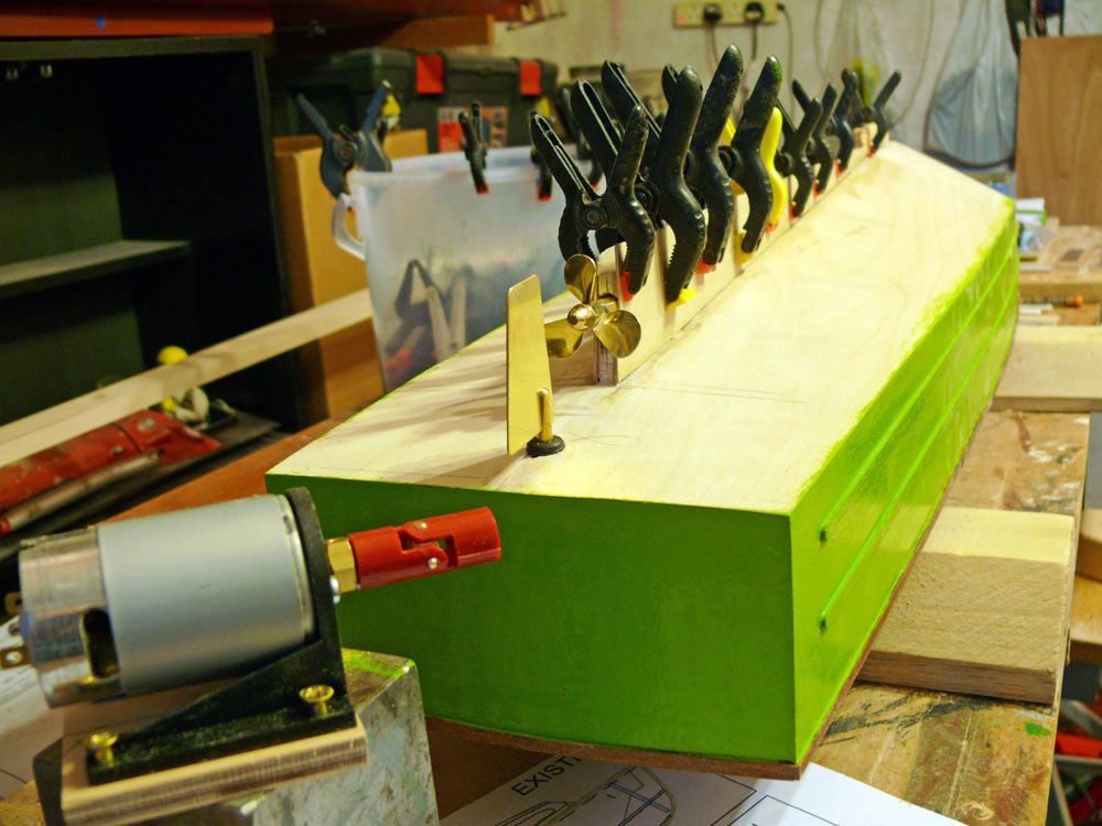
        Fitted the propshaft and added the keel side cheeks

        Fitted the commercial rudder

        propshaft and prop.jpg

        With the 555 motor in the foreground

        Still in the process of sorting the new PC colours out

        Bob

        #44562
        Paul T
        Participant
          @pault84577

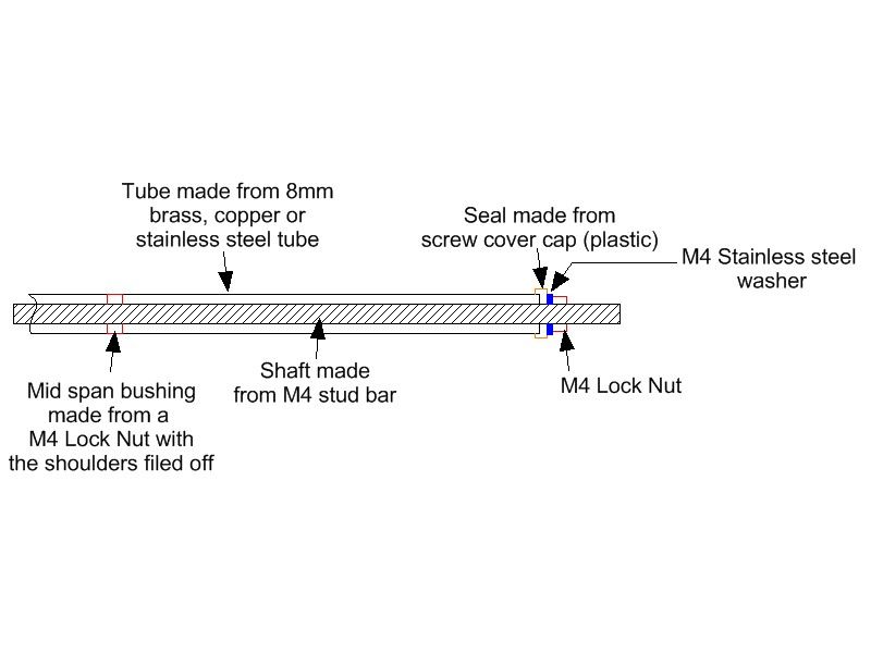
          One of the problems with building the triple motor version is the cost of the equipment, I can't do much about the motors themselves so I turned my attention to making my own propshafts.

          propshaft 1.jpg

          This one has an 8mm dia tube, is 360mm long with an M4 shaft and has a mid span bearing and cost less than £2 to make

          Paul

          #44563
          Bob Abell 2
          Participant
            @bobabell2

            Hello Paul

            I wouldn`t think a mid span bearing is really necessary, for such a short length?

            I would like to see the drawing, please…..Out of curiosity

            It would look nice with three props though!

            Bob

            #44568
            Paul T
            Participant
              @pault84577

              pauls propshaft.jpg

              #44570
              Bob Abell 2
              Participant
                @bobabell2

                Time to layout the gear……An important event!

                There are a few things to watch out for!……..And no doubt,certain forum members will have something to say about this subject!

                I like to use a single board and mount the gear on top, with all the wires out of sight, underneath
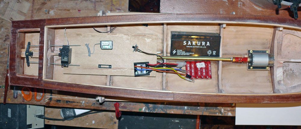
                plan view.jpg

                The rudder servo is on the left, not far from the rudder…..Obviously

                Next comes the receiver, with the On/Off switch below it

                Next right is the Electronic Speed Controller……..Note……..Some distance away from the Reciever, to avoid interference…..Above, is another On/Off switch, which is part of the ESC

                Next comes the main battery and below that is the Reciever battery and are on the approx. centre of gravity position. The batteries can be moved about, fore and aft for balance adjustment

                On the extreme right is the motor drive

                In order to achieve a simple looking layout, a few extension cables may be required

                That`s about it…….Nothing is fixed at the moment and can be moved about, pending constructive comments

                Bob

                The base board will be screwed to blocks glued to the hull, for easy maintenance

                #44574
                Dave Milbourn
                Participant
                  @davemilbourn48782

                  Bob

                  1. You don’t need a separate battery pack or On/Off switch with that particular speed controller because it is fitted with Battery Eliminator Circuitry (BEC). If you do wish to use a separate battery then you will need to follow the directions in the Viper Instructions about removing the red wire from the plug which connects the ESC to the receiver. This is important!
                  2. You will have a very noticeable list to port if you fit the main battery there. It would be best positioned on its side, lying centrally across the hull (not along the length). This is because the majority of the weight of the battery is in the base.
                  3. You would be best advised to fit the ESC just ahead of the motor. This will keep the length of the big fat power leads down to a minimum and also well away from the receiver and aerial wires.

                  I wish I had the luxury of all that space in Sea Spray. The open cockpit well takes up over 60% of the available space inside the hull, and I have two of everything to fit! I'm currently still applying the varnish to the deck; I think it's had 8 or 9 coats so far.

                  Dave M

                  #44575
                  Paul T
                  Participant
                    @pault84577

                    Dave

                    I wish I had the luxury of all that space in Sea Spray. The open cockpit well takes up over 60% of the available space inside the hull, and I have two of everything to fit!

                    Its keeping you busy and out of Liz's hair, besides you needed a challenge worthy of your technical skills, or would you rather build the Red Leader version where shoehorns have been replaced with big hammers.

                    Only 9 coats………… a long way to go then.

                    Paul

                    #44577
                    Bob Abell 2
                    Participant
                      @bobabell2

                      Thanks Dave

                      I knew you would be getting involved……lol

                      Haven`t read the Viper instructions yet, but I do remember snipping off an orange wire a few years ago!

                      I couldn`t believe such a drastic step!

                      If I position the battery across the hull, it`s got to clear the propshaft and will be quite high

                      I will use the BEC feature

                      More later………Off to the Dentist now!

                      Bob

                      #44580
                      Dave Milbourn
                      Participant
                        @davemilbourn48782

                        Only 9 coats………… a long way to go then.

                        Ten now. Just graduated onto 600 Wet and Dry, used wet. 1000 grit next.

                        Bob
                        It's not mandatory to fit SLA batteries in all model boats. They are more useful in tugs – where ballast is required – than they are in launches which need far less ballast (if any at all).. You already possess two 12v NiMH packs, either of which would sit along the top of the keel with its CG lower than that big lead brick in the picture.

                        BTW you don't have to cut the wire – See "Disabling BEC ESCs" here http://www.action-electronics.co.uk/wd.php
                        Hope your dentist is cheaper than mine………………..
                        Dave M

                        Edited By Dave Milbourn on 23/10/2013 12:19:22

                        #44582
                        Bob Abell 2
                        Participant
                          @bobabell2

                          Thanks Dave

                          Are you suggesting using my two NiMH….One on each side @12v

                          Using one as the driver and the other….a counter balance?

                          It`s a good idea!

                          Bob

                          #44583
                          Dave Milbourn
                          Participant
                            @davemilbourn48782

                            Bob
                            You could connect both together in parallel to double the battery capacity. You'd need a device such as the ACTion P103 to prevent one discharging into the other.
                            I suggest using just one at a time. The motor you have chosen draws little current so the pack (which is 4600maH from memory) will last a fair time. You can take the other pack (fully-charged) to the lake to change over if you want a longer session or, as you say, fit the second pack into the model as a counterbalance and simply swap over the leads from the ESC.
                            Good idea? I'm full of 'em!
                            Dave M

                            #44629
                            Bob Abell 2
                            Participant
                              @bobabell2

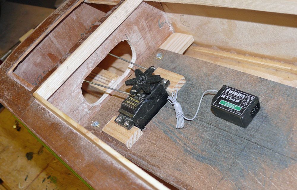
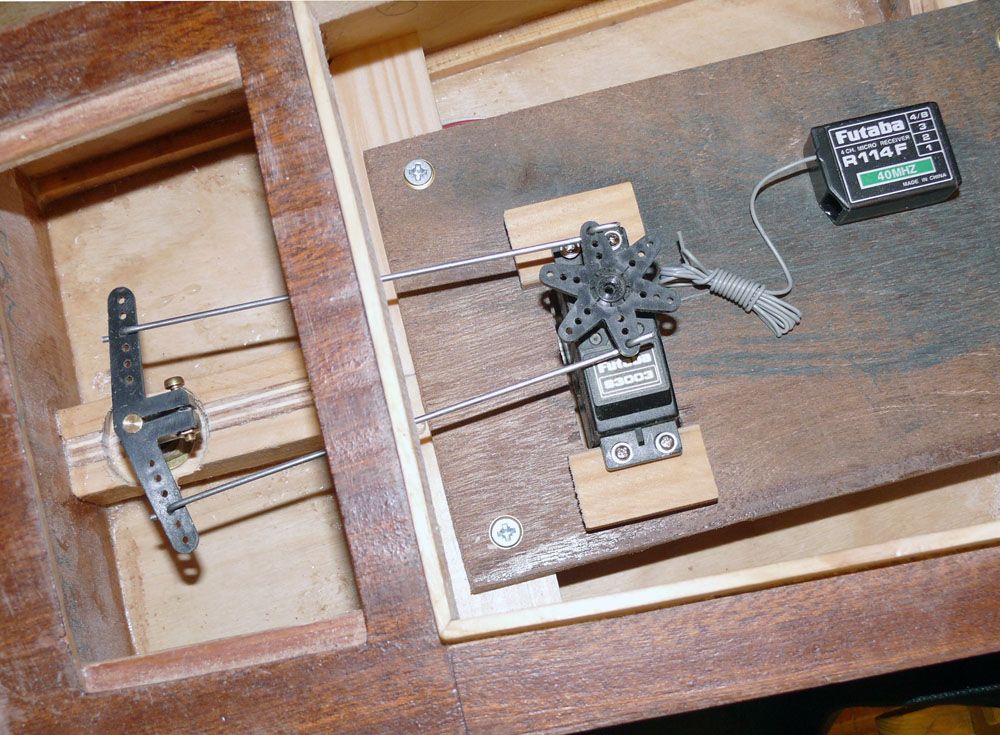
                              Work in progress on the electrickery stuff…..

                              rudder mech.jpg

                              rudder mech-2.jpg

                              The rudder mechanism……Bending the push rods is a tricky job for some Newbies!

                              One trick is to screw the servo base down after bending

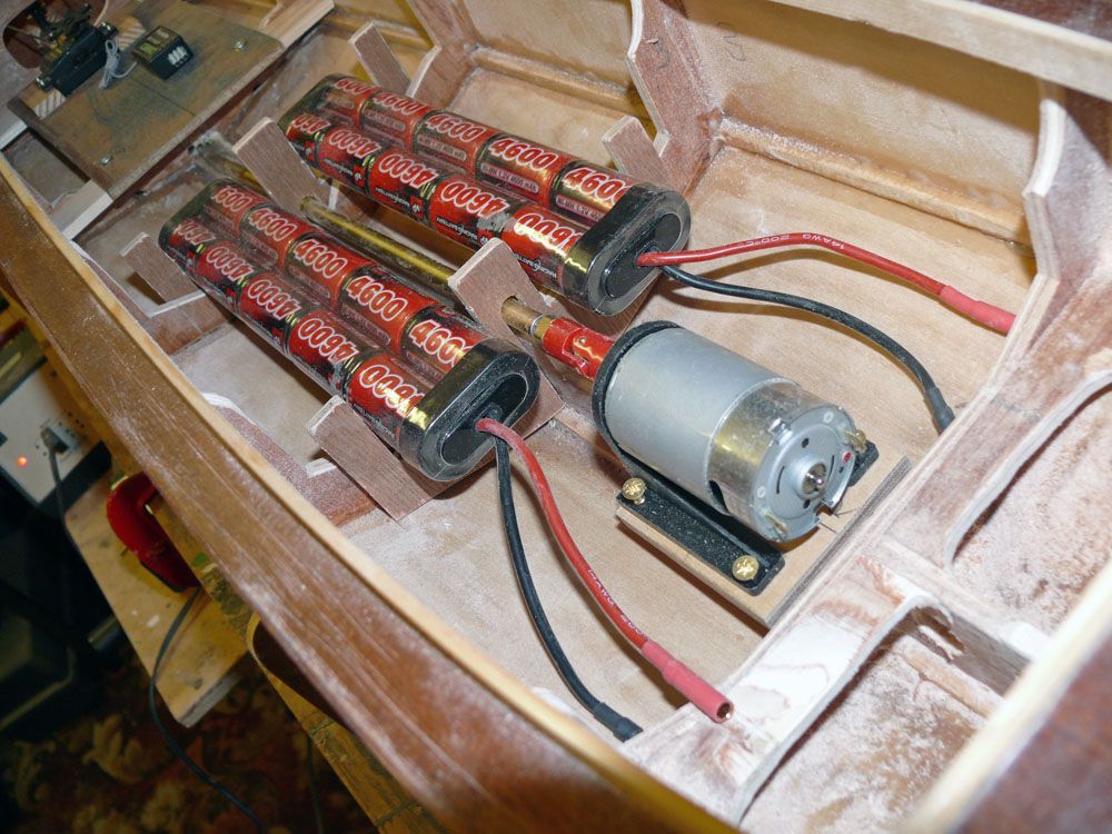
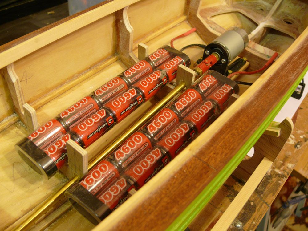
                              battery holders.jpg

                              battery rack.jpg

                              The stick batteries are retained in racks and can be moved forward and aft for some balance adjustment

                              Bob

                              #44630
                              Paul T
                              Participant
                                @pault84577

                                Hello Captain

                                The battery packs do fit in very nicely and with so many cells you should get a weeks boating between charging.

                                For myself I decided to physically check the minor design changes that are associated with the triple engine version and so I am deep into building the Red Leader version and just to keep things interesting I am diagonal planking the hull with 18 x 4mm pine timbers.

                                Paul

                                #44631
                                Bob Abell 2
                                Participant
                                  @bobabell2

                                  Come on, Paul

                                  How about a few pictures, please?…….You too, Dave

                                  Bob

                                  #44632
                                  Dave Milbourn
                                  Participant
                                    @davemilbourn48782

                                    Slow going, Bob.

                                    DM

                                    #44633
                                    Paul T
                                    Participant
                                      @pault84577

                                      Bob

                                      I wish I could post some photos but after years of faithful service my camera has developed a fault so its been packed off to Canon for repair.

                                      When do you think your first sailing will be?

                                      Paul

                                      #44634
                                      Dave Milbourn
                                      Participant
                                        @davemilbourn48782

                                        Bob – an observation rather than a criticism:

                                        I've never understood why some folk use two stiff wire pushrods to connect a tiller. With 1.6mm – 2mm steel wire (bike spokes) it simply isn't necessary because the wire will not bend under the relatively small compression stresses involved. (If you were using chain or some kind of flexible line in a closed-loop arrangement then things would be different).
                                        The added complication is that the distance between the two pushrods must be identical across the tiller and output disc or the system will tighten up as it rotates. At the extreme this could stall the servo or jam the rudder hard over. You also have no opportunity to increase or decrease the rudder throw by using a different hole in either the tiller or disc.
                                        And finally a thought to ponder – the loads on the flying surfaces of model aircraft are much higher because of their much larger area and faster flow of air c/w a water rudder, yet they only use a single solid pushrod.

                                        I rest my case, m'lud.

                                        DM

                                        #44635
                                        Bob Abell 2
                                        Participant
                                          @bobabell2

                                          Dave

                                          I came into model boats via the model aircraft route…..The thread is actually 8 BA

                                          The 1/16" wire came with some nice looking metal 8 BA threaded clevis`s……Ran out of clevis`s years ago…..But habits linger!

                                          But the punch line is………I like it looking strong and chunky

                                          The tiller shape certainly is strange……..Limiting the throw adjustment

                                          Your constructive observations are always welcome

                                          Bob

                                          #44663
                                          Bob Abell 2
                                          Participant
                                            @bobabell2

                                            Making heavy weather of wiring the equipment at the moment

                                            The leaflet that came with the Viper ESC says………

                                            ………".make sure that the orange signal wire is facing inwards"……….eh?

                                            What does that mean?…..please

                                            I guess it refers to the orange wire not being on the outer edge of the Rc

                                            Bob

                                            #44664
                                            Dave Milbourn
                                            Participant
                                              @davemilbourn48782

                                              Got it in one, Bob. Convention is the negative wire (black usually, but brown with these ESCs….) goes to the outside edge of the receiver circuit board.
                                              Post a photo of your installation problem and I'll see what I can do to help. It's probably no consolation to learn that a single screw set-up with BEC is the very easiest system to wire up!

                                              fig 14..jpg

                                              Perhaps fit a Deans connector between the switch and the battery to allow changing over from one pack to the other,

                                              Dave M

                                              #44666
                                              Bob Abell 2
                                              Participant
                                                @bobabell2

                                                Thanks a lot Dave, nice drawing btw

                                                I'll post a picture shortly

                                                Paul

                                                Sorry, just spotted your question about……When will I be ready for a sail?

                                                I'd say in about four weeks

                                                Bob

                                                #44674
                                                Bob Abell 2
                                                Participant
                                                  @bobabell2

                                                  Hello Dave

                                                  What does the on/off switch do on the ESC?

                                                  A fuse is needed somewhere ?

                                                  Bob…….Been awake for hours!

                                                  #44677
                                                  ashley needham
                                                  Participant
                                                    @ashleyneedham69188

                                                    Bob. The easiest way I have found to fit a fuse is to simply cut one wire to the motor (or battery/esc lead whatever) and fit two 1/4" female blade connectotr, and these are just the right size to put a flat car type fuse into. Job done.

                                                    Nice diagram Dave, I shall print a few off and carry them around just in case I talk anyone at the pond into building landing craft, who have not built anything before.

                                                    Ashley

                                                    #44679
                                                    Dave Milbourn
                                                    Participant
                                                      @davemilbourn48782

                                                      Bob
                                                      On/Off switch on ESC turns the receiver on and off.
                                                      Fuse (suggest 10A) in the red wire between the battery and switch. Will revise the drawing for you.
                                                      Why not read my article in the MB Winter Special? Such things are explained. It's not written in Greek or Mandarin either.

                                                      Ashley
                                                      There's one or two more diagrams here **LINK** and here **LINK** Printing those all out would cost a few shillings!
                                                      Dave M

                                                    Viewing 25 posts - 726 through 750 (of 1,441 total)
                                                    • Please log in to reply to this topic. Registering is free and easy using the links on the menu at the top of this page.

                                                    Code of conduct | Forum Help/FAQs

                                                    Advert

                                                    Latest Replies

                                                    Home Forums Scratch build Topics

                                                    Viewing 25 topics - 1 through 25 (of 25 total)
                                                    Viewing 25 topics - 1 through 25 (of 25 total)

                                                    View full reply list.

                                                    Advert

                                                    Newsletter Sign-up