The world's leading magazine for all model boating interests
JIF 65
JIF 65
- This topic is empty.
-
AuthorPosts
-
7 April 2021 at 11:53 #94678
carl brotherton
Participant@carlbrotherton75833With respect to casting Lead, I have some experience of the task.
I have cast ballast for RC Model Aircraft perviously (gliders mainly).
I totally agree that moisture is a major issue with any mould material, particularly materials such as plaster type materials or even sand.
With respect to the durability of wood as a mould, it is not to bad with respect to a few castings. The first item causes the mould surface to carbonise, after the first, the next causes significantly less erosion, as long as the carbon is left in place.
With respect to safety, you are all absolutely correct, it is an issue of some significance. I always wear overalls, with an apron on top. On my head I wear a cap, plus safety glasses. my feet are protected in old shoes. Hands with gardening leather gloves. Above all, I do all the work outside, where however little wind there is, I work from the up side. My crucible is an old tin can (now some years old) with multi strand copper wire handle. Although I principally use pliers (more often than not pump type) to handle the can. After casting it is a matter of patience, as cooling takes sometime.
I have found that castings done this way, will not have a sharp edge, plus some sinking on the top surface, as the metal cools from the mould later, pulling the top surface down. By no means precision. A lot of finishing is required.
I am conscious with the health risk in finishing the lead, of a different nature to casting, but very real. Again I now wear gloves. get rid of the dust, and wash my hands etc as part of the work.
I do appreciate your concerns

With respect the bumper I will try the glue gun approach, at least as a trial, although fixing could be an issue.. I am thinking of creating undercut craters in the hull side of the bumper, then using a polyurethane adhesive (in this case Gorilla, as I have it) to stick both pieces together. That is as long as the glue stick method works.
Edited By carl brotherton on 07/04/2021 11:55:25
10 April 2021 at 18:20 #94762carl brotherton
Participant@carlbrotherton75833I have been seriously considering stopping the build of the GIF, and just buying a Dragonforce. By doing this, I can avoid a lot of issues.
I do find it difficult abandoning any project. Although this one is far more challenging than most things i build.
I was thinking about Rays comment, about the GIF and similar designs being difficult, being models designed for racing. For me these types of models do have some advantages. The first that all will be designed for function. No superfluous curves, bits of cabin, trying to imitate a full size type where people are carried. Good designs will be stripped back to essentials.
The only problem with the build, in some instances I do not understand what the objective in some areas. I feel confident I can make the bits and pieces to a standard, although not a very high one.
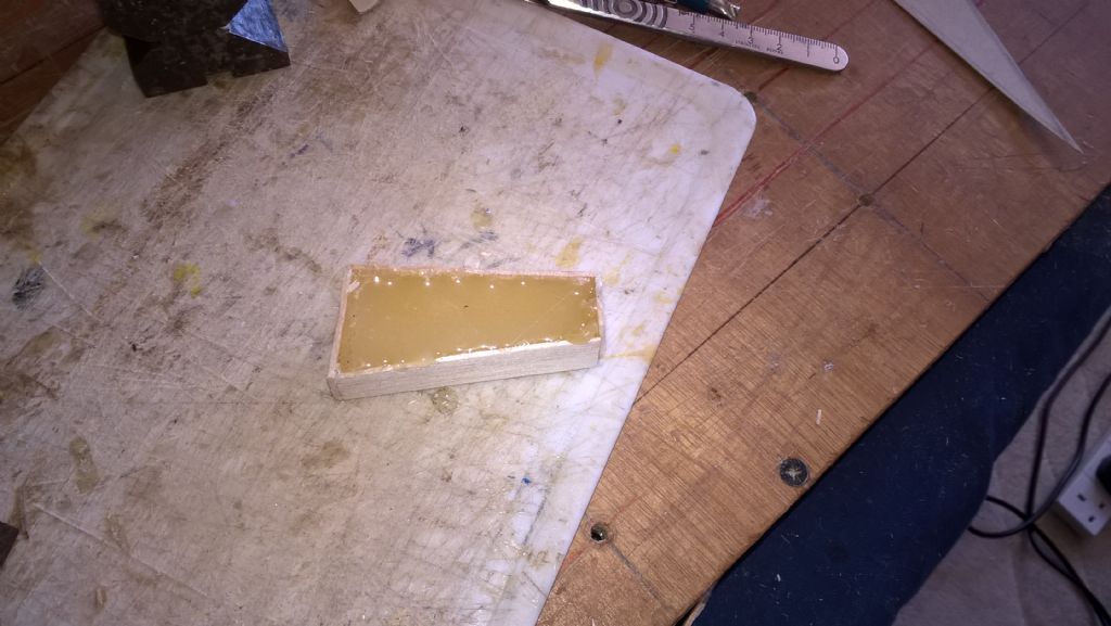
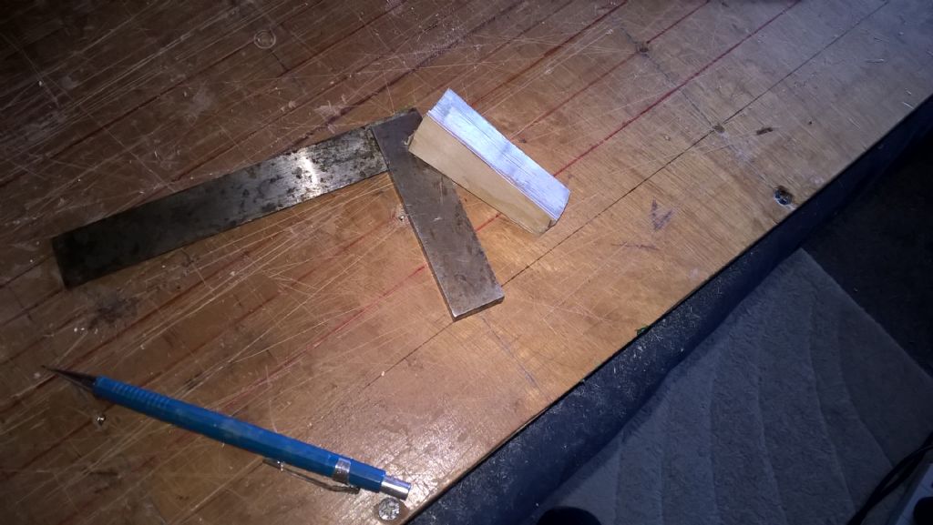
I have started on the bumber. I have used Glue Sticks as the material. The main problem is that it does not file well, being waxy. It has adhered well to the ply carrier.
cleaned up a little
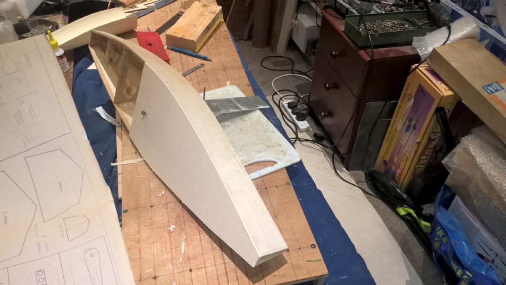
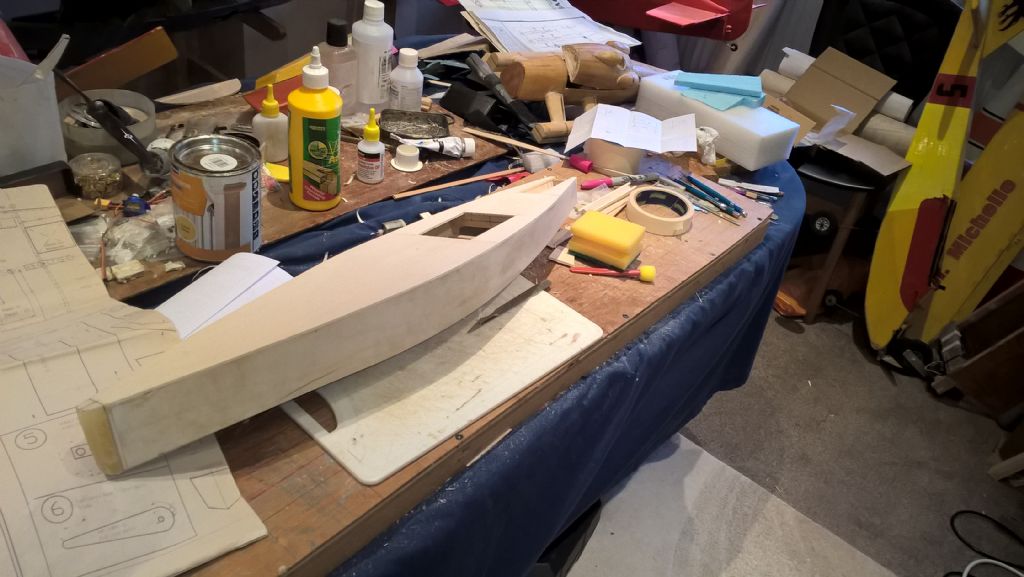
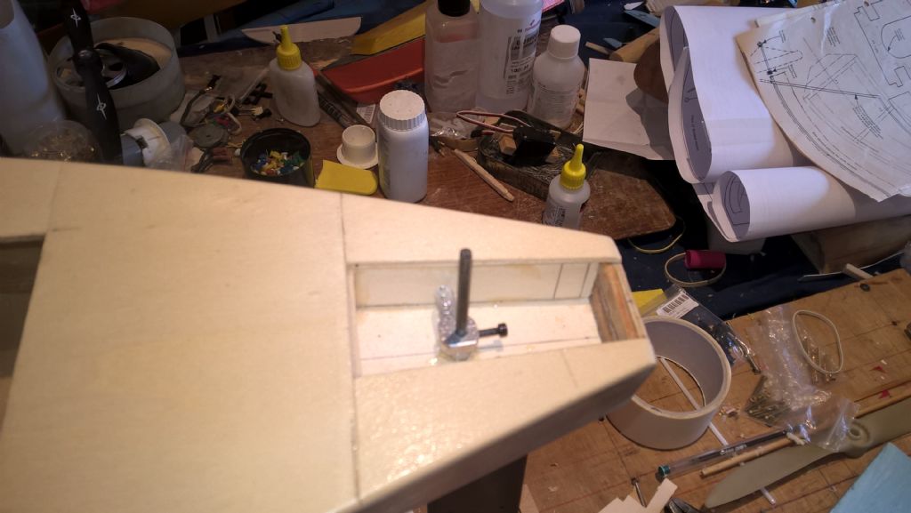
I decided to put on a fore deck, to keep the project moving.
I have ground to a halt as the back end design may be light weight, that other than the servo gross beams are heavier (bigger Size) material than I see on many modern model large scale aircraft, with +50 cc engines. On that basis I will be cutting the size down, may even use a Balsa ply fabrication. Although I keep reminding myself, my model will not race and its builder is not capable of sailing, not yet.
I notice that the model detail shows a arm to operate the sails (on the servo), rather than a drum. I can see the toque advantage and the linear benefit of a drum, although not sure that it really matters. My main concern is how the cord gets onto the deck and access to the rudder arm. Al lot to think about, as functionality and robustness is more important to me than weight, leading to a performance advantage.
11 April 2021 at 10:21 #94771Malcolm Frary
Participant@malcolmfrary95515Arm vs drum, there is considerable debate, and the answer is always what works for you.
Arms are on the face of it simpler, but this only applies if various factors are true.
The mounting must be strong enough to withstand the twisting forces without the servo moving in the mount or the mount twisting the hull.
The servo needs to generate the torque required to pull the sails in in the strongest wind anticipated (and on some days, a bit more)
The electrics need to be strong enough to supply the current that a powerful servo can try to draw. Good battery, good wiring.
Great care is needed laying out the running line. Travel is always at a premium with any arm system. Usually, the line coming to the arm is doubled back to a fixed point. Travel is doubled, torque to the line is halved, but the same twisting force is applied to the mount. It is a good idea to ensure that when "full out", the end of the arm is as near as possible to the entry and tie-off points of the line, and that when "full in", the line passes as close as possible to the servo arm screw.
Drums are generally not as fast as arms, but do offer the same pull throughout their range.
They are generally less greedy for amps.
A shrouded drum (and most of the servo size ones are) only needs to have the shroud leaning on the bulkhead that the line comes through and very little fixing. Any more is optional.
Travel is not usually a problem unless you need to actually lose some. My preference is a doubling arrangement above deck. This does slow things a bit but allows (with a suitable spread of the ends of the double) for greatly increased torque when it is needed, i.e. close hauling.
A drum does give the option of a single line, single ended system, or a continuous loop system.
Both systems benefit from having an elastic line helping take up any slack. Very essential on an open drum, single line, a good idea on a shrouded one, also on an arm. In light airs, where the sail relies on the wind to move the sail out, it might not keep pace with your command. The result is slack line. Unshrouded, the line falls off, shrouded, it can try to tangle inside the shroud, with an arm it will try to tie itself around anything available. From experience, the on/off switch is deeply annoying. The elastic line does, of course, give extra resistance to pulling in.
My boats that have a low after deck usually have the line exit via a tube that essentially slopes down to its exit point. A longish tube with a bit of slope slows water down enough and allows any that finds its way into the tube a way out when the boat isn't burying hat bit under water. The wet line, when pulled in, does bring some in with it, of course. For the rudder rod, I use a bellows. Idea borrowed from the power boat lads. A very similar item is used by cyclists on the brake end of their cables.
11 April 2021 at 12:12 #94772Dave Cooper 6
Participant@davecooper6Carl
I think it's fair to say that most (all ?) projects go through their 'up' and 'down' phases and may seem over-whelming in complexity at the time.
Sometimes, it is better to put it aside for a while and then come back to it. I'm currently designing and building a full-size Le-Mans style sportscar. Many, many, times I've had to take a step back and approach a problem from a different angle….
That's why I have something like my Pilot Cutter running in parallel for 'light' relief !
Coming back to your project, if you're not going racing, does it matter if everything isn't optimal ? The main aim is to have fun after all. I would say firstly get something working and then worry about how to improve it. The learning will come as you go along.
Best regards,
Dave
15 April 2021 at 18:16 #94859carl brotherton
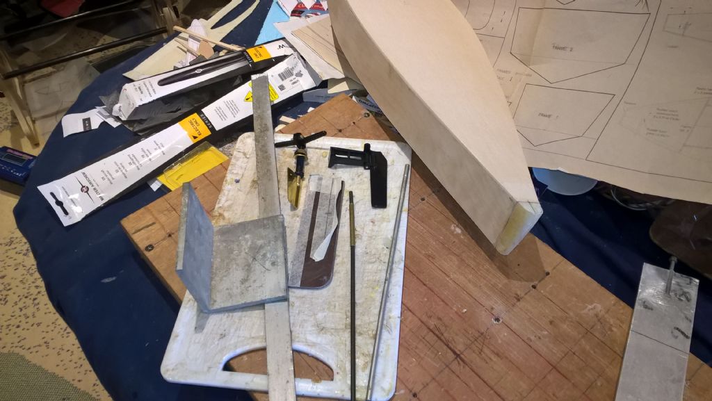
Participant@carlbrotherton75833There are very few details on the plan with respect to the rudder assembly. The outline of the rudder is provided, and that it should be made from 3/32" balsa.
Balsa seem not quite right to me, so I decided to us some Phenolic (Bakelite) sheet I have. The shaft size specified is 1.55mm diameter. Again seems a little light to me.
At present I intend to use something about 3.5mm diameter, and suitable brass tube. I do have similar lighter piano wire and brass tube.
The rudder arm is also a issue for me. I have two examples, which are very different, lever arm. At present I favour a shorter arm, on the basis, that rudder uses max throw when tacking. The rest of the time it is left inline with the fin. I could use exponential to reduce the movement around the inline setting, then further movement provides max. movement. All this is based on my guess, not knowledge.
The picture shows the materials I at present expect to use.
The bumper is the glue stick suggestion.
15 April 2021 at 21:06 #94866Malcolm Frary
Participant@malcolmfrary95515Bumper looking good – nice to see a thought exercise work out.
Tiller arms. I like to use a piece of brass that has been lovingly crafted with a convenient hole to poke the rudder shaft into, and a threaded hole, with a matching brass screw. Or a pin from a 13A plug, as it is known. Just needs a hole drilling at the right distance to accept the control rod. If using a Z bend, a bit of filing will thin it down easily to allow threading the rod.
Avoid at all costs dissimilar metals for rod and tube. Electrolytic welding is annoying to deal with a week or so after the first sail. Plastic tubes don't have the problem. Turning both shaft and tube in the hull against the glue holding it in place puts a considerable strain on the servo.
Training your right thumb and having a reliable parallelogram linkage layout is the conventional way to go. It's conventional because it works without the hassle of over thinking your way into problems.
If using wood for a rudder, laminating with the sheets having crossed grains works well. Also lets you choose whatever method you prefer to stop the shaft twizzing round inside the rudder. An L bend is totally effective, filing a couple of flats on the shaft and sitting the result in epoxy works as well. When balsa is laminated and coated, it is very much strong enough. BUT since it is the most exposed part of the entire project, my preference is to regard it as a mechanical fuse – I will break something that is easy and cheap to replace/repair rather than something difficult within the hull. I might mutter a bit about that, but for me it is better than the alternative.
16 April 2021 at 11:25 #94883carl brotherton
Participant@carlbrotherton75833I have now purchased a Dragonforce kit, it should arrive in the next few days.
The why, is a direct consequence of progress being increasingly hampered by a lack of knowledge.. Stepping in to areas of less knowledge of convention or operation.
Hmm Plastic bearing tube may be more of an issue, in that I have metal tubes, that match the piano wire. I will have to see if I have any thin walled plastic tube, that is suitable.
With respect to the rudder arm the dimensions will now be influenced by what the kit has.
I am not a enthusiastic metal worker. In the distant past, as part of so called practical training, this was all about workshop practice, including fitting, sheet metal work, electrical joint making, instrumentation manufacture, turning, machining, and forge work., welding techniques You know what, I disliked all of them. Much preferred academic studies.
My luck is that I have inherited a lot of tools from my father, and items picked up along the way.
On the basis above, Making the arm is not looked forward to. The real danger is that I stop building, until this aspect is completed.
Edited By carl brotherton on 16/04/2021 11:26:09
Edited By carl brotherton on 16/04/2021 11:29:17
16 April 2021 at 16:04 #94891Malcolm Frary
Participant@malcolmfrary95515If using 1.6mm stainless, the tube from the inside of a dead ball point pen refill is a sliding fit. It will need support, but a brass tube with a matching ID will do. The tubes from cotton buds were good, but they may now be environmentally banned. At my secondary school there was woodwork in the first form, art extended into the second form and that was that.
If using a vice and a drill to persuade a 3mm brass rod to fit in the thickness of the rudder, rubbing a bit of a brass plug pin will be as nothing. It does help to have a dremel or similar to drill the hole, though. Having said that, commercial tiller arms are cheap. ish.
If sailing in salt water, mixing and matching metals in contact with each other is a definite no-no, either in the water or just somewhere on the boat..
I've just spotted something in a flyer from Banggood – it seems that what I have been calling a bellows (for waterproofing round a rudder linkage rod exit) is called by them a "Waterproof plastic organ sleeve" or, rather wonderfully, a "water against accordion part".
Edited By Malcolm Frary on 16/04/2021 16:12:51
16 April 2021 at 19:48 #94896carl brotherton
Participant@carlbrotherton75833Malcolm, I use a pillar drill (these days often called a drill press). I do have a Dremel, with a chuck, which is most useful.
After many years on this planet, I do have a selection of power tools. Many targeted at model making. Some I was doubtful about their usefulness. Perhaps the best most recent purchase is disc sander from Aldi, my sanding is now much improved, although accuracy is not guaranteed, it is much easier to achieve and much faster.
Yet my biggest disappointment is a Dremel Jigsaw table, the now cheap Chinese imports are much better.
Perhaps I should mention that I am and have been a Aeromodeller for many years, in addition to making models as a child. Like many I spent a working life climbing the greasy pole, to provide a roof, food on the table, getting my kids educated, which I saw and still see as true success.
I remember a time when nearly every park had a model boating lake, now apparently long gone.
Edited By carl brotherton on 16/04/2021 19:49:53
19 April 2021 at 11:02 #94943carl brotherton
Participant@carlbrotherton75833I have received a kit of a Dragonforce 65 from "RC Yachts" this morning. A very timely service, just getting the purchase out of the shop, then the carrier was also pretty good, arriving in the time period both Emailed and telephone (land line, something that is never, ever used now, where did they get that from).
Well, just a quick scan of the kit, illustrates many aspects. The first is that much that I intended doing, is certainly different to at least kit this kit model. I thought I was building the equivalent of a recreational trekking horse, rather than a race horse. I now find that at my model is more akin to a Heavy Horse. Everything is robust.
Will the decisions from now on produce a hybrid that are neither "one thing or the other".?
I am now considering that lighter weight rigging if inadequate to my incompetence can be replaced with something a little heavier. Although not the 5mm Deema twine that I was seeing as necessary to deal with the massive forces from the sails, that I envisaged.
Edited By carl brotherton on 19/04/2021 11:05:13
19 April 2021 at 16:10 #94947Steven S. 1
Participant@stevens-1Hi Carl – I do hope that you will carry on with your JIF65 build as I am planning on building one also and have downloaded the plans and a 26 page building manual from AeroFred, a free plans service that I have used for several of my airplane builds. The only problem is that all the verbiage is in Spanish [I think]. The manual should help as it has lots of illustrations for the complete build.
I, along with several club mates have also bought DragonForce 65’s to learn how to sail this summer. Luckily we have one in our group who has been sailing RC boats for a few years and is looking forward to teaching us so that he has some company sailing. Assembling the DF65 is pretty straight forward and I have put a couple of rigging diagrams and pictures into my DF65 album on this site. They cleared up a few things for me.
I’ve been building planes since I retired a few years ago, but flying conditions have been poor around here what with high winds and other poor weather conditions so I started making boats since the Covid shutdown here in Canada last year. I’m just finishing my drogher build and then want to build the JIF next and since my only sailboat experience so far is assembling the DragonForce I will probably buy a complete A rig and keel bulb from them for my JIF build.
21 May 2021 at 20:24 #95662carl brotherton
Participant@carlbrotherton7583328 May 2021 at 18:43 #95794carl brotherton
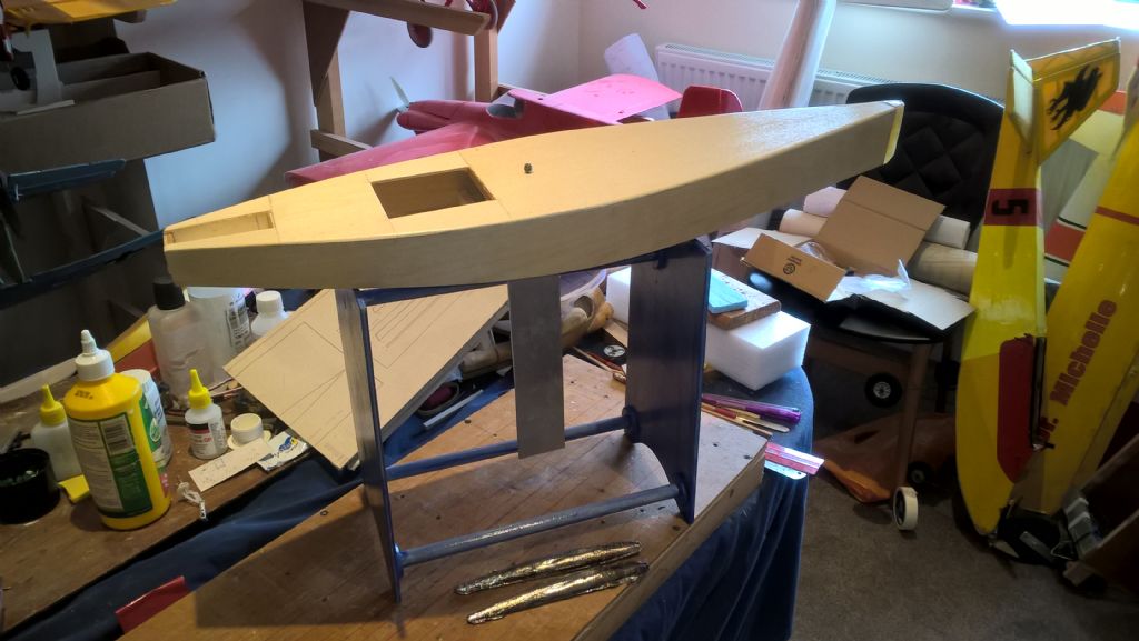
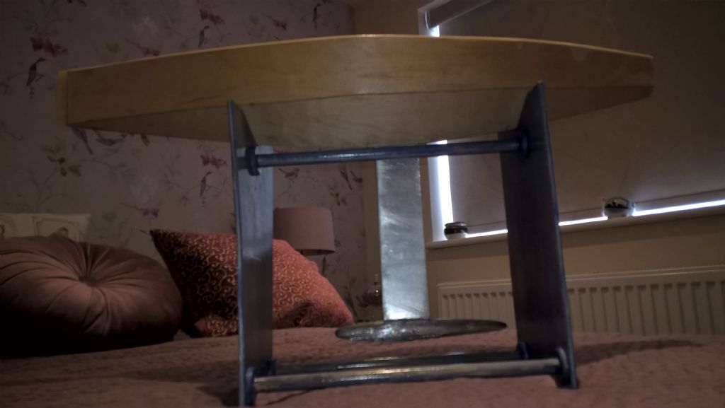
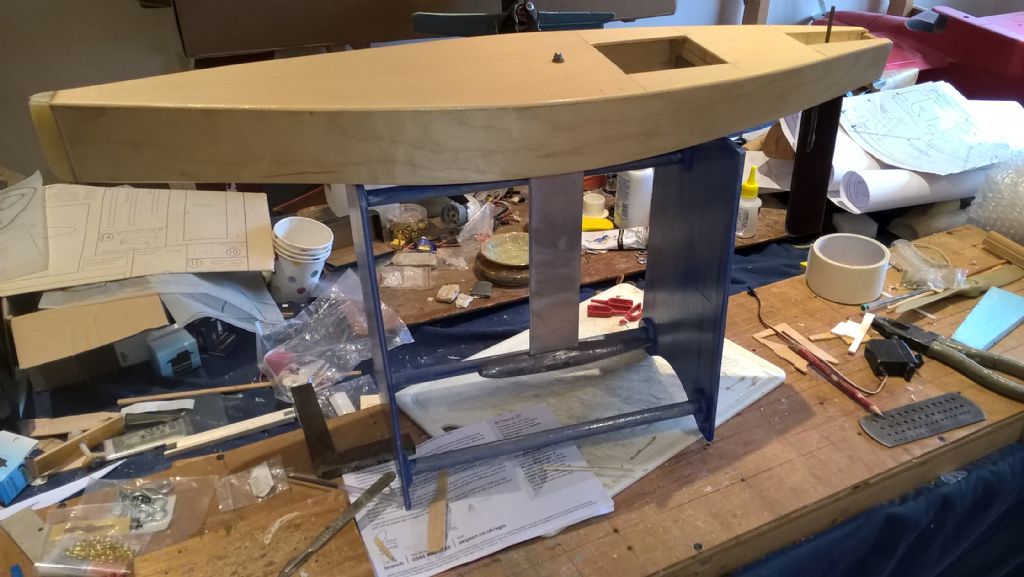
Participant@carlbrotherton75833I decided that a must do, or have was a stand, as supplied with the Dragon Force.
I drew inspiration from the Dragon Force stand.
I could have left it a s varnished ply and pine, though this would look so 1960s. So it is a blue lcolour wash then varnished.
I have cast the lead bulb, now. I need to clean it up. At present it is approx. 100g over weight. The question is does it matter being over the plan weight, or the other option under weight?
Edited By carl brotherton on 28/05/2021 18:44:07
28 May 2021 at 20:24 #95798Tim Rowe
Participant@timrowe83142Hello Carl
By the time you clean it up and drill a couple of fixing holes you won't be far off. You are not going to be breaking any rules so lead left on the keel will be more use than lead filings on the floor!
What is the weight incidentally?
Tim R
28 May 2021 at 22:47 #95803Steven S. 1
Participant@stevens-1Hi Carl – glad to see that you are back into the JIF build. I'll be following as making a JIF65 is on my to-do list.
2 June 2021 at 11:54 #95894carl brotherton
Participant@carlbrotherton75833The plan quoted weight is approx 460 grams.
Hopefully I will be back on the bulb tomorrow.
I (should) have some thin flashing which I (when found) intend using as a spacer to the keel thickness. At present my intension is to use epoxy to join the two halves together. That is in addition to some 2BA bolts. How does this fit with current practices?
I will then round the leading edge of the fin. At present my intension is to leave the trailing edge cut at 90 degrees to the face. This is on the basis that very little is to be gained by a short taper, and a long taper takes a lot of effort to achieve if any real benefit is to be gained.
3 June 2021 at 09:33 #95908Malcolm Frary
Participant@malcolmfrary95515A square edge at a transom works very well because once the hull is going fast enough the grip of the water is broken. Normally, this only applies to powered hulls. Underwater, a different story. Air is not replacing the turbulent water at the back edge of the fin, but water is being pulled into what would otherwise be a void. Creating turbulence like this takes energy, and appears as drag.
Commercial racing fins are sharp enough on larger models (e.g. IOMs) to make use of gardening gloves advisable when carrying the boat. My home made efforts in ply usually have a small radius, either because I sanded them that way, or because in one case I took it to an edge and carrying it over time wore it to a radius. Edge vs radius showed no noticeable difference for cruising, so a bit of effort (say 5 minutes with a power sander) creating the taper, will pay dividends when you want to steer the boat later.
The bulb plot is sound. The entire bulb will presumably get a layer of epoxy or similar to ensure that it has a watertight skin so that the bolts never get wet. Even so, investing in stainless or brass bolts might be a good idea.
Edited By Malcolm Frary on 03/06/2021 09:38:43
19 June 2021 at 12:46 #96237carl brotherton
Participant@carlbrotherton75833It appears that la little progress has been made. For me a lot of unanticipated work has been involved, that took time.
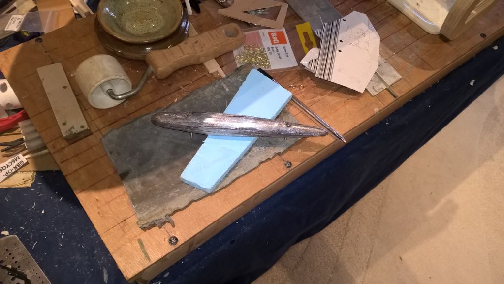
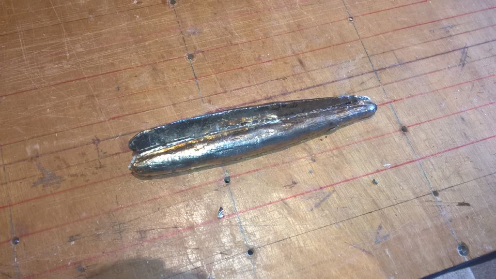
this was the basic cleanup, pretty quick, other than no means to fasten the keel was made. At this stage some 70-100g overweight, target 460g.
the picture is a little dark(obvious when viewing). The bulb is held together using 4 off 6BA screws and nuts, together with epoxy resin. I did try to tap the Lead. but proving far to soft and ductile to be useful. By this stage it was just a shade over 460g.
I am a little concerned about the lead being very soft and malleable, ductile, to resist denting or other damage. How are Lead bulbs normally finished?
19 June 2021 at 15:41 #96241 Ray Wood 3Participant@raywood3
Hi Carl,
Your lead will be fine just painted, but if you feel compelled I would fair it into the fin with some P38 body filler and fill an imperfections in the lead, rub down & prime, I use Halfords Red Oxide primer then Satin Black spray paint

Regards Ray
24 June 2021 at 16:32 #96374carl brotherton
Participant@carlbrotherton75833Still plodding along. I thought I had most of the work done on the hull, when I realised there was no rudder etc. So that has been what I have done. Again, compared to the plan My own attempts belong to the battleship end of construction. I just could not believe that 1/16" balsa was viable, or even 1/8". My version uses phenolic sheet as the basis. The shaft bearing length is also longer, the shaft is drawn rod, running in a plastic bearing, that has been epoxied into the hull (fully supported.
I still have to fashion a drainage hole from the well.
My thoughts are turning to servos, I will use a drum drive as the arm alternative causes the thread to move through a linear quadrant or arc (whatever), with variable torque to the rudder arm. I can now see that the drum has the thread moving along a constant path, the torque applied is consistent and finally I can keep the hole through which it passes quite small. Still do not know what brands are wort considering, or how powerful a servo is needed for the rudder.
It is my intention to replicate pretty much the Dragon force rigging. Although I do not know if the JIF plan indications for the running eyes are consistent with what will be needed.
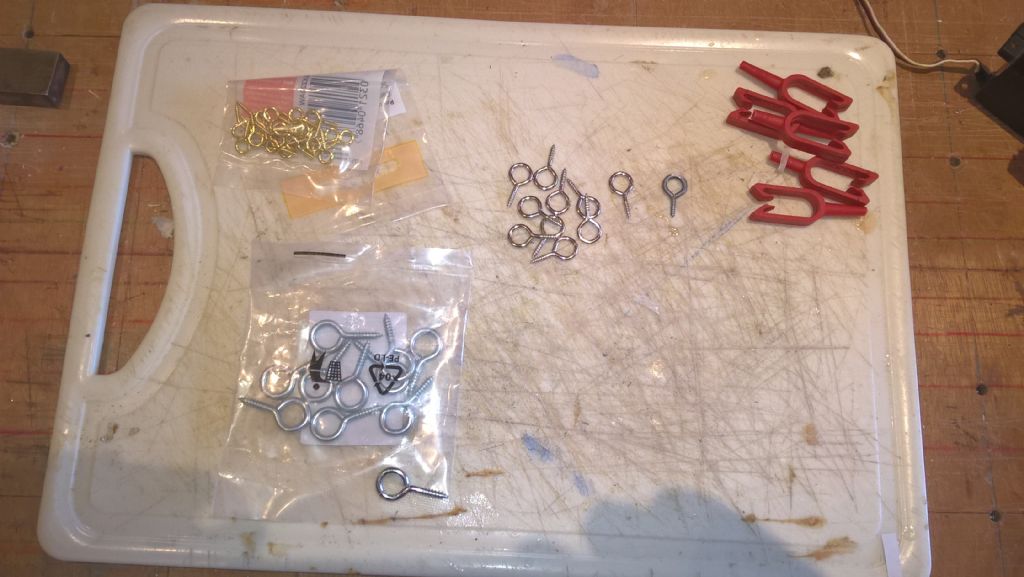
Nor do I really know which eyelets to use.I now have a selection.
Given that the boating lake near here is saltwater, I am not at all sure that Brass is the best, nor is the steel, chrome plated any better. I would use Stainless steel, also knowing that this is prone to Chloride attack. I guess that a good wash down is needed for all the options.
I am about to make the plate for stepping the mast. The JiF drawing calls or 1/16" thick material. I am tempted to go with 1/8" or thicker aluminum plate. The aim is to provide a improved location fro the stepped mast, I just do not know! What is the experience out there?
25 June 2021 at 10:07 #96400Malcolm Frary
Participant@malcolmfrary95515My thoughts are turning to servos, I will use a drum drive as the arm alternative causes the thread to move through a linear quadrant or arc (whatever), with variable torque to the rudder arm. I can now see that the drum has the thread moving along a constant path, the torque applied is consistent and finally I can keep the hole through which it passes quite small. Still do not know what brands are wort considering, or how powerful a servo is needed for the rudder.
Do some measuring. Determine the distance from the boom connection point to the deck connection point both when fully "in" and "out". The difference is the needed travel. The drum is approx 1" diameter, 3 and a bit inches per turn. A 2 turn winch will do the job, DF65 uses , I believe, a 1.5 turn winch. A bit of extra travel lets you be a bit sloppier in line layout. I prefer winches for their simplicity in installation in a confined space, but an arc, properly arranged and with a sufficiently high torque servo, uses the variable torque to advantage. Probably the King Max 2 turn metal geared one.
For the rudder link, swinging the rod through an arc is no problem – just make the hole oval. The speed lads use rubber bellows to cover the hole. Simple, cheap, works. Rudder servo? Look in the DF65, observe the mini servo, get a similar one with metal gears.
Given that the boating lake near here is saltwater, I am not at all sure that Brass is the best, nor is the steel, chrome plated any better. I would use Stainless steel, also knowing that this is prone to Chloride attack. I guess that a good wash down is needed for all the options.
Brass. As simple as that. Stainless steel if that is needed for strength. Chrome plated steel is a disaster in a hurry to happen, chromed brass or stainless, OK. Lacquer is good.
None of my boats have ever used a deck plate for the mast. Wherever possible, they are keel stepped and sit in a brass tube that goes from deck to keel (meaning hull bottom in this case, not the lump on the end of the fin) and is an integral part of the rigidity of the whole thing under load, avoiding putting any undue stress on the hull structure.
A bit of extra weight in the rudder will probably be offset by the weight of water that it displaces, but a lightweight rudder "might" provide a bit of buoyancy at the stern, which might be a factor in the performance of the original. Having a rudder that is not quite as strong as its mount is no bad thing. Careful handling is no bad thing, but a broken rudder is much easier to fix than a broken hull.
Edited By Malcolm Frary on 25/06/2021 10:10:22
1 July 2021 at 16:06 #96592carl brotherton
Participant@carlbrotherton75833Malcolm
Somehow I missed the notification of your post.
In the mean time I ordered a 1.5 turn drum servo. The why. In the absence of a a reply
 , I decided to follow the Dragonforce installation.
In the mean time I have stumbled on quite a bit on the JIF. I was particularly interested the rigging. Although it became apparent how to build the hull as just skins, butted. You build a beam which attach the bulkheads and a outline female deck plan. It seems as easy in my opinion to have stringers at the chine points, the increase in weight, may be more theoretical than real.
The detail of the mast fittings, have me wondering, is this good practice, may save a gram or two at best, perhaps at the expense of robustness. But then again, I really know very little with no experience at the practical end of building and particularly operating.
So for the moment I am focussed on the servo installation. Although tempted to start on the mast.
I have a drawing of the JIF sail and a template of the Dragonforce, against which I will compare the two. Ni idea what I might draw from the process, but seems worth while.
2 July 2021 at 09:47 #96605Malcolm Frary
Participant@malcolmfrary95515Almost everything on a model has more than one job, especially the rigging. The primary job of most of it is to stop the mast falling over.
The backstay stops it falling forward in a following wind, but also, when correctly tensioned, affects the shape of the mast and the sails attached to it.
The side stays, if used, keep it upright in a side wind and help keep the mast rigid. Also very useful when launching and retrieving as you can lift the boat by the mast, letting it dangle easily (holding by the mast like it was a frying pan is not recommended). With a deck stepped mast, they also transmit all of the forces from the sails through the hull on their way to the fin, which is shoving the other way.
Some boats have a fore stay, which stops the mast falling backwards. Many (racing types where there isn't room for a forestay) use the fore sail and its associated lines to do the job. There is a line running down the leading edge of the sail (which is tensioned to this support line) to the front end of the boom, the boom itself, and a swivel or bit of line from a point on the boom to the deck. Some get a leech line, which starts somewhere near the top of the sail and goes to the rear end of the boom. This completes the triangle and allows the fore sail to be properly shaped without being unduly tensioned.
My version of keel stepping doesn't allow for adjustment, if I need to alter things to get a better balance, I need to do something radicle with sails. A deck plate allows for adjustment.
A gram saved at the upper end of the mast is ounce saved down below, since the weight down at the bottom doesn't have to counterbalance as much weight at the top to provide the righting moment. Since both DF65 and JIF are intended to conform to the same racing rules, there will not be huge differences between the two sets of sails, and, being of very similar area, will generate very similar forces. Of course, cut, shape and material will make differences, as will their eventual fitting and adjustment.
2 July 2021 at 20:08 #96616carl brotherton
Participant@carlbrotherton75833Thank you yet again Malcolm.
The discussion with respect to the functionality and other ideas, that really do help with respect to understanding.
Although the Dragonforce has supposable a stepped mast, it actually sits in a pocket of about 20 or so millimeters. I would call this a half way house solution. Most probably driven by the moulded hull.
At the moment I intended to use the 6mm aluminum drawn bar (extruded?) as the locator. I must admit I am a little surprised at the spacing of the alternative positions, on the basis , that is quite a range of mast positions. I think, what is the advantage, under what circumstance, would i have a clue as to when and why?
I am now just thinking and planing my servo mounting plate, with the battery position. I ma leaning towards a 2 or 3 s Lipo, as i have noted a number of model glider modelers are using such a set up without a voltage regulator. It all depends on what the Rx and servos (I have ) will tolerate or use a UBEC to deal with the voltage.
3 July 2021 at 09:19 #96627Malcolm Frary
Participant@malcolmfrary95515If you go the LiPo route, no more than 2S. That is the maximum that easily (and cheaply) available servos can handle, and even that would probably be better (safer, longer lasting) fitted with a UBEC to bring the voltage to something that is universally accepted. Regulating down from a higher figure just means that you are carrying more battery than is needed with no real benefit. While UBECs are efficient, they are not THAT efficient.
From my days of collecting and reading data sheets for ICs, 7.5 volts was a common figure for the maximum voltage on chips used in the modelling world. Anybody running such chips above that was relying on a combination of dumb luck, and, in the case of flyboys, lots or air flow providing cooling. A freshly charged LiPo can exceed 8.4 volts – I have seen some that claim 8.4 on the label.
-
AuthorPosts
- Please log in to reply to this topic. Registering is free and easy using the links on the menu at the top of this page.
Code of conduct | Forum Help/FAQs
Latest Replies
-
- Topic
- Voices
- Posts
- Last Post
-
-
Fairey Huntsman 28
1
2
…
7
8
Started by:
 Chris Fellows
in: Build Blogs
- 2
- 197
-
12 hours, 33 minutes ago
 Colin Bishop
-
Vic Smeed’s Silver Mist
1
2
…
33
34
Started by:
Bob Abell 2 in: Scratch build
- 5
- 828
-
15 hours, 53 minutes ago
Tim Cooper
-
Building a hull.
Started by:
 mick east
in: Scratch build
- 7
- 16
-
1 day, 20 hours ago
 mick east
-
Fairey Faun
1
2
3
Started by:
 Chris Fellows
in: Build Blogs
- 7
- 60
-
2 days, 13 hours ago
 Ray Wood 3
-
superglue allergy
Started by:
 Alasdair Allan
in: All things floating
- 5
- 12
-
3 days, 13 hours ago
Tim Cooper
-
Model Yacht Racing – The future ??
Started by:
 Ray Wood 3
in: Sailing Models
- 4
- 4
-
4 days, 7 hours ago
 Richard Simpson
-
Vic Smeed’s Legacy
Started by:
 Colin Bishop
in: All things floating
- 6
- 15
-
4 days, 11 hours ago
 Colin Bishop
-
Eezebilt RAF Fire Boat
Started by:
Tim Cooper in: Build Blogs
- 4
- 9
-
4 days, 12 hours ago
 Colin Bishop
-
Feathered Friends
Started by:
 Chris Fellows
in: Soapbox
- 3
- 9
-
5 days, 7 hours ago
 Richard Simpson
-
4D Modelshop
Started by:
Keith Long in: Scratch build
- 6
- 9
-
6 days, 14 hours ago
 Colin Bishop
-
Fairey Huntsman 31
1
2
…
5
6
Started by:
 Chris Fellows
in: Build Blogs
- 14
- 139
-
1 week ago
 Chris Fellows
-
John Cobb’s Crusader
1
2
…
7
8
Started by:
 Paul T
in: Scratch build
- 1
- 192
-
1 week, 1 day ago
 John W E
-
Complex Automata
Started by:
 Colin Bishop
in: Soapbox
- 1
- 1
-
1 week, 2 days ago
 Colin Bishop
-
RAF Fireboat ID
Started by:
 Dave Reed
in: Collectors’ corner
- 8
- 24
-
1 week, 3 days ago
Tim Cooper
-
TID steam tug 42″ – PN Thomas drawing enlarged
1
2
Started by:
 Ray Wood 3
in: Scratch build
- 8
- 33
-
1 week, 4 days ago
 Richard Simpson
-
Lady of Skye (puffer)
1
2
Started by:
 mick east
in: Build Blogs
- 9
- 43
-
1 week, 4 days ago
 Richard Simpson
-
Todays Boating
1
2
…
210
211
Started by:
 ashley needham
in: All things floating
- 84
- 5,252
-
2 weeks ago
 Colin Bishop
-
Sea Rover Restoration
Started by:
harry smith 1 in: Collectors’ corner
- 4
- 10
-
2 weeks ago
 Richard Simpson
-
WORKSHOP LIGHTING
Started by:
 John W E
in: All things floating
- 9
- 18
-
2 weeks, 1 day ago
 Colin Bishop
-
Mayhem Website Down
Started by:
 Colin Bishop
in: All things floating
- 4
- 10
-
2 weeks, 4 days ago
 Colin Bishop
-
MAGGIE M trawler
Started by:
 sammyk
in: Buy/Sell or Trade
- 2
- 3
-
2 weeks, 4 days ago
 sammyk
-
meter
Started by:
 Alasdair Allan
in: All things floating
- 5
- 16
-
2 weeks, 6 days ago
 Chris Fellows
-
River Queen 2”- 1’.
Started by:
Richard B in: Steam powered models
- 5
- 7
-
3 weeks ago
Richard B
-
Deluxe Superphatic Glue.
Started by:
 Colin Bishop
in: All things floating
- 4
- 12
-
3 weeks ago
 Chris Fellows
-
How to add photos to your posts
Started by:
 Colin Bishop
in: Adding Images to Forum Posts
- 3
- 16
-
3 weeks ago
Len Morris 2
-
Fairey Huntsman 28
1
2
…
7
8
-


