JIF 65

Advert

JIF 65

Home Forums Beginners JIF 65

  • This topic is empty.
Viewing 25 posts - 26 through 50 (of 87 total)
  • Author
    Posts
  • #94118
    carl brotherton
    Participant
      @carlbrotherton75833

      I have. e to be honest and recognise that I know little to nothing about either design or operation (sailing) model yachts. Yet my logic suggests that there is a relationship between the keel position and area etc.

      Why is the obvious question. If it does not matter where the fin is (etc), then if I were push things to the extreme and place the fin at the bow, or at the stern. My other extreme vision is that the fin is minimised to essentially a rod to hold the lead ballast. I may be wrong, we do not see any of my propositions. It could simply be that approx. the middle of the boat is a convenient location.

      Because I do not know, I will follow the plan, slavishly (if that is not politically incorrect).

      It is also an explanation why I keep asking questions, then trying to understand "the why" and will need to continue to do so, as long as you can stand my ignorance.

      I even struggle to decided when to do the various bits, to establish and maintain the critical path.

      Advert
      #94121
      Malcolm Frary
      Participant
        @malcolmfrary95515

        A bit of "why".*

        Balance is everything in a windy boat. The forces acting on the sails apply force towards the front and back depending on the relative areas, and where they are. Too much at the front, the centre of effort being the average of the sails, the boat goes downwind, too much at the back, it points into the wind like a weather cock, and sits there. Or goes backwards.

        The boat tries to move in the direction that the difference in air pressure on the faces of the sails determines. Downwind, obvious. The sails just block the wind.

        Across the wind, the sails are angled to cause airflow across themselves, which, if they have the right curve, causes a difference in air speed and therefore pressure between the two sides, and puts a force into the rig. Left to itself, the boat will go sideways, but having a shape underwater resisting the sideways motion, the boat goes forward. Just how much of the sideways force is translated into forward and not left to sideways motion (leeway) depends on how the boat is set up and whoever is driving.

        Heading into wind, trigonometry says that up to a point, you still get the resulting forward motion, and you do. After getting to that point, typically 45 degrees off the wind, you get steadily less forward motion until the boat stalls.

        Finless boats tend to be better at straight running and are reluctant to turn which makes tacking one across the wind a bit of an art. Boats with fins usually turn easily, and as long as they have got enough inertia, can get through the dead bit between not getting forward drive and having their sails presenting their other faces to the wind before coming to a stop.

        Since every action has its corresponding reaction, the wind on the sails needs something the react to. This is provided by the hull in the water. This resists the sideways push. On a deep hulled boat with no fin but a long lengthways keel, the centre of this action is where it is according to the side area. On a shallow hulled boat with a long fin, the fin is the main component in deciding where the CLR is, and its position becomes critical.

        *Probably true enough.

        #94127
        carl brotherton
        Participant
          @carlbrotherton75833

          Being Sad, I went to sleep thinking, hmm, going down wind there is definitely no airfoil.

          Just as you say, a bit of Newtons physics, of action and reaction (is that Law 3 and all the rest 1,2 &3 at work).

          I am now thinking that is why the mast can be moved, backwards and forwards (if you know what you are doing) to get that handling balance.

          #94136
          Malcolm Frary
          Participant
            @malcolmfrary95515
            Posted by carl brotherton on 09/03/2021 17:09:05:

            Being Sad, I went to sleep thinking, hmm, going down wind there is definitely no airfoil.

            Just as you say, a bit of Newtons physics, of action and reaction (is that Law 3 and all the rest 1,2 &3 at work).

            I am now thinking that is why the mast can be moved, backwards and forwards (if you know what you are doing) to get that handling balance.

            Newton, Bernoulli, and probably a bunch of guys in ancient Egypt who had figured out sailing upwind with fore and aft rigs while our locals were still figuring out that keeping your thumb out of the way while banging rocks together was a good idea.

            #94144
            carl brotherton
            Participant
              @carlbrotherton75833

              I seem to be increasingly sad.

              As I drifted of to sleep, I was busy rearranging my preconceived thoughts on sails. Somewhere along the line I was told, perhaps read, that sails were an aerofoil. Beyond accepting that the idea was true, I still accept the idea.

              My problem was I thought of the arrangement just like an aircraft wing, the air(fluid) was essentially from the front. I accept that in many instances this is broadly true.

              My revelation (to me) was that often the model can be sailing down wind, with the boat at an angle to the wind. Under these circumstances the air, is striking/flowing around the sail from the opposite direction. That was a surprise to me, dumb or what.

              I then started to think how the sail is arranged to work effectively in both circumstances.

              I am now starting to think about how to cast and mount the ballast.. At present I am thinking that splitting the bulb vertically. Filling a recess on both halves, then bolting together and also onto the the Keel. On the other hand I could split the casting horizontally, with a slot cast in, as part of the mould. This seems more difficult, for a number of reasons. What is the conventional method?

              #94146
              Ray Wood 3
              Participant
                @raywood3

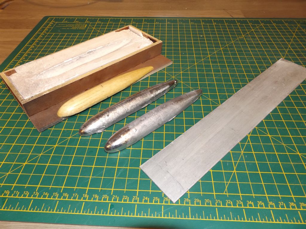
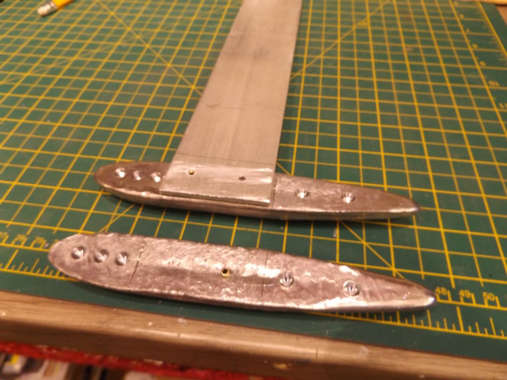
                eventide keel mould.jpgeventide fin bulb 2lbs.jpgHi Carl,

                To cheer you up and help you sleep soundly here is my method of producing a fin keel of 1/8" aluminium and two halves of lead cast in a plaster of paris mould taken from a balsa plug.

                Casting the lead involves a blowlamp, baked beans tin, mole grips and scrap lead 2 lbs.

                The lead bulb halves are cross drilled and brass pinned to the fin and epoxied and the gap filled with P38 body filler and sanded to shape.

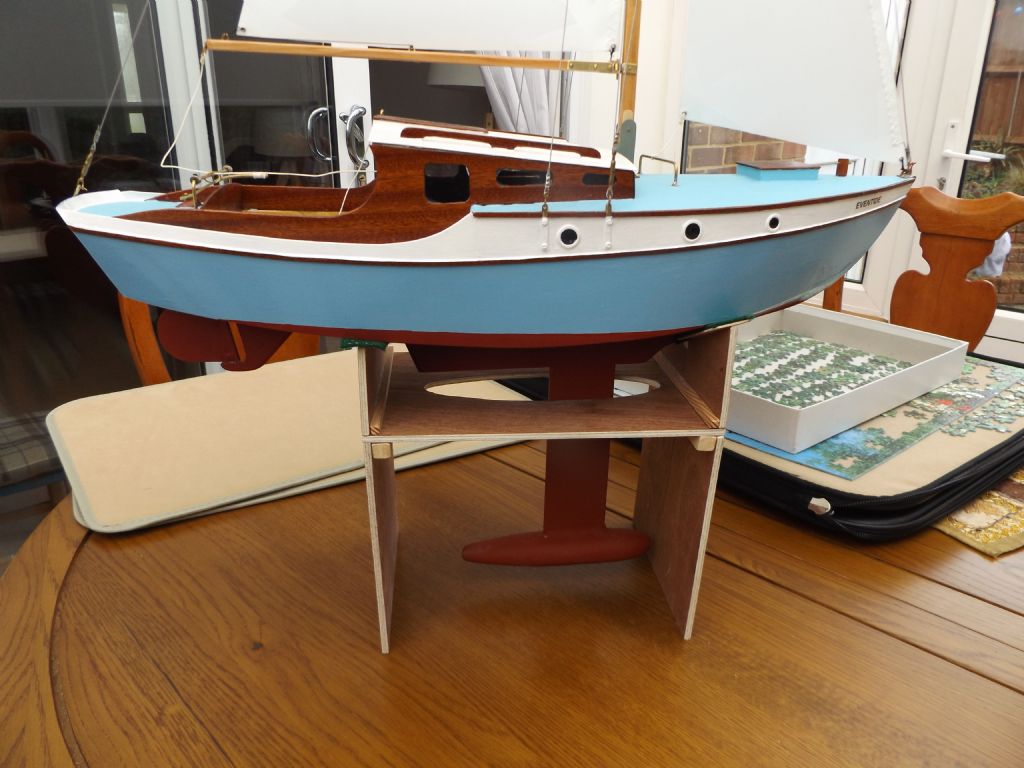
                This is the keel for my Eventide sloop which is around the same length as a RG65. but much prettier !

                Hope that helps

                Regards Rayeventide on ext stand.jpg

                #94147
                carl brotherton
                Participant
                  @carlbrotherton75833

                  Useful information Ray.

                  It is surprising how little you know when venturing into a new area. Thankssmiley

                  #94260
                  carl brotherton
                  Participant
                    @carlbrotherton75833

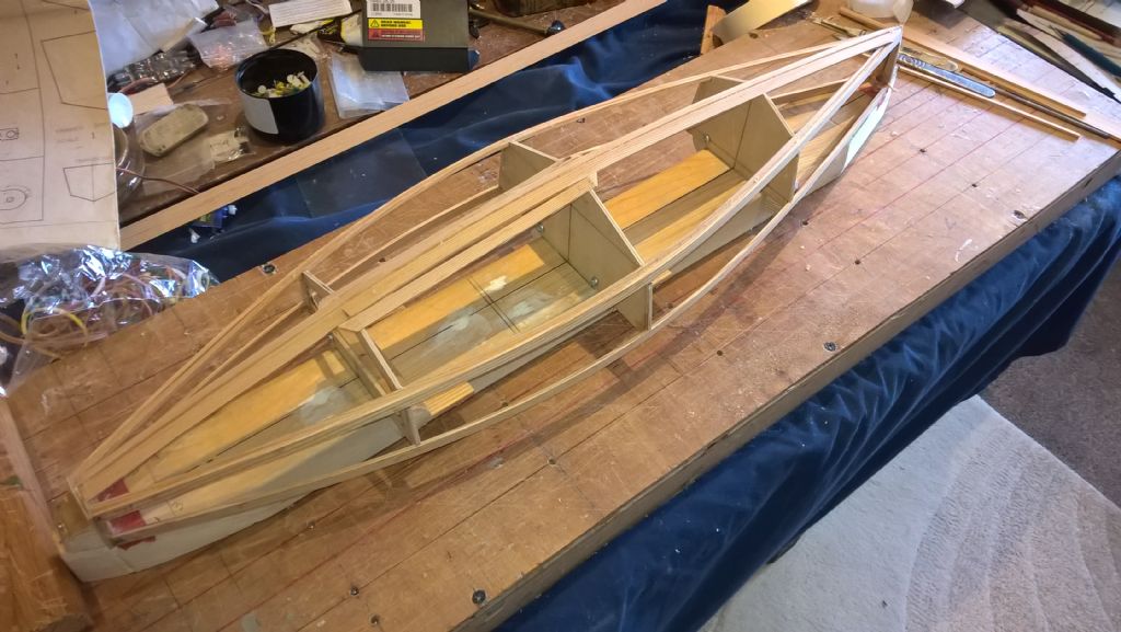
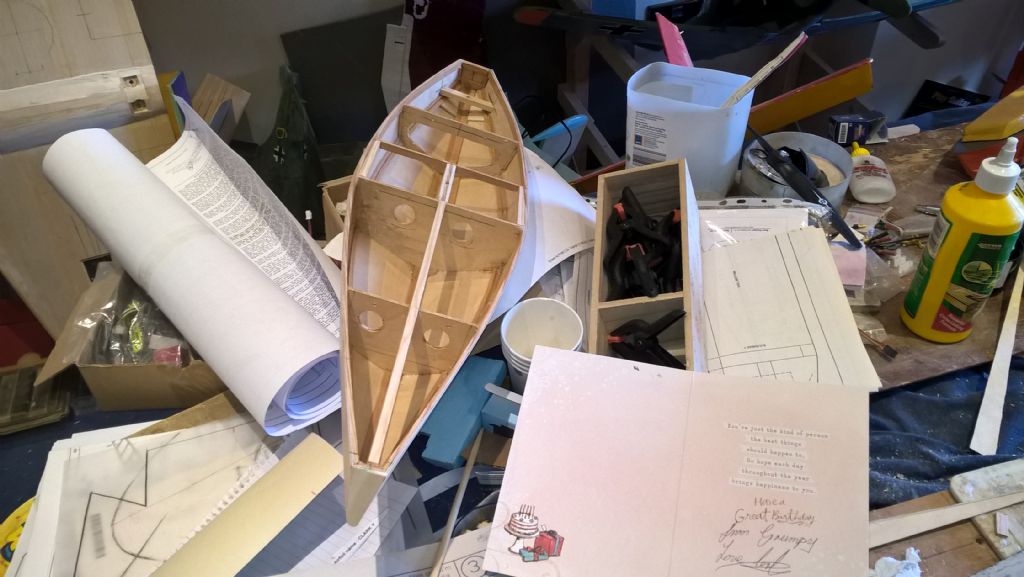
                    I have made some progress.although not as happy as I would have liked. My building is not up to the quality, I had hoped to achieve .

                    wp_20210315_14_18_32_pro.jpg

                    Constantly taken by various surprises.

                    The present issue that the keel re-enforcement has not taken the curvature I had expected. Eh, it was a no brainer that without some effort they would remain straight. I have decided that they are better left straight, subsequently I will put in some fillets to join the bits together, with a view to effective stress distribution, without building in any additional. I did consider soaking and bending to curvature, came to the conclusion, lets just keep things simple.

                    I have a few more things to do before ply sheaving.

                    I have noticed that one contributors picture shows the two sides of the hull bottom being done first. My instincts were to do the sides, so I could use pegs to clamp to the rails. This begs the question, what is the best way, what conventions have become established and why?

                    #94261
                    Ray Wood 3
                    Participant
                      @raywood3

                      Hi Carl,

                      As they say Rome wasn't built in a day

                      The strip you have either of your central keel strip are not serving any purpose, I would take them off. The topsides are easier to sheet first using a card or tracing paper template, I you are following my Chez When build you will see the bulkheads have extensions to the building board this raises the hull to give working space for clamps, the sides are easier than the bottom skins which you maybe able to pin in position while the glue sets. As the ply skins on the original are glued to the bulkheads you will need to use your stringer material to build out the bulkheads to have a gluing surface to get the strength.

                      I'm rather concerned about how you intend to release the hull from the cross members on your building jig as once sheeted as you have screwed the bulkheads to them ?

                      Sorry to be a know it all ! but I may have built 25 boats this way in the last 40 years

                      Best of luck Regards Ray

                      Edited By Ray Wood 2 on 15/03/2021 15:30:11

                      #94262
                      carl brotherton
                      Participant
                        @carlbrotherton75833

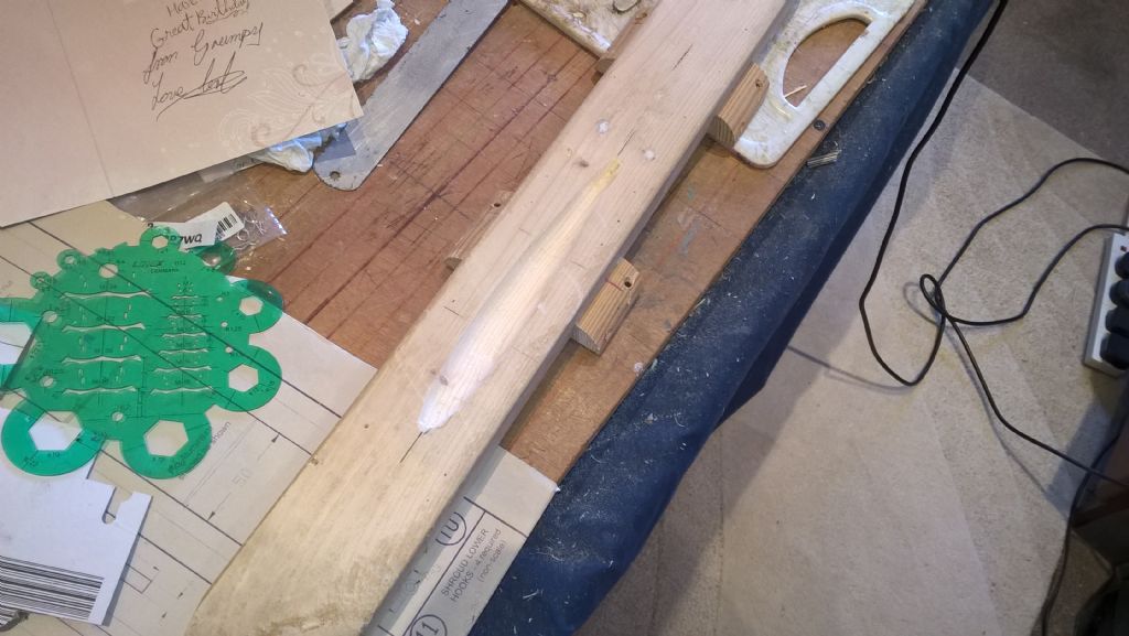
                        Ray, the bow and stern bulkheads are held by a single(very small) screw. The three central bulkheads are attached to the cross pieces again by small screws, inturn the cross pieces are screwed onto the sides of the chunk of wood. Removing the hull from the board by removing end and side screws allows the cross pieces to be unscrewed.

                        In the case of the central pine strip is primarily there to help in forming the curve of the bottom skins. When the keel box is inserted/formed, most of the material to the side of the pine will be removed. Then the two small side rails are there to provide a stress distribution in the area, rather than just the skins.

                        I expect to start on the skinning process at the end of the week.

                        With respect to surplus weight, I am less concerned about an excess, more about stress distribution, due to incompetent handling both on the water and even getting there whilst building and transport. In my case, the boat will have a hard life, as i cannot sail, nor handle the model (when completed) with any competence.

                        The comments are welcomed, as they help me form an understanding of what I am trying to achieve and the experience from others.

                        Edited By carl brotherton on 15/03/2021 17:12:48

                        #94287
                        carl brotherton
                        Participant
                          @carlbrotherton75833

                          Again looking for the conventional methods, ways, of covering, a vee hull.

                          I have now sanded the edge of the pine strips, as in one plane I left an edge slightly proud, so that the edge could be sanded back to conform to the bulkhead shapes.

                          I have now produced a cardboard template of the bottom of the hull. I thought that the sides template are best produced after the bottom has been attached.

                          Now I finally come to my uncertainties. The line around the keel has been produced what appears to be a good accuracy, on the template. I am proposing that I leave something about 1/8" excess on the stringer line. With this amount of excess, I anticipate that I can get the keel line, "bang on", by sanding. Then the excess at the stringer line can be sanded back to the stringer line, after the glue dries.

                          The question is 1/8" enough, is it even the appropriate methodology, for the task?

                          #94304
                          carl brotherton
                          Participant
                            @carlbrotherton75833

                            I am far from sure that the way i am doing things is the easiest, although hopefully the results will be acceptable.

                            wp_20210318_18_07_39_pro.jpg

                            wp_20210319_12_24_21_pro.jpg

                            The first side was easy.

                            The second side has presented far more issues.

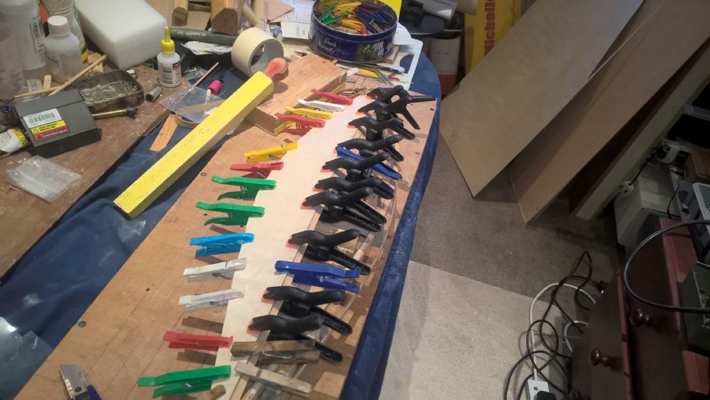
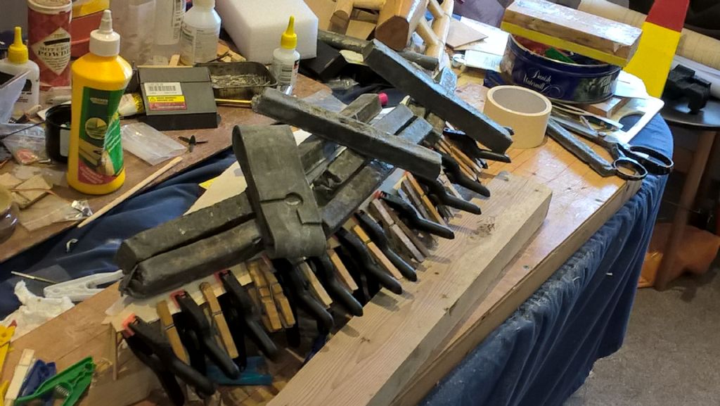
                            The keel line has been strapped with 3" masking tape across the joint, the stringer line just had as many clamps attached as physically possible. The top has then been weighed down with lead ingots/billets.

                            It is now a waiting game to see how the first stage as come out.

                            I have been trying to follow other threads to pick up as many tips, method as possible. I am amazed how skilled most (that should be all). I am also surprised that balsa seems to be used for the hulls of some. At the other end of the interval is one superbly carvel planked boat using pine strip.

                            #94307
                            Ray Wood 3
                            Participant
                              @raywood3

                              Hi Carl,

                              You are progressing well I know who to ask when I need some more lead for a keel

                              You could have used balsa wood to sheet your hull, and covered with glasscloth and epoxy resin it would have been as strong as ply and much easier to do ! but more expensive for the materials, the great thing about birch ply is you only need to seal it and then paint it job done.

                              Regards Ray

                              #94320
                              carl brotherton
                              Participant
                                @carlbrotherton75833

                                There is an irony, in that I have quite a lot of glass cloth, I also have enough Epoxy resin to have probably covered the hull.crying

                                However these days I much prefer to use "Water Based Varnish", much more convenient.

                                There is a lot to learn.

                                It took some time, but I figured out how to make a frameless hull. Although in my case the accuracy would be much less than guaranteed.

                                Regards

                                Carl

                                #94446
                                carl brotherton
                                Participant
                                  @carlbrotherton75833

                                  The hull is progressing, still further into territory that is unknown to me.

                                  wp_20210327_17_33_16_pro.jpg

                                  wp_20210327_17_33_30_pro.jpg

                                  It is more apparent than ever, that at least this plan assumes that the builder is more knowledgeable than me, probably with greater competence.

                                  There is a long list of "does this matter" and or "how do you do this", and "what is supposed to happen". which is a really long list of etc.

                                  I am hoping to get in a few beams and the Fin Box by about Monday.

                                  I am also starting on an attempts for a lead keel mold in the next few days. Again I am not sure at all how accurate a shape is seen as acceptable, the finish and the accuracy of the stipulated weight on the plan. Feed back would really be appreciated.

                                  #94477
                                  carl brotherton
                                  Participant
                                    @carlbrotherton75833

                                    wp_20210329_13_06_46_pro.jpgI am starting to grind to a halt. I do not what to do. The list is long.

                                    To many model boat builders, the answers are probably obvious, it may even be seen that you are stupid for not knowing, which in my case is true.

                                    wp_20210329_13_07_04_pro.jpg

                                    wp_20210329_13_06_46_pro.jpg

                                    My first question is it standard and desirable to cover the hull with surface/finishing cloth.at least

                                    A second is that the plan shows the rudder arm buried in the hull with so sort of hatch. I have noticed that at least one boat has the arm above deck. A few others have a sub deck "U" channel, which is open to the transom. From a practical view point an accessible arm seems better. What are modelers experience. I am personally more into practicalities, than aesthetics.

                                    #94516
                                    carl brotherton
                                    Participant
                                      @carlbrotherton75833

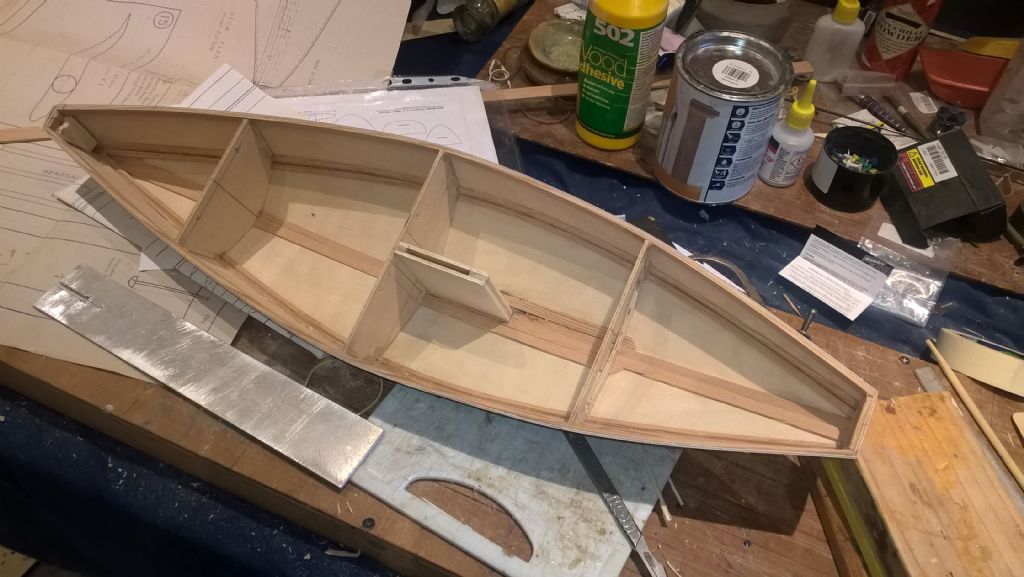
                                      The two front compartments are drawn as sealed chambers. I am not confident that I can ensure that in the long term that this situation can be guaranteed. On that basis I have been considering, making holes between the compartments to allow draining and also to permit any condensation to evaporate.

                                      What do people think?

                                      Also it seems that the decking is shown as what is probably one piece. I can see the benefit from the forward area being a single piece, the rest seems more amenable to multiple pieces.

                                      I have a couple of other issues. The first there is a description of how the apertures are constructed. Yet there is no indication of how the apertures should be closed, or are they typically left open?

                                      The second issue is with the batteries to power the Rx and Servos, these are shown as having a small hatch to the side of the Keel box. which seems to produce an asymmetric weight, small, but there. Does it not matter?

                                      #94594
                                      Steven S. 1
                                      Participant
                                        @stevens-1

                                        On my DF65 the battery pack is on the right and the RX and the winch and rudder servos are on the left. Kind of evens the load.

                                        Edited By Steven Shaw 1 on 04/04/2021 03:57:33

                                        #94596
                                        Malcolm Frary
                                        Participant
                                          @malcolmfrary95515

                                          On a racing type boat, and this was designed as such, it is normal practice to cover the holes with "hatch tape" "deck patches" or, as some call it, "sticky back plastic". Solid hatches are often held in place during sailing by tape, which is regarded as expendable.

                                          Other means used are solid hatches, either flush or over a coaming, held down against a gasket by tensioned clips. Commercial models invariably need a bit of modification in this area, if the threads covering them are to be believed.

                                          A bit of asymmetry in side to side weight distribution in the middle of the hull doesn't matter at all. The senior vote in where the weight is is the weight at the bottom of the fin, and that will be on the centre line.

                                          A small, easily removable hatch is needed for easy access to the switch and battery, and possibly to get a view of the receiver to check that it is operational. Working holes in the deck required for heavy maintenance should only be needed once in a while, and can have a more permanent fixing – hence the single use sticky back plastic, or a plate with fixing screws and a gasket.

                                          My take on waterproofing inside the hull is that a wooden hull needs everything it can get, but it has to be realised that a yacht leans over and getting a bit of damp inside is inevitable. An easy way to get rid of the damp* must be provided. Sealed compartments simply don't work. There is always a way in, but no viable way out. A good size hole high in a bulkhead will let unwanted water drain out with the boat on end, but prevent it sloshing about out on the water.

                                          Going back to the rudder arm placing – I much prefer above deck.  Easy access should work be needed on the rudder.  The hole where the control rod exits can be waterproofed by fitting a rubber bellows as used by power boaters.  Much the same thing is used by cyclists on brake cables.

                                          *Possibly a half pint or so of "damp" if conditions have been a bit exciting, but boats operated in damp air anyway.


                                          Edited By Malcolm Frary on 04/04/2021 09:51:39

                                          #94654
                                          carl brotherton
                                          Participant
                                            @carlbrotherton75833

                                            Yep, it does not seem logical to me to have sealed compartments, particularly when i am doing the building.

                                            On that basis I have made some apertures, highish up as suggested. I have also varnished the inside of the hull.

                                            The hull now weights 331g.

                                            wp_20210406_14_13_41_pro.jpg

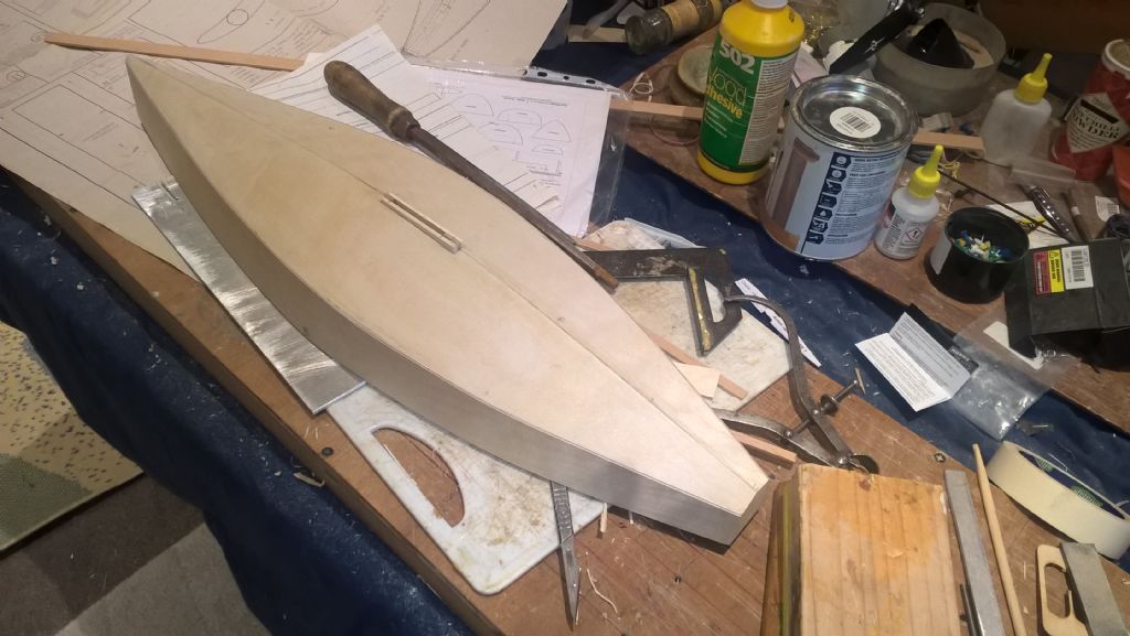
                                            I have started the process of casting a lead ballast bulb. That is by forming a wooden hole of approximately the correct size and dimensions. When cast, the shape will need some filling etc.

                                            wp_20210406_14_13_20_pro.jpg

                                            The weather is a bit to cold and windy to cast the ballast outside.

                                            I have another question what is the bumper made from, I have pine, and oak, balsa. Hopefully not rubber as I have non that is remotely suitable.

                                            #94656
                                            Malcolm Frary
                                            Participant
                                              @malcolmfrary95515

                                              RG65 rules

                                              Class Rules

                                              mandate a fender made of an "elastomeric material". That's for racing, but pleasure sailing only means that having such is a good idea to reduce damage to your yacht in the event of an overly sudden return to the bank or to prevent damage to other boats.

                                              Pine and oak do not deform, and so are more ramming devices. Balsa, if squidged, stays that way. D section fendering (in rubber) is available. I have heard of people using flip flop soles as donor material. One could be moulded using hot glue gun sticks, fixing to the bow probably using yet more hot glue. It taken about 20 years, but uses are emerging for the stuff. The Akela instructions suggested carving expanded polystyrene to shape, but that would probably act the same as balsa.

                                              https://www.radiosailing.co.uk/df65-front-bumpers-2-pk-1061-p.asp are available as spares for DF65. No idea how they match yours for size.

                                              #94657
                                              Tim Rowe
                                              Participant
                                                @timrowe83142

                                                As Malcolm says above. Another option, cheap and cheerful would be to carve some cork.

                                                With your stated level of experience I am concerned you could have a nasty accident trying to cast that lead.

                                                Lead fumes are poisonous

                                                Molten lead is hot. Could cause nasty burns and can set fire to things very easily.

                                                Unless that wood mould is completely dry. IE no moisture at all or the molten lead will flash it into steam and be propelled everywhere. Usually face, eyes, hands, arms and inside shoes.

                                                It looks like you are using pine which is full of resin which will gas and at the very least blow holes in your casting. At worst it can have a similar effect to moisture.

                                                If you are planning to cast two halves to bolt together, the mould might burn up and not last long enough for for the second pour.

                                                Please be warned.

                                                Tim R

                                                #94658
                                                Ray Wood 3
                                                Participant
                                                  @raywood3

                                                  Hi Carl,

                                                  That's good advice from Tim, I did post a picture of my plaster of paris keel mould taken from a balsa plug, it's on one of your many threads

                                                  Regards Ray

                                                  #94673
                                                  Malcolm Frary
                                                  Participant
                                                    @malcolmfrary95515

                                                    +1 on the cautions. Lead is useful, but dangerous stuff if mishandled at any temperature.

                                                    I had a more roundabout way of getting my ballast. I was going for a teardrop shape.

                                                    1 determine the volume. put the required amount of lead into a measuring jug. pour water in up to a marked level. Pour water into something handy, remove lead. pour water back in, bring up to level by dropping plasticine into the water. In my case, because I was doing it in two halves, half the weight.

                                                    2 Make the plasticine into the shape required. In my case, a full teardrop, so the shape, then whack it onto a solid flat surface. Shape was chosen such that the two halves would be symmetrical.

                                                    3 Coat the plasticine plug with thin grease like Vaseline. Take a plaster mould off it.

                                                    4 When set, dig the plasticine plug out and leave the mould to dry for a long time*, including giving it plenty of time in the oven. Total dryness is essential. *Several days, weeks are better.

                                                    Using the mould afterwards was much as described above. Pre heating and having it in a foil tray was deemed a good idea. If the plaster suffers a thermal shock, you don't want molten lead wandering over a concrete patio, even if it is outdoors and downwind. A plumbers ladle is a really good idea.

                                                    OTOH DF65 spare ballasts are available.

                                                    #94675
                                                    ashley needham
                                                    Participant
                                                      @ashleyneedham69188

                                                      Window drought proofing sponge strip makes a good bumper for boats. You can buy closed cell foam strip, self adhesive as well.

                                                      Ashley

                                                    Viewing 25 posts - 26 through 50 (of 87 total)
                                                    • Please log in to reply to this topic. Registering is free and easy using the links on the menu at the top of this page.

                                                    Code of conduct | Forum Help/FAQs

                                                    Advert

                                                    Latest Replies

                                                    Home Forums Beginners Topics

                                                    Viewing 25 topics - 1 through 25 (of 25 total)
                                                    Viewing 25 topics - 1 through 25 (of 25 total)

                                                    View full reply list.

                                                    Advert