Ballast Requirements (Boat Weights)
Ballast Requirements (Boat Weights)
- This topic has 46 replies, 7 voices, and was last updated 3 months, 2 weeks ago by
jcbryant.
- Please log in to reply to this topic. Registering is free and easy using the links on the menu at the top of this page.
Code of conduct | Forum Help/FAQs
Latest Replies
-
- Topic
- Voices
- Last Post
-
-
Eezebilt RAF Fire Boat
Started by:
Tim Cooper in: Build Blogs
- 2
-
26 minutes ago
 Dave Reed
-
Vic Smeed’s Silver Mist
1
2
…
32
33
Started by:
Bob Abell 2 in: Scratch build
- 3
-
46 minutes ago
 Colin Bishop
-
Feathered Friends
Started by:
 Chris Fellows
in: Soapbox
Chris Fellows
in: Soapbox
- 3
-
3 hours, 4 minutes ago
Chris Fellows
-
4D Modelshop
Started by:
Keith Long in: Scratch build
- 6
-
3 hours, 32 minutes ago
Chris Fellows
-
John Cobb’s Crusader
1
2
…
7
8
Started by:
 Paul T
in: Scratch build
Paul T
in: Scratch build
- 1
-
23 hours, 24 minutes ago
 John W E
-
Complex Automata
Started by:
Colin Bishop
in: Soapbox
- 1
-
2 days, 1 hour ago
Colin Bishop
-
Fairey Huntsman 31
1
2
…
5
6
Started by:
Chris Fellows
in: Build Blogs
- 14
-
2 days, 2 hours ago
Len Morris 2
-
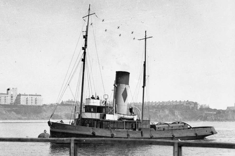
RAF Fireboat ID
Started by:
Dave Reed
in: Collectors’ corner
- 8
-
3 days, 3 hours ago
-
TID steam tug 42″ – PN Thomas drawing enlarged
1
2
Started by:
 Ray Wood 3
in: Scratch build
Ray Wood 3
in: Scratch build
- 8
-
3 days, 20 hours ago
 Richard Simpson
-
Lady of Skye (puffer)
1
2
Started by:
 mick east
in: Build Blogs
mick east
in: Build Blogs
- 9
-
4 days, 6 hours ago
Richard Simpson
-
Building a hull.
Started by:
mick east
in: Scratch build
- 7
-
6 days, 6 hours ago
Ray Wood 3
-
Todays Boating
1
2
…
210
211
Started by:
 ashley needham
in: All things floating
ashley needham
in: All things floating
- 84
-
6 days, 19 hours ago
Colin Bishop
-
Sea Rover Restoration
Started by:
harry smith 1 in: Collectors’ corner
- 4
-
6 days, 21 hours ago
Richard Simpson
-
WORKSHOP LIGHTING
Started by:
John W E
in: All things floating
- 9
-
1 week ago
Colin Bishop
-
Mayhem Website Down
Started by:
Colin Bishop
in: All things floating
- 4
-
1 week, 4 days ago
Colin Bishop
-
MAGGIE M trawler
Started by:
 sammyk
in: Buy/Sell or Trade
sammyk
in: Buy/Sell or Trade
- 2
-
1 week, 4 days ago
sammyk
-
Fairey Huntsman 28
1
2
…
7
8
Started by:
Chris Fellows
in: Build Blogs
- 1
-
1 week, 4 days ago
Chris Fellows
-
Fairey Faun
1
2
3
Started by:
Chris Fellows
in: Build Blogs
- 7
-
1 week, 6 days ago
Chris Fellows
-
meter
Started by:
 Alasdair Allan
in: All things floating
Alasdair Allan
in: All things floating
- 5
-
1 week, 6 days ago
Chris Fellows
-
River Queen 2”- 1’.
Started by:
Richard B in: Steam powered models
- 5
-
1 week, 6 days ago
-
Deluxe Superphatic Glue.
Started by:
Colin Bishop
in: All things floating
- 4
-
2 weeks ago
Chris Fellows
-
How to add photos to your posts
Started by:
Colin Bishop
in: Adding Images to Forum Posts
- 3
-
2 weeks ago
-
Cataract
Started by:
Bob Wilson in: Soapbox
- 2
-
2 weeks ago
Colin Bishop
-
The mighty tug Wattle
1
2
3
Started by:
mick east
in: Build Blogs
- 10
-
2 weeks, 1 day ago
Richard Simpson
-
Clyde Puffer Glenaray
1
2
3
Started by:
Alasdair Allan
in: Build Blogs
- 6
-
2 weeks, 3 days ago
Alasdair Allan
-
Eezebilt RAF Fire Boat


