RAf Crashtender

Advert

RAf Crashtender

Home Forums Building Kits RAf Crashtender

  • This topic is empty.
Viewing 10 posts - 1 through 10 (of 10 total)
  • Author
    Posts
  • #84238
    Anthony Barron
    Participant
      @anthonybarron19943

      Help Help. I am about to restore a 1960 RAF CrashTender. Lots of pics in your threads. I know it is 1960 as I was given the kit for my 10th birthday. Built by my Dad. Couple of years ago I went to the Model Boat Show in the midlands and after advice Purchased fittings, motor and speed control. A Leopard Hobby LC3536 and a Leopard brushless speed controller. I look at them both with utter bewilderment. Can anyone tell me how to mount the motor?? how the speed controller works??? I am unable to find information on line. Would it be an idea for find a club locally who may be able to advise. Believe there is a club in Harlow. Thank in advance

      Advert
      #6316
      Anthony Barron
      Participant
        @anthonybarron19943
        #84239
        ashley needham
        Participant
          @ashleyneedham69188

          Anthony. Welcome to the MB forum.

          Mounting the motor is easy. Screw that cross shaped bit of alloy to the motor (the "base plate" where the wires are attached to), and then screw the cross on to an angled mount….be it a bit of bent steel or a plywood bearer.

          THEN, it depends on which side of the motor the output shaft appears as to which way round the motor points, obviously the output shaft needs to point to the propshaft, SO the motor may be mounted in front of, or aft of, the engine bearer. 

          Some motors come with a prop adaptor that screws on the rotating drum bit of the motor and sometimes this simply has a plain shaft on it to use.

          The ESC of whatever type, marine or aircraft, has three wires for the motor, and black/red wires for the battery supply (red +) and one receiver lead.

          The three motor wires simply connect up to the three esc motor ones. If the motor runs the wrong way round, simply swap over any of the three leads.

          As to the esc works…..pfm.

          Ashley

          Edited By ashley needham on 21/10/2019 13:49:03

          Edited By ashley needham on 21/10/2019 13:55:24

          #84241
          Colin Bishop
          Moderator
            @colinbishop34627

            Anthony,

            I assume you have got the 30amp or 60am Leopard controller as sold by Component shop. I have two of the 30amp ones and it is really helpful to have the optional programming card.

            The various programming options are shown on the CS website:

            **LINK**

            This article on Brushless motors is worth a read although there is plenty of information on the web if you do a search.

            **LINK**

            Your motor spec is listed here:

            **LINK**

            Note that the motor shaft is 4mm in diameter when ordering a coupling.

            You can buy conventional mounts like this one but you need to find the right size.

            **LINK**

            Hopefully somebody can advise you on this.

            Colin

            #84244
            Dave Milbourn
            Participant
              @davemilbourn48782

              Anthony

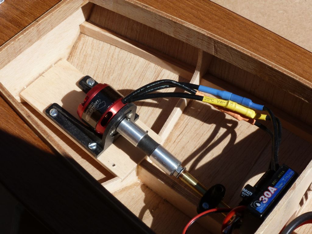
              I have a 28mm Leopard motor in one of my Hunstman 31 models, and the motor you have is similar although a bit larger. That being the case then you shoud buy a 540/600-size glass-nylon mount [it fits the 35mm Turnigy motors and they're pretty much identical to the Leopard one] and fit the motor as per the photo below. Remove the aircraft propellor-type fitting and use the plain end of the shaft to connect to the coupling. The coupling shown is not the type I favour now, which is the mini-flex one from SHG Marine Models. Expensive but the best.

              Dave M

              Huntsman 31 with Leopard motor

              Dave M

              Edited By Dave Milbourn on 21/10/2019 18:50:14

              #84249
              Dave Milbourn
              Participant
                @davemilbourn48782

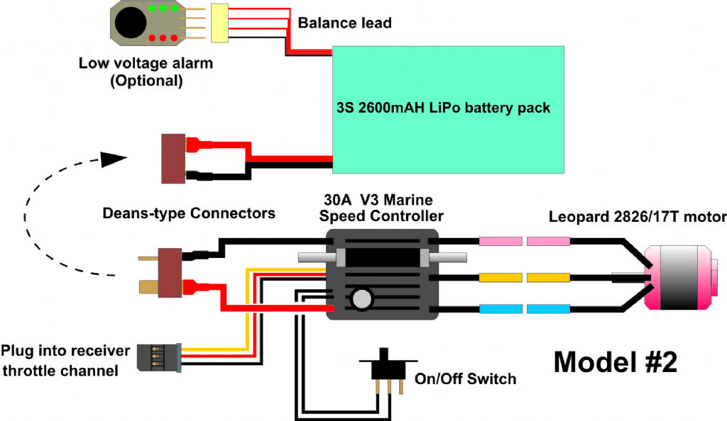
                Here is a wiring diagram for the motor, speed controller and battery pack. It shows a slightly different set of units to yours but the connections are identical. There is no need for a separate battery pack for the receiver, and the rudder servo simply plugs into the receiver where it's marked for model aircraft ailerons.

                brushless set-up.jpg

                #84250
                Anthony Barron
                Participant
                  @anthonybarron19943

                  Ashley, Colin & Dave Thanks for the information. It was fantastic. Not sure if I am repeating myself her but I don't think my reply went. If it is a repeat apologies.

                  The motor has a large spindle with a nut on to the rear. Is this also for mounting? I assume it wold need a bearing.

                  I read on line about 'Water Cooling' the speed control. Is this required or is it for racing boats? I see there are connections.

                  Again thanks and hope not a repeat.

                  #84251
                  Dave Milbourn
                  Participant
                    @davemilbourn48782

                    Anthony

                    At the risk of repeating myself, you should remove the aircraft propellor spindle entirely by taking out the four black securing screws [it's not required]; mount the fixed end of the motor to the glass-nylon bracket – that's the end with the three wires – and use the plain 4mm shaft to fit into the marine coupling. The picture shows this. You will need to purchase three gold-plated bullet connectors to solder to the three wires of the speed controller and mate with those already fitted to the motor wires.

                    DM

                    #84252
                    Anthony Barron
                    Participant
                      @anthonybarron19943

                      Thanks Dave. Just had a closer look at the motor. Able to remove the propellor spindle. All wires have colour coded bullet connections for the speed control.

                      #84255
                      Colin Bishop
                      Moderator
                        @colinbishop34627

                        As said by Ashley earlier, just connect up the three wires in any combination. If the model then goes backwards when it should go forwards then swap any two over. Not sure just why it works but it does!

                        As far as the reading material is concerned, with a bit of concentration it all becomes fairly clear and you have learned a lot in the meantime.

                        Colin

                      Viewing 10 posts - 1 through 10 (of 10 total)
                      • Please log in to reply to this topic. Registering is free and easy using the links on the menu at the top of this page.

                      Code of conduct | Forum Help/FAQs

                      Advert

                      Latest Replies

                      Home Forums Building Kits Topics

                      Viewing 25 topics - 1 through 25 (of 25 total)
                      Viewing 25 topics - 1 through 25 (of 25 total)

                      View full reply list.

                      Advert

                      Newsletter Sign-up