The world's leading magazine for all model boating interests
Sir Lancelot
Sir Lancelot
Home › Forums › Building Kits › Sir Lancelot
- This topic is empty.
-
AuthorPosts
-
2 September 2010 at 09:57 #28238
Robin Lee
Participant@robinlee31938Hi PaulThe kit winch is amazingly complex. I suppose that is reflected in the kit price. Looks worth the money. Should make a pretty good winch.RegardsRobin2 September 2010 at 21:09 #28239Paul Godfrey
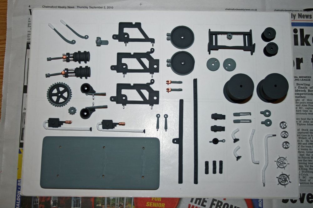
Participant@paulgodfrey14946Hi Robin,Yes, it should look the business when completed (hopefully!).I have since noticed a few discrepencies though. Firstly, you will see from the photo of the parts that there are two ‘hand wheels’ (to the left of the wooden base, at the bottom) – part number W28, and the parts listing does show that there should be this amount. However, the diagram above shows three. Secondly, there are three smaller ‘brake wheels’ seen to the left of the hand wheels, but the parts listing states there should be two, and the diagram shows one!!Furthermore, I believe that the small gear, part W10, should be on the other shaft near to the one it’s shown on in the diagram.‘Modeller’s licence’ will once again prevail, and I will use the bits I have – it won’t look any worse for it!!Paul.3 September 2010 at 19:04 #28251Wallace Manning
Participant@wallacemanning93491Hi Paul have fun in the build of the winch it took me two goes to get it right I have a photo on my build.Hoping to get mine back any day now the lights are all done then I can start to build up .wallace9 September 2010 at 20:37 #28293Paul Godfrey
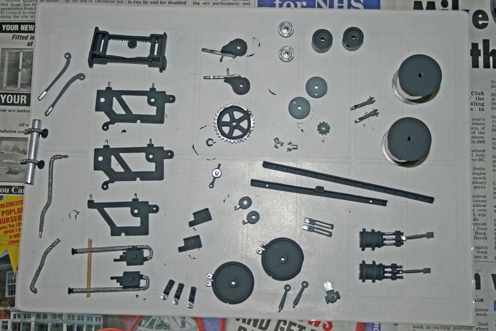
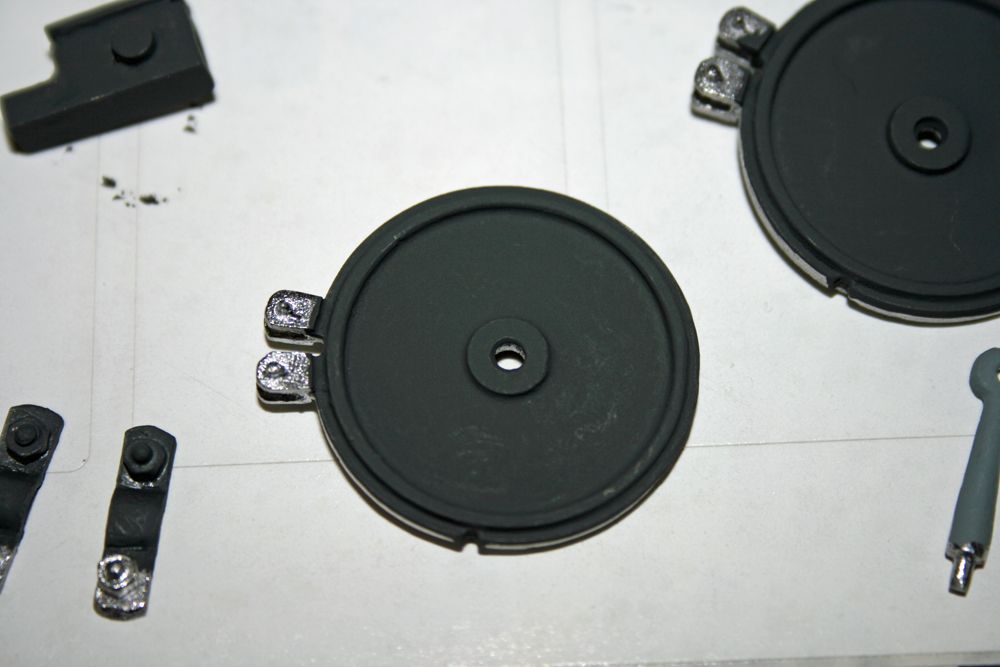
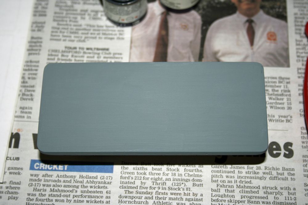
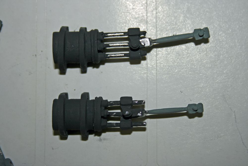
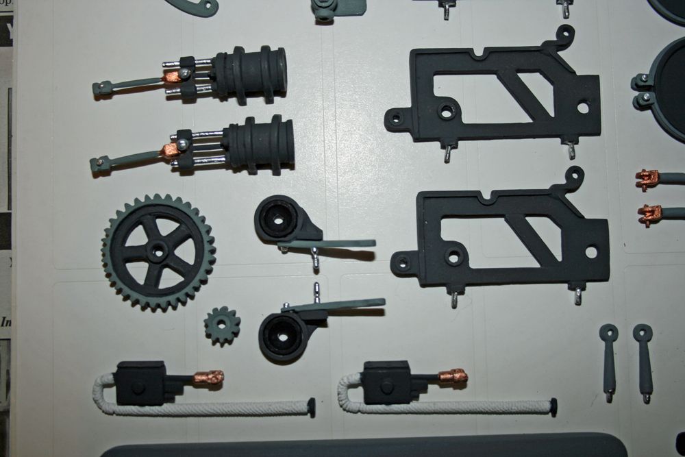
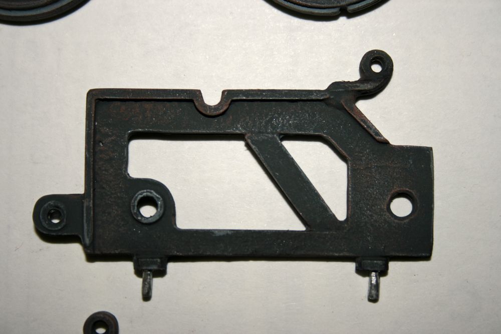
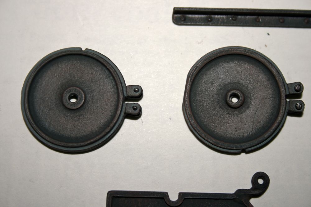
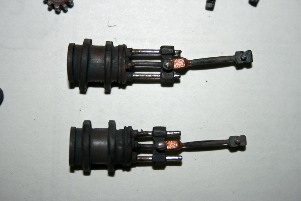
Participant@paulgodfrey14946WINCH CONSTRUCTION Part 2Just a few photos to show the progress of the winch.The first shows most of the components with painting commenced. In an earlier photo, the white-metal parts had been cleaned up, wire-brushed, and washed in soapy water. I generally tend to simply hand-paint most of the components directly with Humbrol enamel prior to assembly (it’s even more time consuming trying to mount the parts for spraying, especially the tiny bits!):The main colour for the winch, I have decided, is dark grey, and some of the parts shown above have had an initial coat of this where necessary. Other parts will be painted in a medium grey to give a contrast, there’ll be some black here and there, white pipe lagging, and some silver & copper. The next photo shows a brake wheel – in a later photo, I have painted the band around the outside in the medium grey, and the bolts in silver.Here is the much sanded & primed base:And here’s the partially painted steam cylinder units:The main units are dark grey, as are the sliders, and the conecting rods medium grey. The next photo shows these units, and a few of the other items, fully painted (but not yet weathered):Finally for now, all of the components. Most are fully painted, but not weathered – that will be the next installment. They will also be ‘highlighted’, which will define their edges and make them stand out more. The hand & brake wheels will be painted once they’ve been attached to their rods.Edited By Paul Godfrey on 09/09/2010 20:38:05
16 September 2010 at 20:45 #28387Paul Godfrey
Participant@paulgodfrey14946WINCH CONSTRUCTION Part 3Just a few photos of some of the components fully painted & weathered. As mentioned before, I first ‘highlighted’ the parts by dry brushing with a lighter shade of grey, and then applying some rust & grime, again by dry brushing.Construction of the winch has now started, and some more photos will follow in a few days time.Paul.Edited By Paul Godfrey on 16/09/2010 20:46:16
20 September 2010 at 20:44 #28422Paul Godfrey
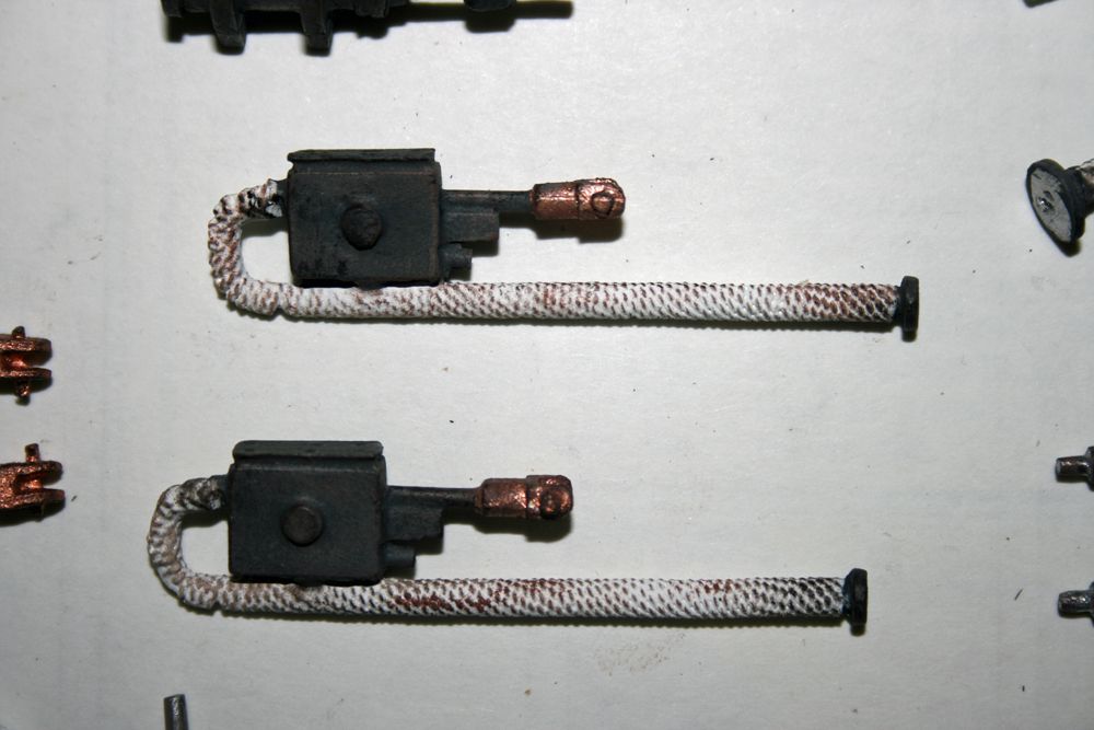
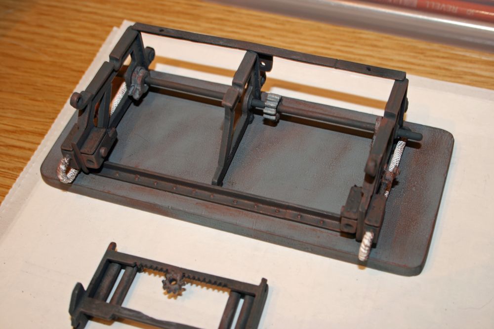
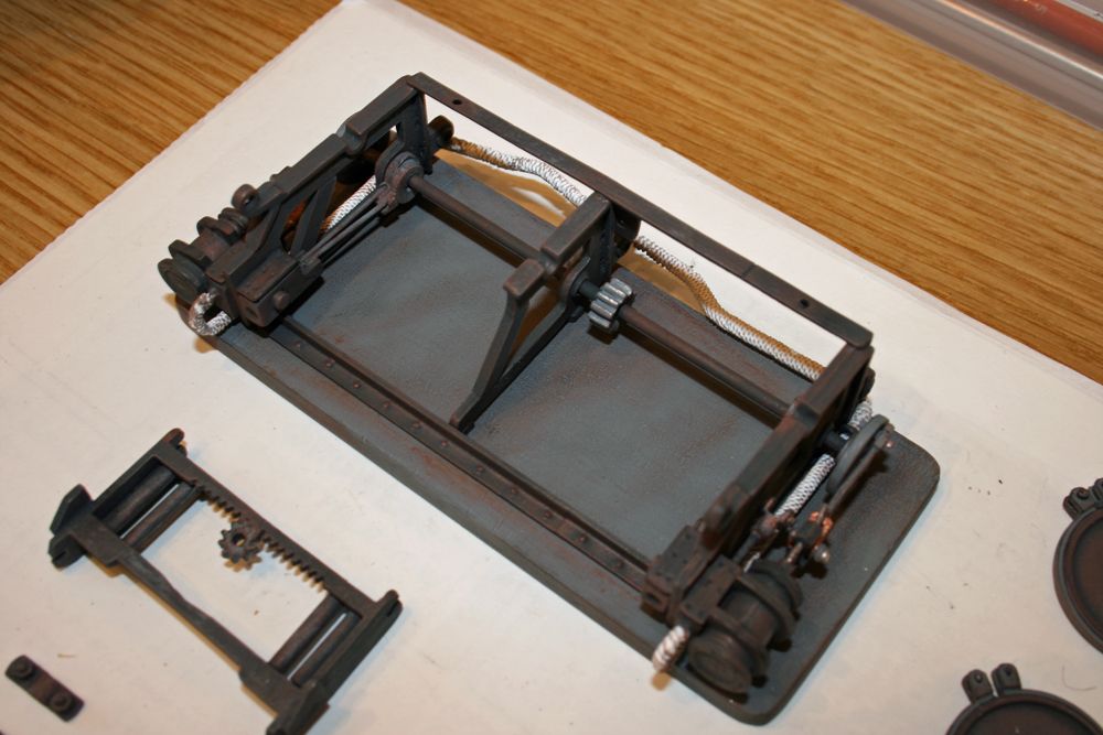
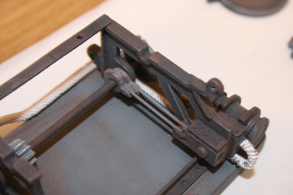
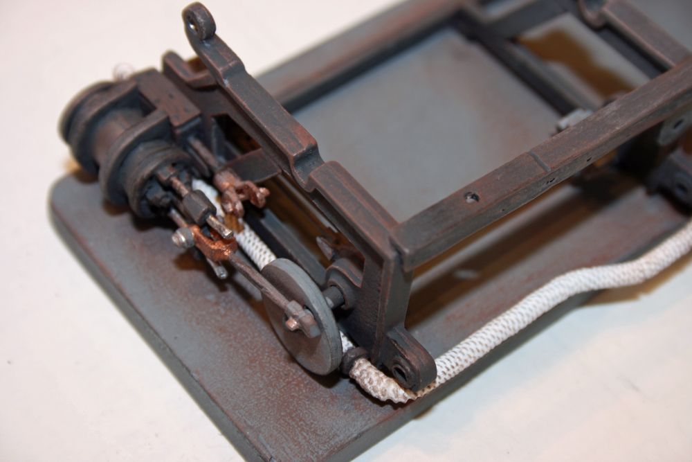
Participant@paulgodfrey14946WINCH CONSTRUCTION Part 4The winch is now complete, and I will split the construction photos and notes over two postings. I should get them both done this evening.The first photo shows the outer and central frames mounted onto the baseboard – the instructions give the measurements for the mounting holes (see the photo in part 2). It should be noted that it is advisable to open-out all holes in the frames (and other components) before assembly, as it may be difficult to do this afterwards – there are various shafts which pass through the frames, such as the one fitted below. Also shown below are the inner and outer steam chests, the latter having the lagged steam inlet pipes which run down each side to the rear:The next pic shows the steam cylinders and some of the linkages fitted:There are 1mm wire rods which fit between the inner steam chests and the eccentric cams on the rear lower shaft, seen above and in the photo below:And finally for this post, a close-up of the steam cylinders and the linkages fitted, together with one of the steam inlet pipes at the rear of the winch:20 September 2010 at 21:22 #28423Paul Godfrey
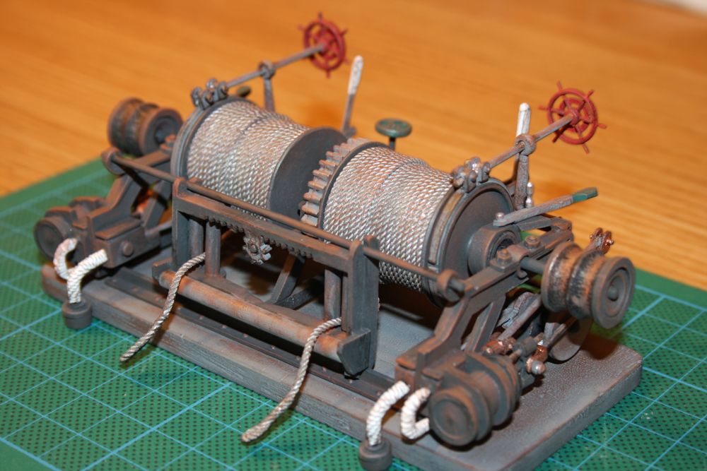
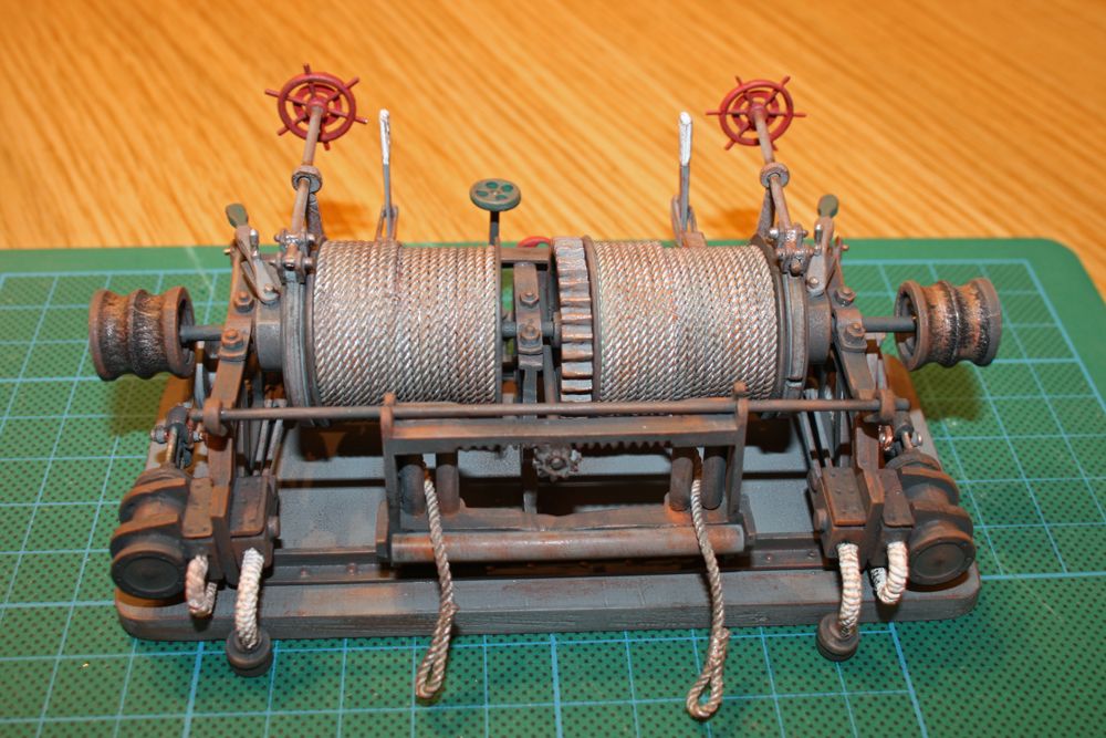
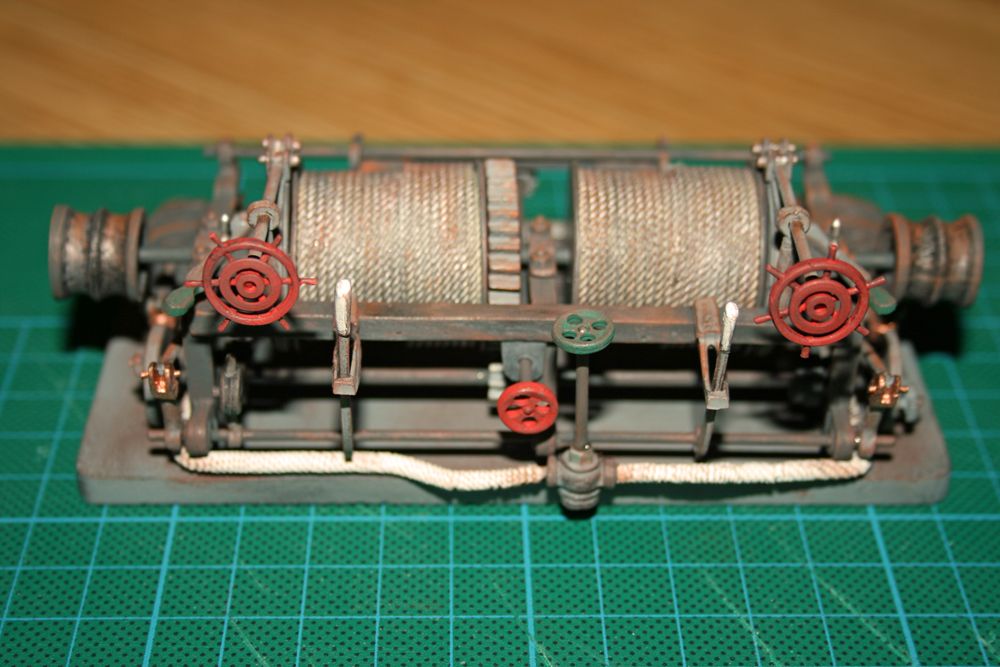
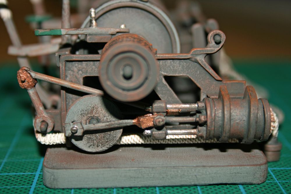
Participant@paulgodfrey14946WINCH CONSTRUCTION Part 5The remainder of the winch construction is quite straightforward, if not a little fiddly at times, but I would like to describe how I attach the rope to the drums (no photos taken during this stage, only the finished items unfortunately!).1) The end of the length of rope is glued to the outside edge of the drum, and left to dry.2) Using a pointed wooden spatula (coffee shop stirrer, with the end trimmed to a point), I then apply a line of thick superglue from the outside edge of the drum which has the rope attached to it, towards the opposite side of the drum. This is done three times, equally spaced around the drum, but only half way across at this stage.3) The rope is wound around the drum up to where the glue finishes, and held for a few minutes until the rope is stuck.4) Glue is then applied across the remainder of the drum, and the rope wound around to the edge, and again held in place until the rope has stuck. At this point, a single layer of rope covers the whole drum.5) As in 2) above, glue is applied but this time on top of the existing layer of rope, and the rope wound around, heading back in the opposite direction, to approximately half way across.6) Once all is fully dry, I lightly painted the rope with a mixture of silver and light grey. Onto this, rust coloured paint was dry-brushed, followed by some black, to give the finished result.Although all the winch components were given an initial weathering prior to assembly, once it was finished, additional layers of dry-brushed greys, rust, black etc were added to produce the final effect.Some more photos of the completed winch:And finally, a close-up of the side showing all the linkages to the steam cylinders, steam chests, and reverse shaft:21 September 2010 at 09:45 #28424Wallace Manning
Participant@wallacemanning93491Paul its looking realy good the two of our winch’s side by side would show the new and the old well done its coming along just great.wallace21 September 2010 at 17:26 #28429Robin Lee
Participant@robinlee31938Hi Paul, your winch looks very realistic – ready to chuff into action! I bet when you were sticking the rope to the winch drums you had a thought on the lines of going beyond the point of no return here and keeping your fingers crossed. RegardsRobin21 September 2010 at 20:51 #28432
Paul Godfrey
Participant@paulgodfrey14946Thanks Wallace & Robin for your comments.I did find the glueing of the ropes the most nerve-racking part of the winch build. But – I have learnt from the smaller hand-winches seen on the foredeck & stern grating that it is far better to use thick superglue, as thin superglue tends to be absorbed more by the rope, and changes the colour of rope in that area (thick superglue doesn’t dry as quick either, giving a longer time to wrap the rope around).Robin – well done at the Nats by the way, maybe one day I’ll get somewhere near to your very high build quality, but doubt it!Wallace – you must be getting close to the maiden voyage of your S.L.! Look forward to seeing photos of your boat in the water.Regards, Paul.22 September 2010 at 17:59 #28438Robin Lee
Participant@robinlee31938Hi PaulThanks for your comment. On the matter of build quality you are too modest, Sir Lancelot is of a very high quality – ideal for next year’s nats in fact. Mind you we don’t know how well Sir L will reverse and these nats organisers do seem very fond of trcky reverse manoeuvres! Regards Robin23 September 2010 at 19:14 #28442
Paul Godfrey
Participant@paulgodfrey14946Robin,I’m not very hopeful of it being that manoueverable!! In fact, I’m wondering if our lake is wide enough for it to turn in one go!Regards, Paul.30 September 2010 at 19:05 #28476Paul Godfrey
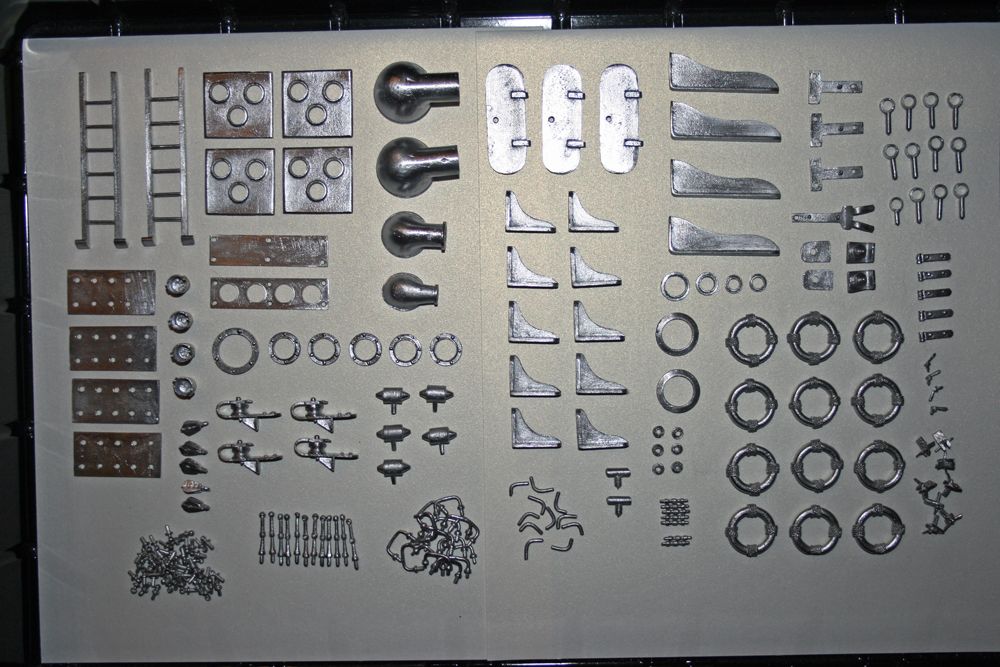
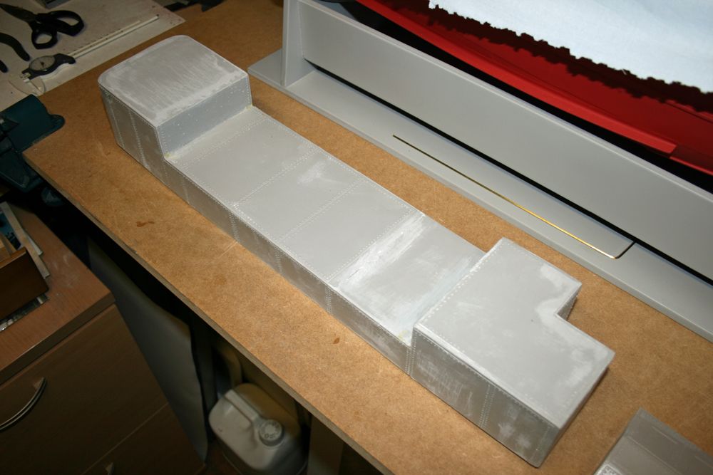
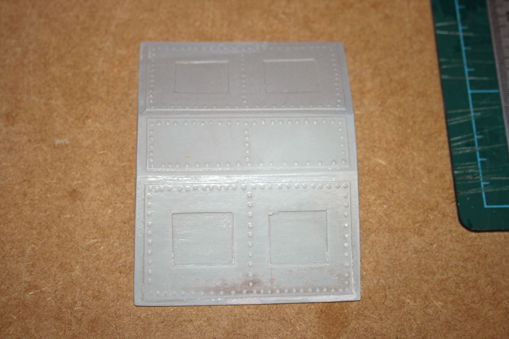
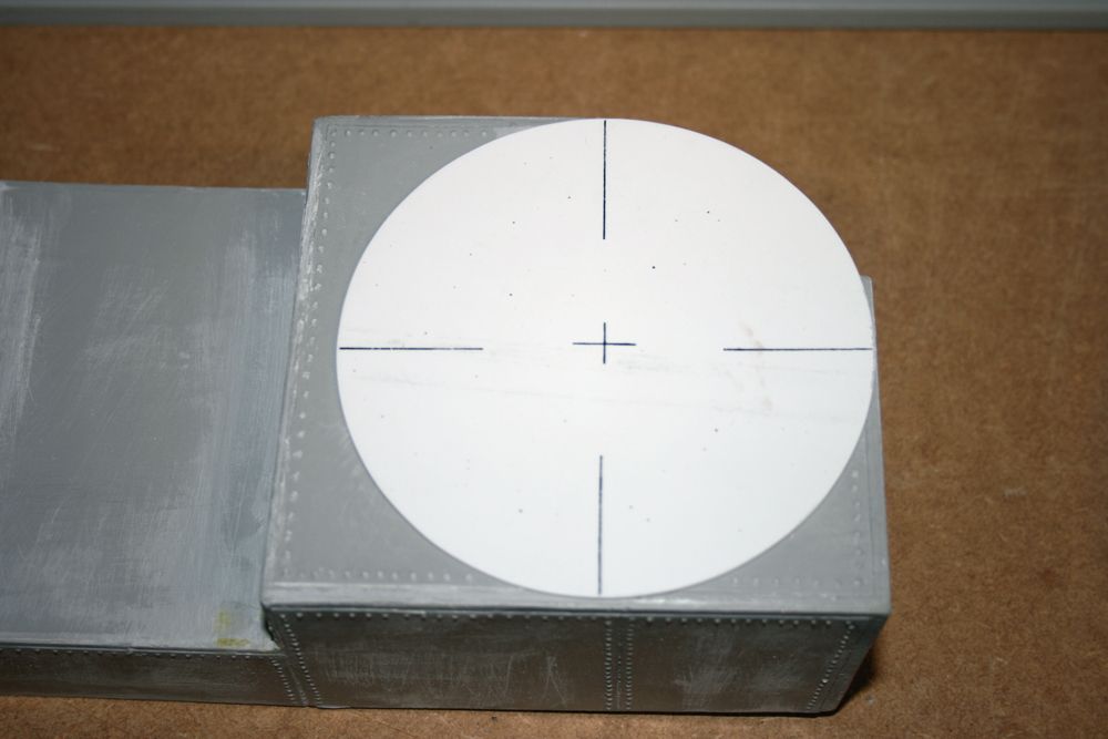
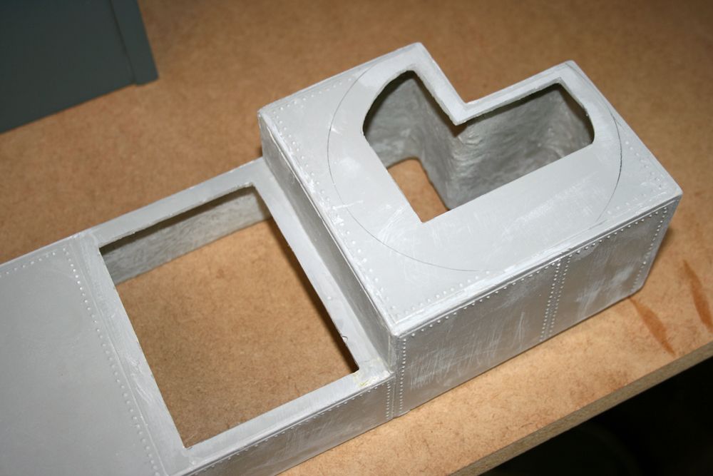
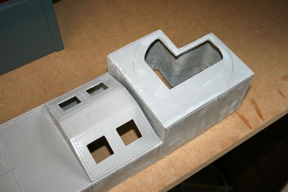
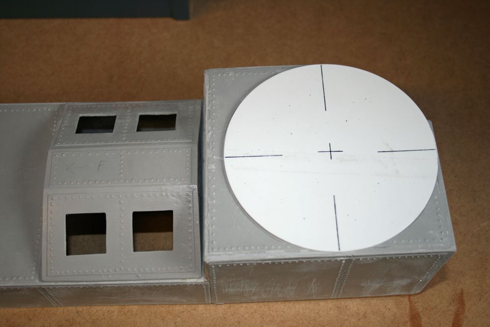
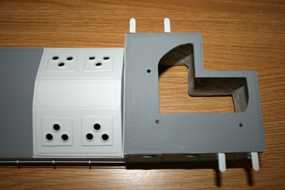
Participant@paulgodfrey14946I’ve now started work on the superstructure, and as usual with my posts, begin with a photo of the 200+ white metal components, all of which relate to just the lower superstructure fibreglass moulding:The next pics are of the superstructure & engine room skylight fibreglass mouldings, with some initial filling & sanding carried out:You may recall the electronics tray from earlier in the build, and the rear ‘extension’ which houses the various switches & charging jacks. This was designed in such a way that the switches could be accessed by removing the rear gun tub – an ideal location as 1) the superstructure is higher at this point, giving more room for the extension & switches, and 2) the gun tub does not have any rigging, support rods etc going to it, so is very easy to remove for the access required. I started by cutting out the gun tub base, and positioning it on the superstructure so that I could draw around it to show where I could cut out the hole:It was then a case of cutting out sufficient material to allow access to all the switches & charging jacks:You will also see the cut-out for the engine room skylight moulding , which itself has had four openings made in it to accept the four white metal skylights, each with three circular windows. This will be illuminated in the future.And finally, a photo of the gun tub base in position. Whilst held in place, this will have two or three small holes drilled through it and the fibreglass, and some locating pegs bonded to it. Not sure what I’ll use yet, possibly some flat-headed tacks or similar, which can be pushed through and bonded to the gun tub base. These will be barely visible once the gun tub has been built up, and will allow the unit to be simply and accurately attached / detached for easy access.24 October 2010 at 18:41 #28669Paul Godfrey
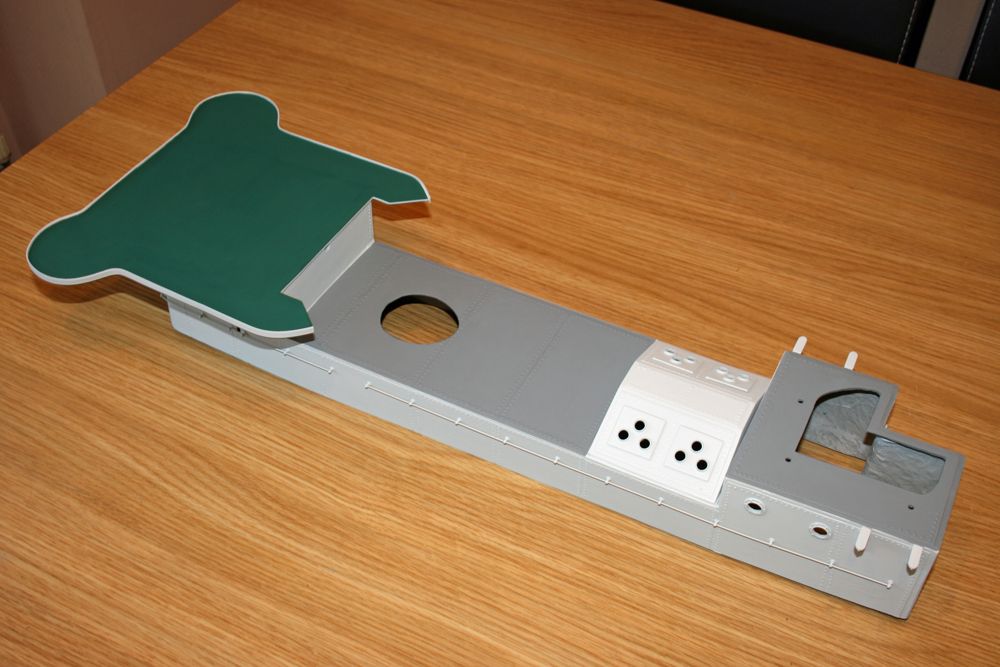
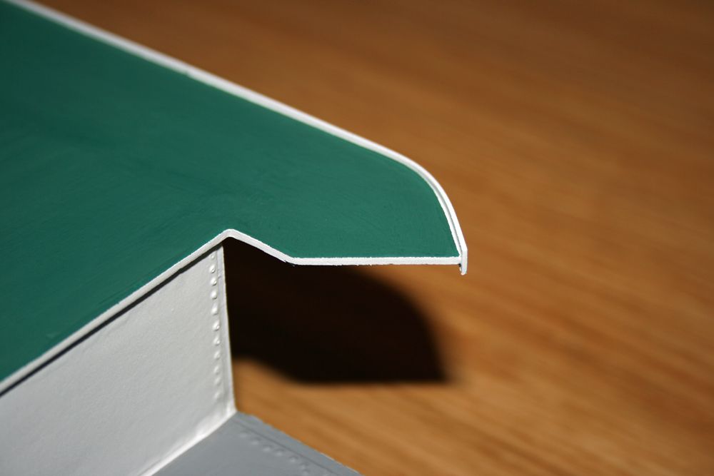
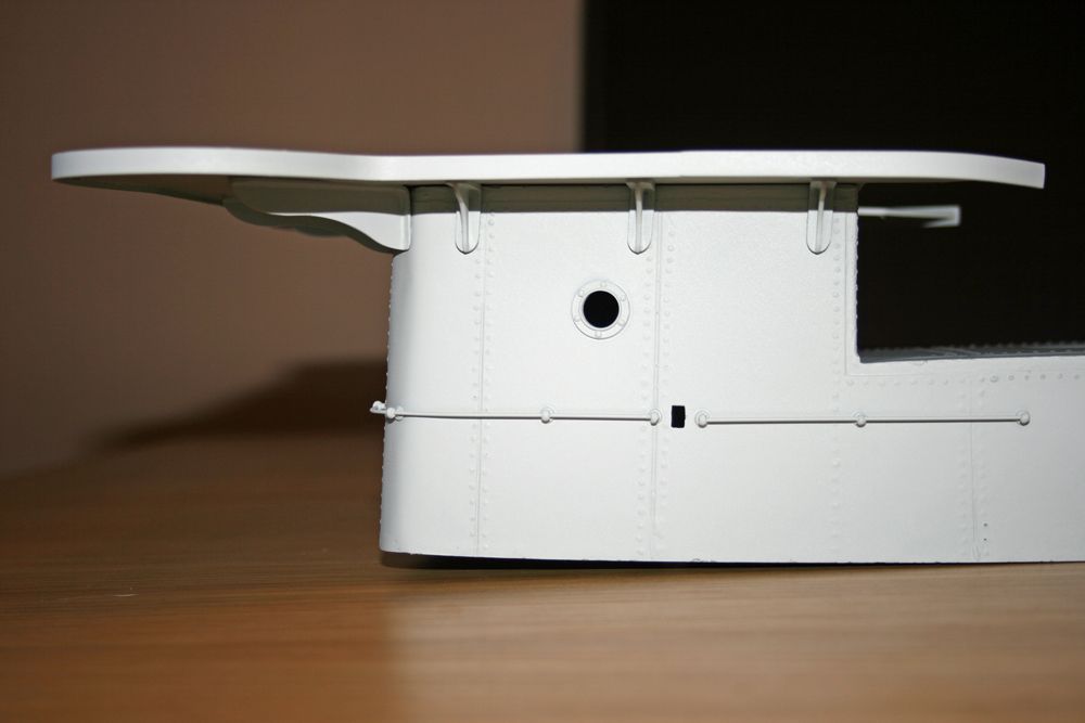
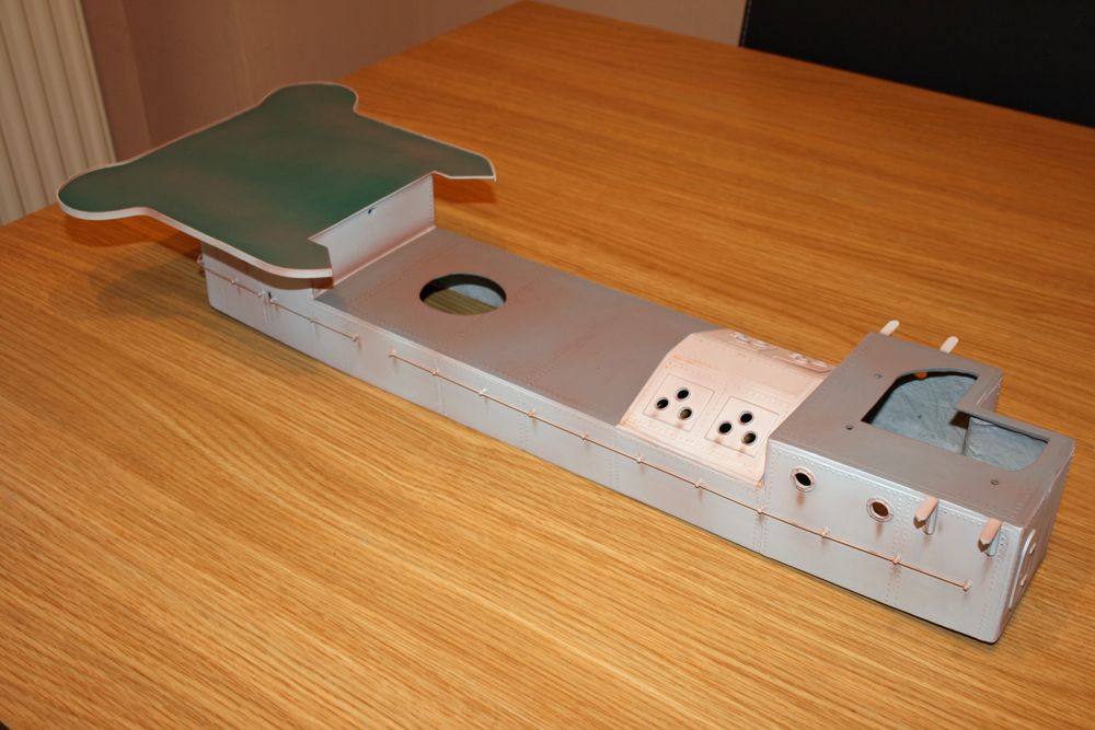
Participant@paulgodfrey14946Work on the superstructure has continued, and the next photo shows progress to date – apart from the weathering, which is shown in the last photo of this particular posting:To get to the above stage, the following has been done:1) After cutting out the openings for the funnel, skylight moulding, and the switch access as seen in the previous posting, further holes were made for the six portholes, and the handrail stanchions.2) The portholes, stanchions & handrails, three doors at the rear, the skylight moulding with skylights attached, and the rear ammunition box supports were all fixed to the superstructure.3) The wheelhouse deck was cut out, and bonded to the front of the superstructure – this was done at this stage so that the deck supports could be glued to both the deck underside and the superstructure at the same time, and it would make step 4 below easier.4) The 5mm wide ply strip was cut out and fixed to the perimeter of the wheelhouse deck.5) The whole assembly was sprayed with two coats of Halfords grey primer.6) It was then sprayed with two coats of the Humbrol light grey as used for the hull.7) The deck was painted with Humbrol deck green, as used for the main deck.8) The superstructure ‘roof’ was painted with the darker Humbrol grey, as used for the foredeck (note – the skylight moulding is the same colour as the superstructure sides, but appears lighter in the photo due to the effect of the camera flash).The next photo shows a close-up of the wheelhouse deck, and the need for some fiddly masking of the vertical ply strip and rear edge:The following pic shows the upper rear section of the superstructure. The two supports for each ammunition box can be seen on either side, along with the skylight moulding with the four white metal skylights. Notice also the three mounting holes for the removable gun turret, as described in the last posting. The turret base was placed in position, and holes drilled through into the superstructure. The turret will be described fully in the future.In the next photo, the supports for the wheelhouse deck can be seen – there are three shorter supports each side, and four longer ones at the front. You can also see a small rectangular cut-out between the handrails – this is the access hole for the smoke generator adjusting / shut-off valve, as described in a previous post. The position of this was accertained by placing a metal block with a pencil taped to the top, onto the deck adjacent to the hole on the superstructure coaming, with the pencil tip pointing directly towards the hole. The superstructure was then lowered into place, and the pencil used to mark the position of where the hole needed to be made. I was glad I did this before feeding the handrails through the already attached stanchions! I shall leave the hole uncovered, as to me it looks quite inconspicuous, and part of the boat.Finally for this update, a photo of the weathered superstructure. This was done in the same way as the hull, ie an airbrush was used for general surface rust, followed by some dry brushing with both rust & matt orange humbrol enamels to highlight certain areas.25 October 2010 at 19:28 #28676Wallace Manning
Participant@wallacemanning93491Its looking better every posting Paul answer to your question Paul I dont know when mine will be in the water still alot to bee done have been poorly again for the past five weeks just getting back into it posted a few more photos .wallace25 October 2010 at 20:27 #28678Paul Godfrey
Participant@paulgodfrey14946Hi WallaceSorry to hear you’ve been unwell, hope you’re now back to full health.I’ve had a look at your latest photos, and the boat’s comming along very nicely indeed, it’s looking great.I’m about to start the lighting – hope I can get it looking as good as yours.Best wishes, Paul.26 October 2010 at 16:05 #28686Robin Lee
Participant@robinlee31938Hi Paul, all looking very neat and tidy, a question on your step 4) – “The 5mm wide ply strip was cut out and fixed to the perimeter of the wheelhouse deck.”The edge of the deck looks complex with some sharp corners. Did the ply strip part come pre-shaped or did you have to shape it yourself? How have you prepared it for painting?RegardsRobin26 October 2010 at 19:57 #28689Paul Godfrey
Participant@paulgodfrey14946Hi Robin, & thanks once again.This is simply 5mm strips cut from the end of one of the supplied ply sheets (cut across the grain of course, as mentioned in the instructions), and glued to the edge of the deck with PVA glue. As the ply was thin, it bent easily to the shape of the deck, and was held in place with masking tape overnight while the glue dried.The strip around the front gun platform was done in the same way.The deck itself was cut from a much thicker ply sheet, which had the shape of the deck hand-drawn onto it. It was given a couple of coats of sanding sealer, and sanded after each coat. The strip was attached as above, and this was given a coat of sanding sealer afterwards. The two coats of Halfords primer (sanded between coats) gave a nice smooth finish on which to paint the final coats of deck green.I started preparing for the lighting tonight, but won’t attach anything until superstructure has beensprayed with matt varnish (Wickes, mixed 50/50 with enamel thinners – worked extremely well on the hull & decks), and glazing added. Next post in a week or two will cover this.RegardsPaul.29 October 2010 at 19:21 #28726Wallace Manning
Participant@wallacemanning93491Paul did you use matt varnish on all the boat and where did you get wickes varnish from is it good I have never put varnish on my hulls or superstruct only on the decks after primer and deck green to really make it waterproof as I have alot of brass on my boat what would you use to stop the brass from going off etc.Take care im keeping a watch on the build well done.Many thanks for your kind words still feeling week not done anything to my boat. wallace30 October 2010 at 19:35 #28737Paul Godfrey
Participant@paulgodfrey14946Hi Wallace,Wickes is a d.i.y chain store, like B&Q, but smaller – don’t know if you have them in you neck of the woods, but the reason I bought their varnish (yes, it is matt) is that it is polyurethane based, which is the recommended stuff to use. I mix it 50/50 with enamel thinners, and spray it with my basic Badger airbrush.Many varnishes available today are the ‘quick-drying’ type, and are not polyurethane based. I must admit I can’t remember why they’re not as good, possibly its to do with yellowing over time, or incompatabilty with certain paints – I’m sure someone will clarify this for us!Varnish is good for a few reasons. It gives protection to the paintwork against the inevitable knocks & scrapes our boats have; it adds a degree of waterproofing as you state; it improves the look of hand-painted areas, such as decks, by helping to obscure the brush marks, and so on.I’m unsure what would be good protection for brass, and therefore wouldn’t want to hazzard a guess. If this question hasn’t already been asked on this or other forums, suggest you pose the question yourself on a new thread – someone out there will know the answer (hopefully!!).All the best Wallace,Paul.7 November 2010 at 15:59 #28798Paul Godfrey
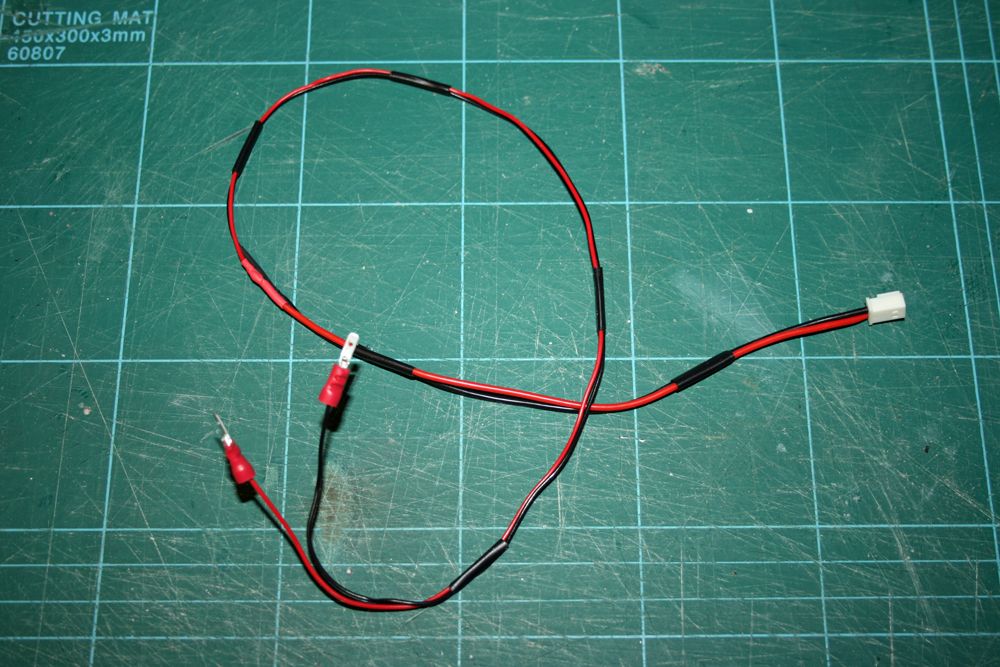
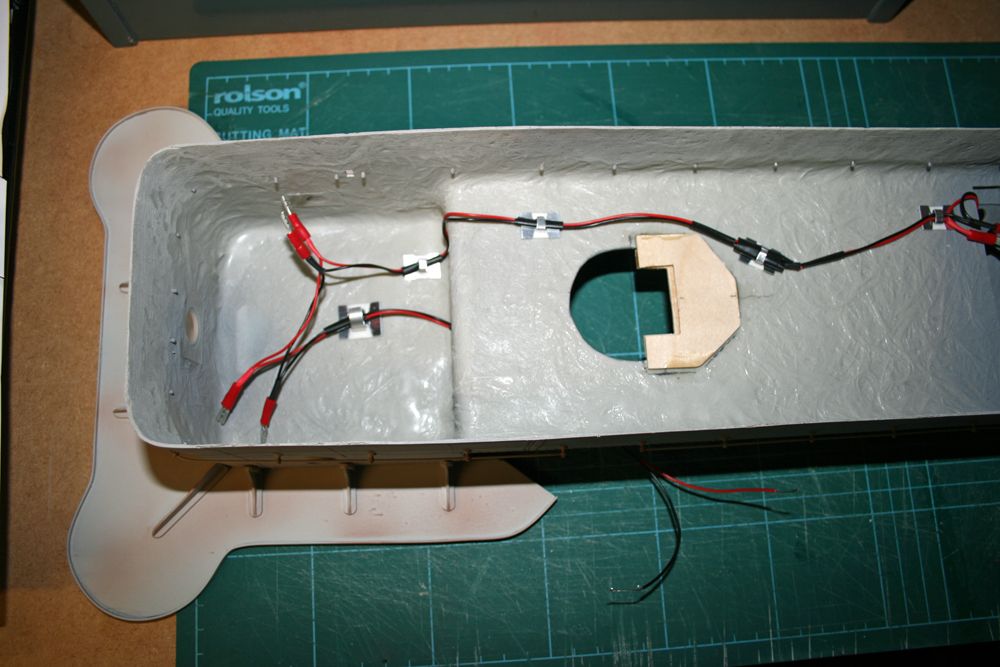
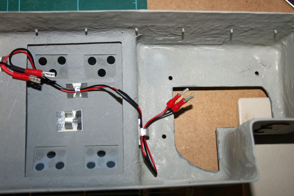
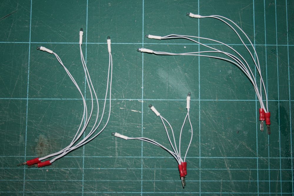
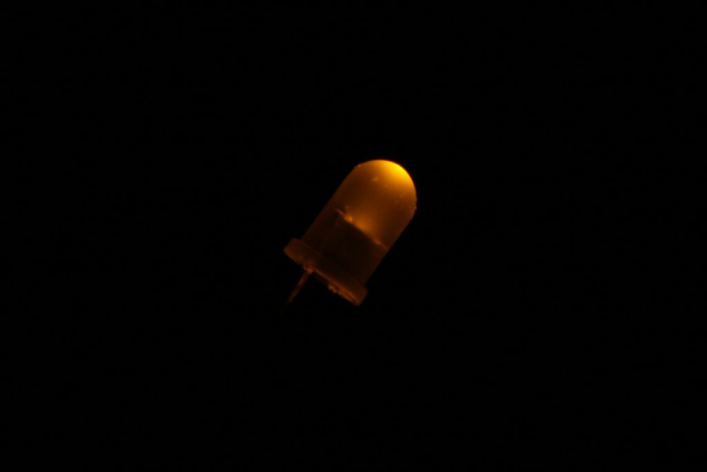
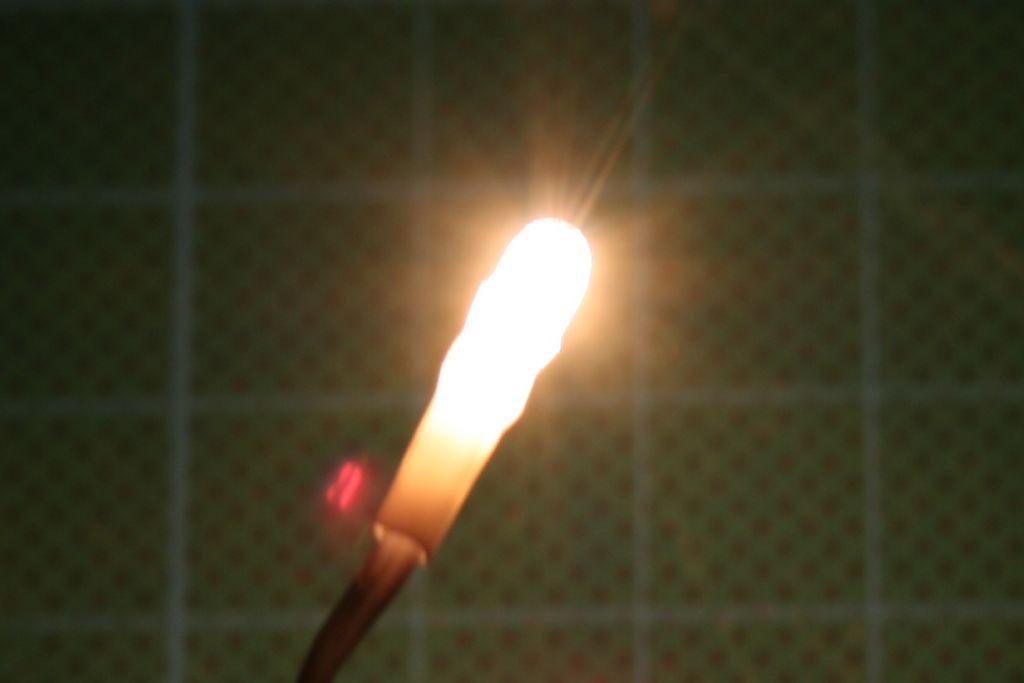
Participant@paulgodfrey14946The first of two updates today, this one relating to the start of the wiring for the lighting.There will be two seperate circuits for the lights in this boat, one of them will run throughout the removable superstructure, and the other will run beneath the deck, for the lights that will be fitted inside the companionways, escape scuttles, etc. The circuits will have their own connectors, so when the superstructure needs removing, only the connector to that circuit will need to be disconnected – the other connector will only need to be disconnected if the electronics tray needs to be removed.You may have noticed the two connectors in photos of the electronics tray in earlier posts, this next photo shows the wiring that connects the tray to the seperate wiring loom fitted to the underside of the lower superstructure:The white connector is at the tray end, with the red crimped connectors going to the wiring loom as shown in the following two photos:You will see from the above photographs that the wiring loom is clipped to the underside of the superstructure (and therefore removable if required), and has four sets of crimped connectors. One of the pairs seen at the front will connect to the wiring seen in the first photo, and the other three (one at the front, one at the skylight, and the third at the rear of the superstructure) will have ‘mini’ looms, each with three lights, connected to them:These lighting looms have been made up by soldering one wire from each individual light together, then crimping on the connector. Once attached to the main lighting loom, the lights will be clipped to the underside of the superstructure, and therefore removable should a bulb need replacing.Now, you will see that I’ve used grain of wheat bulbs, and not LEDs as previously stated. Why? – take a look at the following two photos which were taken at night with exactly the same manual settings on my camera. First, the 12V LED:And next, the grain of wheat:Enough said!!I know you can get ultra bright LEDs, but not 12V as far as I am aware, so a resistor would be required meaning more faffing about, and they also take up alot more space. In any case, the bulb gives off light at a much broader angle, and appears more natural.With regards to bulbs blowing in the wheelhouse, spotlight, and navigation lights, these will also be accessible & removable, so no worries there.As previously mentioned, I needed to fit the lights to the underside of the superstructure before adding the many detail parts to this component. It also soon occurred to me that the boat deck, carly float mount, and the funnel will need to be attached before building up the superstructure detail, as they need mounting holes drilling in the superstructure, which I would not want to do when its all built up. The next post which will follow today describes the start of these items.Paul.Edited By Paul Godfrey on 07/11/2010 16:01:22
7 November 2010 at 18:06 #28802Paul Godfrey
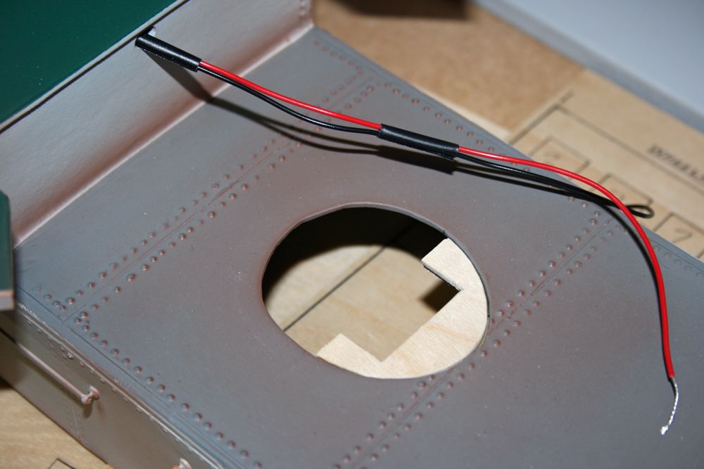
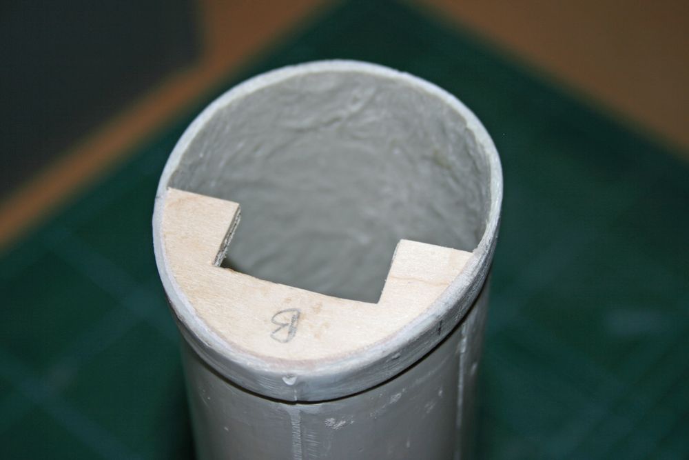
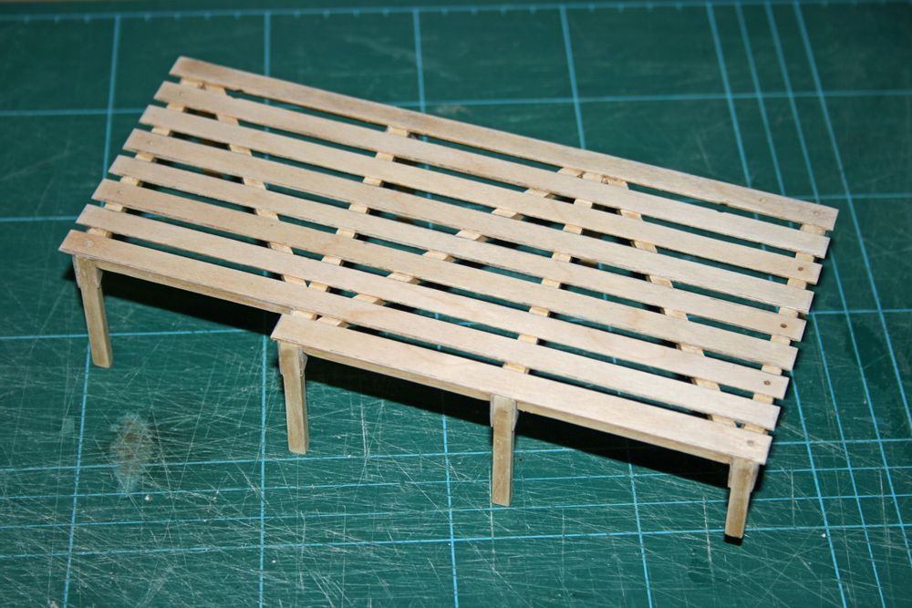
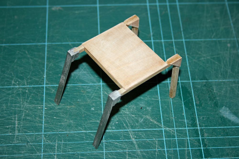
Participant@paulgodfrey14946Continuing on from my post earlier today, the following photo shows a branch of the wiring loom for the superstructure lighting emerging from a hole cut in the fibreglass moulding. Above this hole will be the rear extension to the wheelhouse which, on the full size boat, contained the steering engine. The wires will pass up into this, and join to another wiring loom which will be attached to the underside of the wheelhouse roof (to be made removable, of course!). Bulbs will be attached to light the wheelhouse, and seperate wires will run to the spotlight (immediately above the steering engine extension), and the navigation lights.You can also see in the above photo (and in a photo in the earlier post today) the mount for the funnel. Firstly, a piece of ply larger than the hole was epoxied in place from the inside, then another piece following the cut of the hole was bonded on top. This brings it flush with the top surface of the superstructure. The cut-out shape in the middle allows for the smoke tube, yet to be built, to pass from the electronics tray up into the funnel. The bottom of the funnel has had a thick piece of ply bonded into it, flush with the bottom edge, using P38 filler which has also been used for a strengthening fillet inside. This is shown in the next pic:I don’t need to make the funnel removable, so will initially glue the ply in the funnel to that in the superstructure, and once dry, will use three screws (one centre, and one each side) to give added strength.I have also built the Boat deck, and the carly float mount, so that these items can be attached to the superstructure at an early stage. They are not fully complete of course, the boat deck will be built up with the boat, davits, stanchions and hand rails etc in due course, and both the boat deck and carly float mount will have white metal ‘facias’ fitted to the outward-facing legs at a later stage.The above items have had sanding sealer applied, and have been sanded. The boat deck will be matt-varnished, but the carly float mount above will firstly be painted grey.Because these items lift off with the superstructure when this is removed, I wanted to add a bit of additional strength to the inside legs which will take all the weight (when on the boat, the outer legs rest on top of the bulwark capping rails). I decided to drip some epoxy between the gussets as shown in the next photo:Something I am not looking forward to is marking out & cutting the slots in the superstructure, into which the inside legs of both the boat deck and carly float mounts will fit into. I will be measuring several times, thats for sure! Once these are in position, the excess wood protruding into the superstructure will be cut off, leaving sufficient to allow a good dollop of P38 to support the leg stumps.Thats it for now, looking forward to the Warwick boat show which I’ll be attending on Sunday.Paul.8 November 2010 at 10:49 #28812Wallace Manning
Participant@wallacemanning93491Hi Paul all the bits are coming on fine what more can I say but you are doing such a great job with the building and I think you are really enjoying the build I know I am.About the cutting into the superstructure I know I looked at it a 100 times then I marked it and drilled small holes then a small file to open up I made the holes just a bit bigger so I could ajust the legs of the boatdeck used a tiny bit of thick superclue just to hole it in place so it doesnt fall out and when I was happy I put masking tape over the holes around the legs and from underside I filled the hole with glass fibre when set remove the tape and rub down untill level then paint ,when i finished it everything was A1 ok.well thats how I done mine Paul happy building wallace8 November 2010 at 18:23 #28814Paul Godfrey
Participant@paulgodfrey14946Hi Wallace,Thanks again for your kind comments. I like your method of fitting the boat deck, and I’ll certainly be using some tape to prevent anything seeping out of the holes while its drying – thanks for the tip.Must say I’ll be glad when the boat deck and funnel are fitted – I will then enjoy the building up of the superstructure detail. Before long, it will really start to look like a boat!Best wishes,Paul.10 November 2010 at 11:24 #28834Bob Abell 2
Participant@bobabell2Excellent workmanship, RobinI like the way you`ve gone about every item with extreme care and forward planning!How long has it taken you, up to now?Bob -
AuthorPosts
- Please log in to reply to this topic. Registering is free and easy using the links on the menu at the top of this page.
Code of conduct | Forum Help/FAQs
Latest Replies
Home › Forums › Building Kits › Topics
-
- Topic
- Voices
- Posts
- Last Post
-
-
Vic Smeed’s Legacy
Started by:
 Colin Bishop
in: All things floating
- 2
- 2
-
13 hours, 7 minutes ago
 Tony Hadley
-
4D Modelshop
Started by:
Keith Long in: Scratch build
- 6
- 9
-
19 hours, 44 minutes ago
 Colin Bishop
-
Fairey Huntsman 31
1
2
…
5
6
Started by:
 Chris Fellows
in: Build Blogs
- 14
- 139
-
1 day, 16 hours ago
 Chris Fellows
-
Fairey Faun
1
2
3
Started by:
 Chris Fellows
in: Build Blogs
- 7
- 58
-
1 day, 17 hours ago
 Chris Fellows
-
Vic Smeed’s Silver Mist
1
2
…
32
33
Started by:
Bob Abell 2 in: Scratch build
- 4
- 822
-
1 day, 17 hours ago
 Tony Hadley
-
Fairey Huntsman 28
1
2
…
7
8
Started by:
 Chris Fellows
in: Build Blogs
- 1
- 195
-
1 day, 19 hours ago
 Chris Fellows
-
Eezebilt RAF Fire Boat
Started by:
Tim Cooper in: Build Blogs
- 2
- 3
-
1 day, 20 hours ago
 Dave Reed
-
Feathered Friends
Started by:
 Chris Fellows
in: Soapbox
- 3
- 7
-
1 day, 23 hours ago
 Chris Fellows
-
John Cobb’s Crusader
1
2
…
7
8
Started by:
 Paul T
in: Scratch build
- 1
- 192
-
2 days, 19 hours ago
 John W E
-
Complex Automata
Started by:
 Colin Bishop
in: Soapbox
- 1
- 1
-
3 days, 21 hours ago
 Colin Bishop
-
RAF Fireboat ID
Started by:
 Dave Reed
in: Collectors’ corner
- 8
- 24
-
4 days, 23 hours ago
Tim Cooper
-
TID steam tug 42″ – PN Thomas drawing enlarged
1
2
Started by:
 Ray Wood 3
in: Scratch build
- 8
- 33
-
5 days, 16 hours ago
 Richard Simpson
-
Lady of Skye (puffer)
1
2
Started by:
 mick east
in: Build Blogs
- 9
- 43
-
6 days, 3 hours ago
 Richard Simpson
-
Building a hull.
Started by:
 mick east
in: Scratch build
- 7
- 10
-
1 week, 1 day ago
 Ray Wood 3
-
Todays Boating
1
2
…
210
211
Started by:
 ashley needham
in: All things floating
- 84
- 5,252
-
1 week, 1 day ago
 Colin Bishop
-
Sea Rover Restoration
Started by:
harry smith 1 in: Collectors’ corner
- 4
- 10
-
1 week, 1 day ago
 Richard Simpson
-
WORKSHOP LIGHTING
Started by:
 John W E
in: All things floating
- 9
- 18
-
1 week, 2 days ago
 Colin Bishop
-
Mayhem Website Down
Started by:
 Colin Bishop
in: All things floating
- 4
- 10
-
1 week, 5 days ago
 Colin Bishop
-
MAGGIE M trawler
Started by:
 sammyk
in: Buy/Sell or Trade
- 2
- 3
-
1 week, 6 days ago
 sammyk
-
meter
Started by:
 Alasdair Allan
in: All things floating
- 5
- 16
-
2 weeks ago
 Chris Fellows
-
River Queen 2”- 1’.
Started by:
Richard B in: Steam powered models
- 5
- 7
-
2 weeks, 1 day ago
Richard B
-
Deluxe Superphatic Glue.
Started by:
 Colin Bishop
in: All things floating
- 4
- 12
-
2 weeks, 2 days ago
 Chris Fellows
-
How to add photos to your posts
Started by:
 Colin Bishop
in: Adding Images to Forum Posts
- 3
- 16
-
2 weeks, 2 days ago
Len Morris 2
-
Cataract
Started by:
Bob Wilson in: Soapbox
- 2
- 4
-
2 weeks, 2 days ago
 Colin Bishop
-
The mighty tug Wattle
1
2
3
Started by:
 mick east
in: Build Blogs
- 10
- 61
-
2 weeks, 2 days ago
 Richard Simpson
-
Vic Smeed’s Legacy
-


