Sir Lancelot
Sir Lancelot
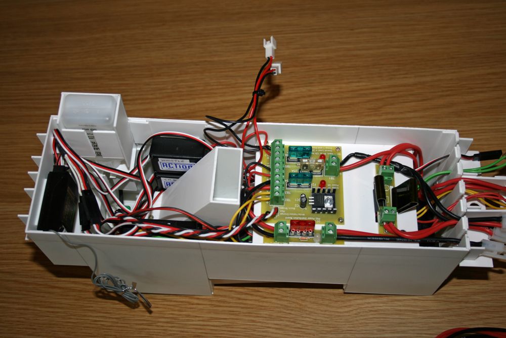
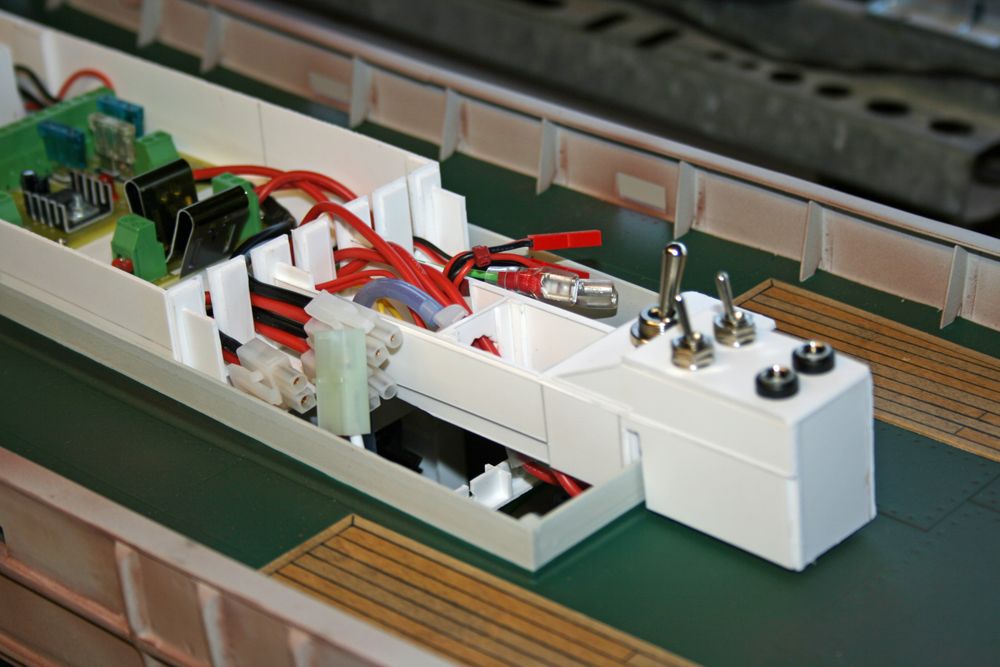
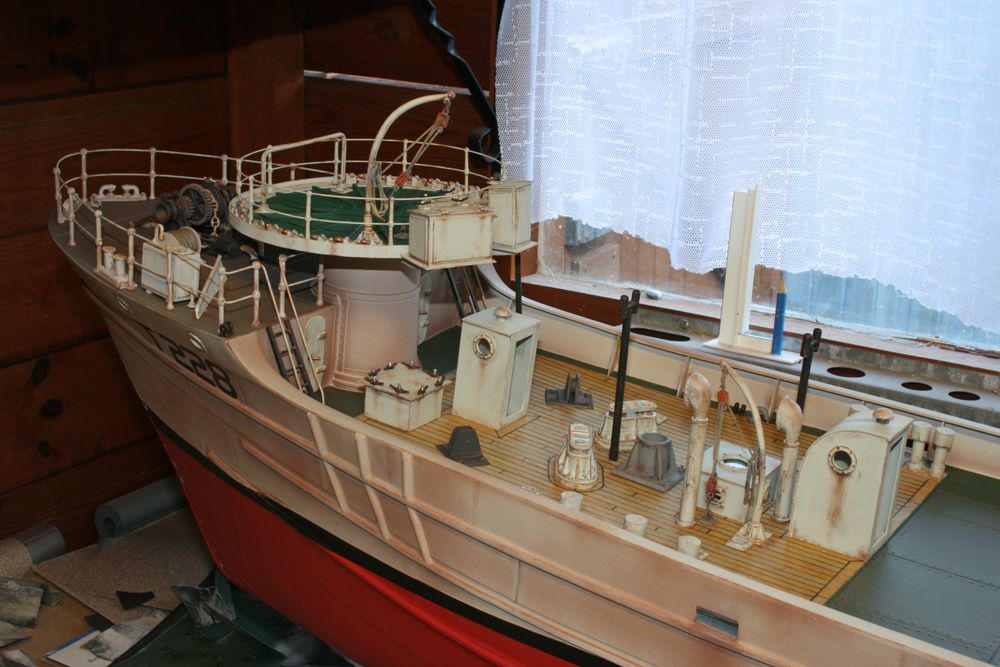


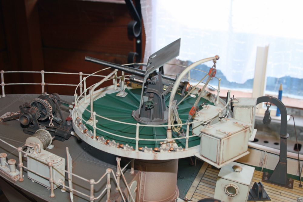
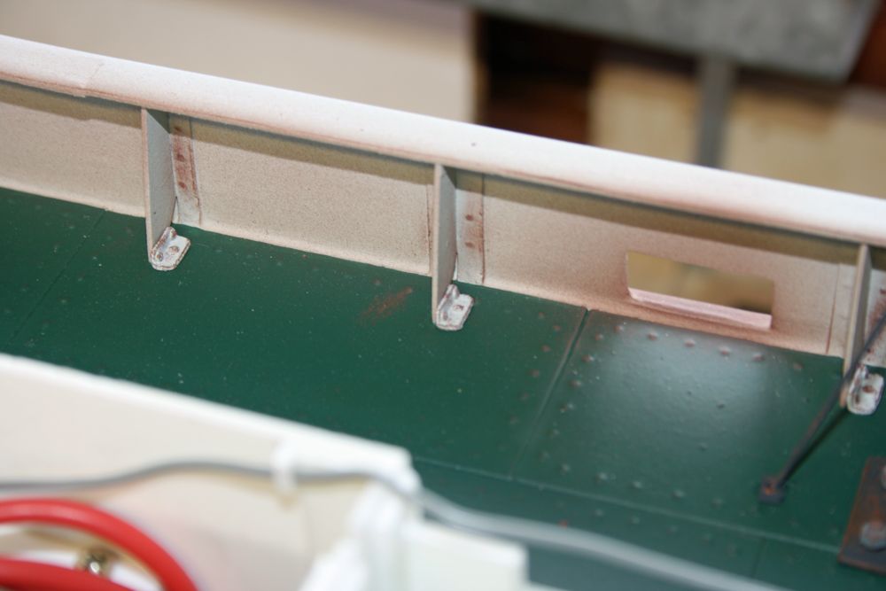


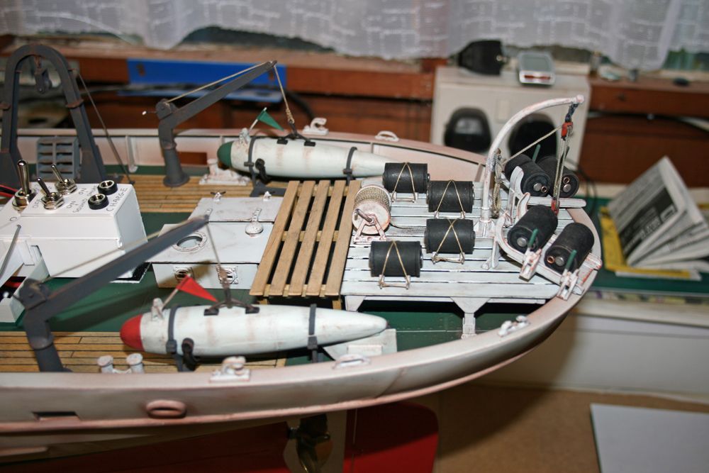
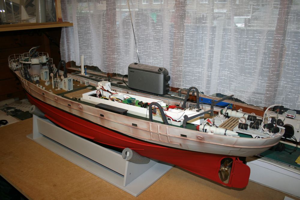
 Hi paul what you have done is first class keep up the good work im just waiting to get my own boat back as a friend is putting lights on it for me will have to have lessons to do it myself.

Code of conduct | Forum Help/FAQs
Latest Replies
-
- Topic
- Voices
- Last Post
-
-
Vic Smeed’s Legacy
Started by:
 Colin Bishop
in: All things floating
Colin Bishop
in: All things floating
- 2
-
6 hours, 30 minutes ago
 Tony Hadley
-
4D Modelshop
Started by:
Keith Long in: Scratch build
- 6
-
13 hours, 7 minutes ago
Colin Bishop
-
Fairey Huntsman 31
1
2
…
5
6
Started by:
 Chris Fellows
in: Build Blogs
Chris Fellows
in: Build Blogs
- 14
-
1 day, 10 hours ago
Chris Fellows
-
Fairey Faun
1
2
3
Started by:
Chris Fellows
in: Build Blogs
- 7
-
1 day, 10 hours ago
Chris Fellows
-
Vic Smeed’s Silver Mist
1
2
…
32
33
Started by:
Bob Abell 2 in: Scratch build
- 4
-
1 day, 11 hours ago
Tony Hadley
-
Fairey Huntsman 28
1
2
…
7
8
Started by:
Chris Fellows
in: Build Blogs
- 1
-
1 day, 12 hours ago
Chris Fellows
-
Eezebilt RAF Fire Boat
Started by:
Tim Cooper in: Build Blogs
- 2
-
1 day, 13 hours ago
 Dave Reed
-
Feathered Friends
Started by:
Chris Fellows
in: Soapbox
- 3
-
1 day, 16 hours ago
Chris Fellows
-
John Cobb’s Crusader
1
2
…
7
8
Started by:
 Paul T
in: Scratch build
Paul T
in: Scratch build
- 1
-
2 days, 12 hours ago
 John W E
-
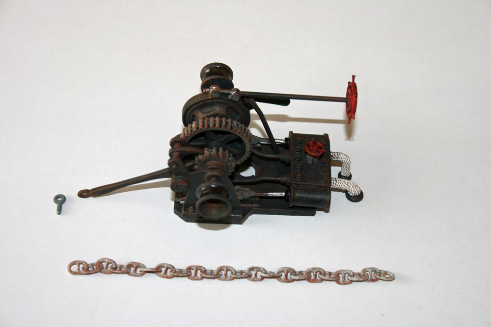
Complex Automata
Started by:
Colin Bishop
in: Soapbox
- 1
-
3 days, 15 hours ago
Colin Bishop
-
RAF Fireboat ID
Started by:
Dave Reed
in: Collectors’ corner
- 8
-
4 days, 16 hours ago
-
TID steam tug 42″ – PN Thomas drawing enlarged
1
2
Started by:
 Ray Wood 3
in: Scratch build
Ray Wood 3
in: Scratch build
- 8
-
5 days, 10 hours ago
 Richard Simpson
-
Lady of Skye (puffer)
1
2
Started by:
 mick east
in: Build Blogs
mick east
in: Build Blogs
- 9
-
5 days, 20 hours ago
Richard Simpson
-
Building a hull.
Started by:
mick east
in: Scratch build
- 7
-
1 week ago
Ray Wood 3
-
Todays Boating
1
2
…
210
211
Started by:
 ashley needham
in: All things floating
ashley needham
in: All things floating
- 84
-
1 week, 1 day ago
Colin Bishop
-
Sea Rover Restoration
Started by:
harry smith 1 in: Collectors’ corner
- 4
-
1 week, 1 day ago
Richard Simpson
-
WORKSHOP LIGHTING
Started by:
John W E
in: All things floating
- 9
-
1 week, 2 days ago
Colin Bishop
-
Mayhem Website Down
Started by:
Colin Bishop
in: All things floating
- 4
-
1 week, 5 days ago
Colin Bishop
-
MAGGIE M trawler
Started by:
 sammyk
in: Buy/Sell or Trade
sammyk
in: Buy/Sell or Trade
- 2
-
1 week, 5 days ago
sammyk
-
meter
Started by:
 Alasdair Allan
in: All things floating
Alasdair Allan
in: All things floating
- 5
-
2 weeks ago
Chris Fellows
-
River Queen 2”- 1’.
Started by:
Richard B in: Steam powered models
- 5
-
2 weeks, 1 day ago
-
Deluxe Superphatic Glue.
Started by:
Colin Bishop
in: All things floating
- 4
-
2 weeks, 1 day ago
Chris Fellows
-
How to add photos to your posts
Started by:
Colin Bishop
in: Adding Images to Forum Posts
- 3
-
2 weeks, 1 day ago
Len Morris 2
-
Cataract
Started by:
Bob Wilson in: Soapbox
- 2
-
2 weeks, 2 days ago
Colin Bishop
-
The mighty tug Wattle
1
2
3
Started by:
mick east
in: Build Blogs
- 10
-
2 weeks, 2 days ago
Richard Simpson
-
Vic Smeed’s Legacy


