Sir Lancelot

Advert

Sir Lancelot

Home Forums Building Kits Sir Lancelot

  • This topic is empty.
Viewing 25 posts - 1 through 25 (of 167 total)
  • Author
    Posts
  • #5992
    Paul Godfrey
    Participant
      @paulgodfrey14946

      Build Log

      Advert
      #21373
      Paul Godfrey
      Participant
        @paulgodfrey14946
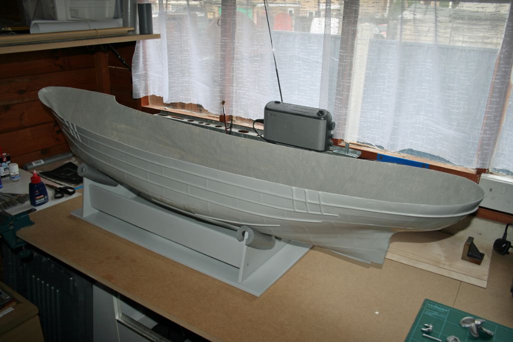
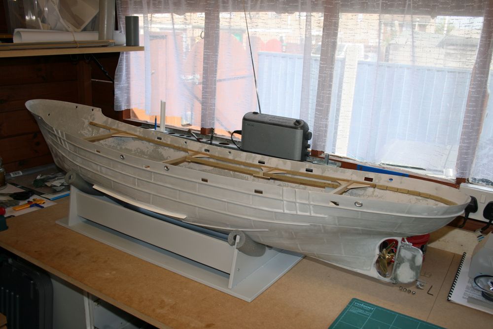
        Just about ready to start the build of Mountfleet’s Sir Lancelot. Progress will initially be quite slow due to other commitments & forthcomming holiday. Here’s a photo of the as yet untouched hull on the newly built stand:
         

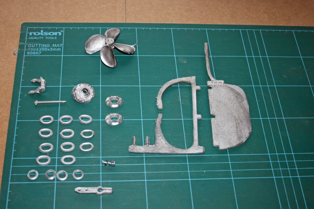
        …and here’s the contents of the first bag of white metal components to be used. Note: the propellor will be replaced by a nice shiny brass item!
         

        Next stage: file, fill, & sand the hull, smooth the inner bulwarks, fit propshaft, rudder frame & rudder, and deck supports.

        Edited By Paul Godfrey on 08/06/2009 18:27:34

        #21461
        Barry Foote
        Participant
          @barryfoote68385

          She makes up into a great model. Original design was by the late Frank Hinchliffe, who started up Caldercraft Models..

          #22369
          Paul Godfrey
          Participant
            @paulgodfrey14946
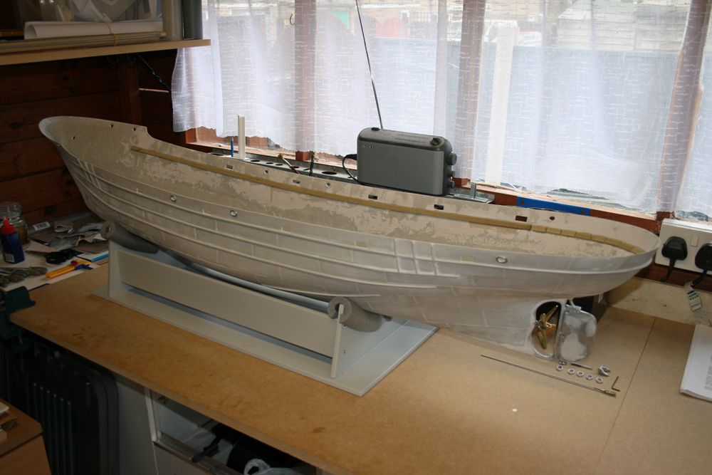
            Two months gone, and some more pictures of progress to date. The first shows the hull with initial cleaning-up done, ports cut out, etc.
             

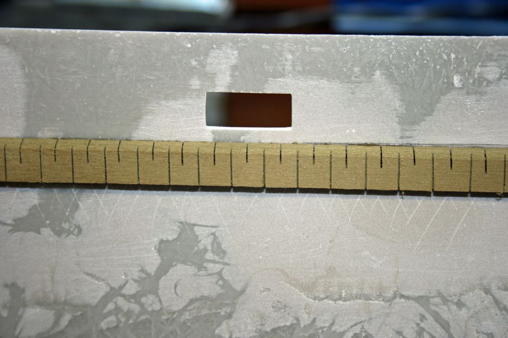
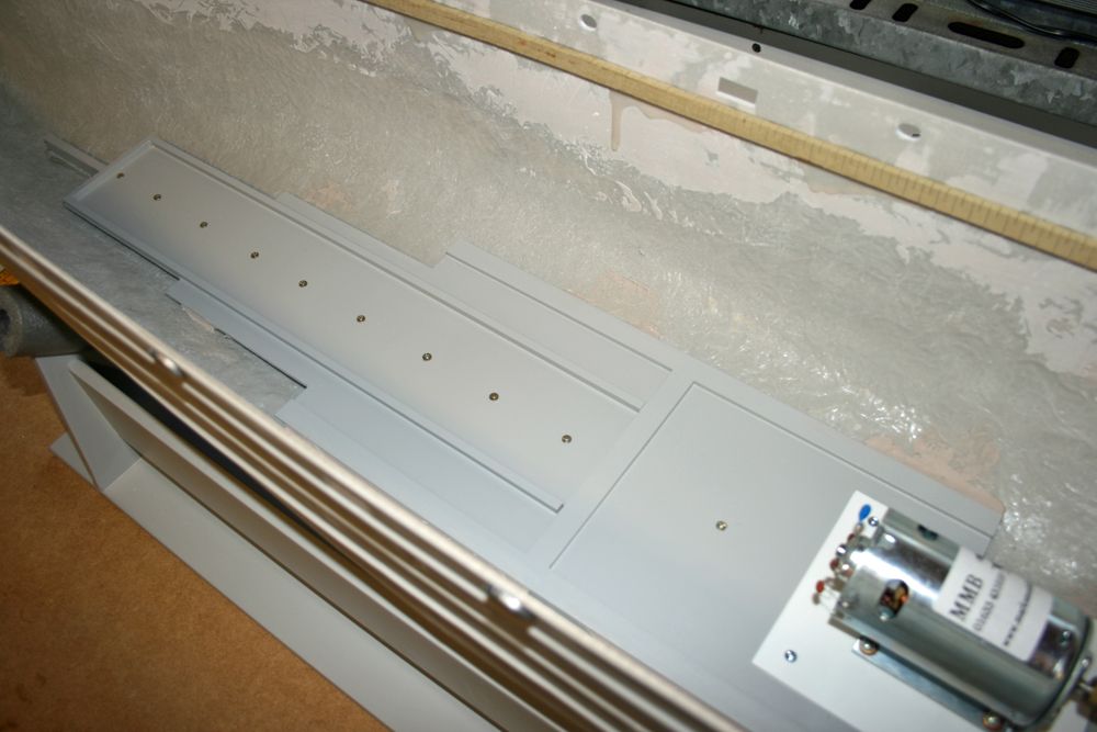
            Here is a close-up of a deck support strip, showing cuts I made to make bending and curving it that much easier. Something I did on my Dutch Courage was to sand, fill, and sand smooth the inner bulwarks BEFORE fitting the deck support strips, and as this worked well, I’ve done it here also. It does make sanding the P38 easier, and it’s then just a case of scoring the area to which the strip is glued. Note that the instructions said to mark the hull for the deck support strip 32mm from the top edge – this would have been some 7mm too low!!
             

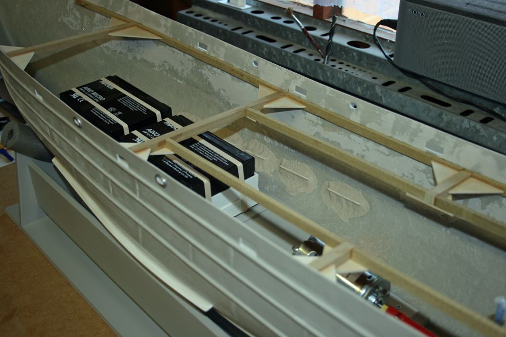
            The next shows the baseboard, made by measuring the available width at points along the bottom of the hull, to keep it as flat as possible. Note the 3/4 x 1/2 wooden bearer bonded to the centre line of the hull, to which the baseboard is attached, and also the long thinner section at the bow, onto which trays containing the batteries & lead weight can be lowered through the deck opening & slid forwards (as access to this area will be very limited once the deck is fitted).
             

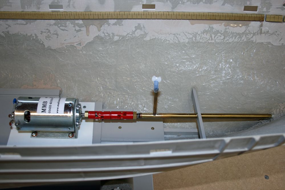
            Here’s the motor & propshaft etc, including oiling tube.
             

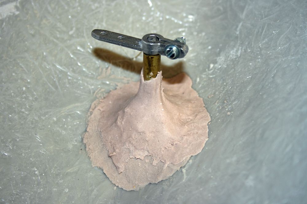
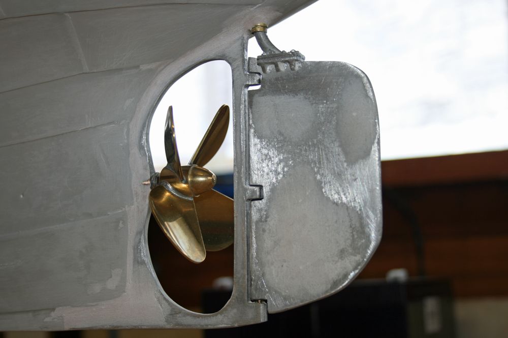
             And lastly, the prop, rudder and tiller. Referring back to photo 2 in this thread showing the unfitted rudder, rather than just have the vertical rod pass through a section of captive brass tube as per the instructions, I first glued a thinner piece of brass tube over this rod, which in turn snuggly fits inside a larger diameter piece of tube bonded to the hull. For me, this just gives it somewhat more strength as I could imaging the rudder vertical rod bending/twisting.
             

             Look closely, and you can just see the two brass tubes in the next pic.
             

            Next will be the rest of the deck supports, the keels, and the battery containers.

            Edited By Paul Godfrey on 02/08/2009 16:54:26

            #22371
            ashley needham
            Participant
              @ashleyneedham69188
              Paul, thats a nice long torqy looking motor wot I dont recognise, what is it   and whats the spec, amps/voltage etc please, cheers  
              Ashley
              #22388
              Barry Foote
              Participant
                @barryfoote68385
                Ashley that motor is one of MMB’s model 900
                 
                 High torque, low RPM 12 pole motor 

                12 volt supply 
                Approx. 3200 RPM on 12 volts 
                Approx. 0.7 amps no load current. 

                Approx. 1 to 2 amps under load (depending on prop size) 


                Barry 
                #22415
                Paul Godfrey
                Participant
                  @paulgodfrey14946
                  I’m glad you answered Ashley’s question Barry, as I didn’t know the specs!!
                   
                  These are  Dave Milbourn’s (who designed my wiring diagram for me) comments regarding this recommended motor:
                   
                  The motor shown is around £30 and is absolutely ideal for this model and prop BUT it is too fast on 12v. Fortunately our P93 Multicontroller can be set to give 50% (i.e. like 6v) output from a 12v input – you just set a couple of switches in the unit to a given position and away you go.
                   
                  Paul
                  #22420
                  Barry Foote
                  Participant
                    @barryfoote68385
                    Paul,
                     
                    Dave must be supplying MMB’s motors….Not surprising really. As for the rest of dave’s gear, it really is excellent and you couldn’t meet a friendlier and more helpful chap. Mind you watch out for his sense of humour!!!!! 
                    #22800
                    Paul Godfrey
                    Participant
                      @paulgodfrey14946
                      A little more progress made. Here’s the hull as it is now:
                       

                      The remainder of the main deck supports have now been fitted, together with various strengthening pieces, as shown below.
                       

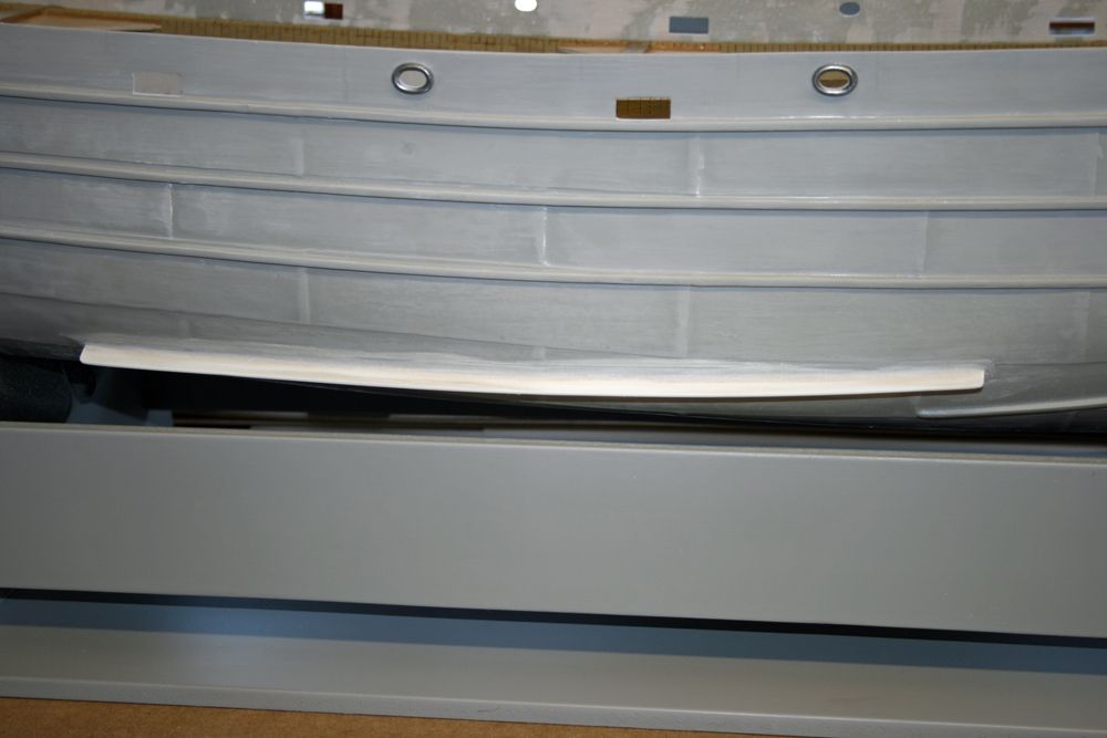
                      The central cross-beam just above the motor was cut out only when the whole support structure for the main deck had thoroughly dried. The next photo shows one of the bilge keels, which I decided to make from plasticard rather than ply. I did not like the idea of a piece of wood, constantly in the water, and only held on by a few pins and a thin strip of wood above and below the joint to the hull. I instead made the keel with five ‘tongues’ which fit inside five slots made in the hull, and once the expoxy had dried, packed the tongues all around with P38 filler.
                       

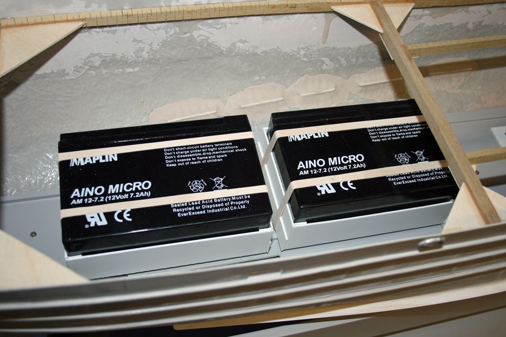
                       The keel ‘tongues’ can be seen in the next photo, along with the two battery boxes made from plasticard. As mentioned earlier in this log, the boxes can be slid along on ‘rails’ to get them under the main deck, and to allow easy removal. How far forward they are allowed to slide will be determined by the eventual ballasting of the boat.
                       

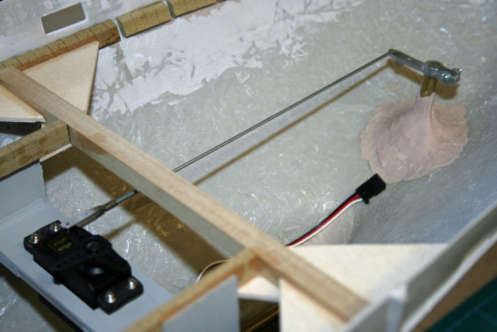
                       And finally for this installment, the rudder servo and linkage.
                       

                      My next task will be to construct a plasticard ‘tray’ for all the electronics, which will fit in the deck opening, beneath the superstructure. This tray will utilise as much space as possible (width, length & depth), and apart from the electronics, will also house the smoke generator. It will be easily removable for access to the batteries, motor etc. All will become clearer – watch this space!
                       

                      #22807
                      Barry Foote
                      Participant
                        @barryfoote68385

                        Coming along very nicely……I am enjoying this thread..

                        #22816
                        Paul Godfrey
                        Participant
                          @paulgodfrey14946
                          Thanks Barry, appreciate your comments, and I’m glad you’re enjoying it.
                           
                          I’m trying to describe what I do in as much detail as possible, especially any problems I encounter (due either to my inexperience, or the kit itself), and the solutions I come up with. This way, other beginners, or people thinking of building this kit, can get an insight into what’s involved.
                           
                          Hope you’re a patient man, Barry, as this build may take some time!
                           
                          Regards, Paul.
                          #22865
                          Bob Abell 2
                          Participant
                            @bobabell2
                            Considering this is only your second model, you are making an excellent job of it at every stage
                             
                            Take your time, Paul………..You don`t want to finish it, in the cold weather!
                             
                            Bob
                            #22880
                            Paul Godfrey
                            Participant
                              @paulgodfrey14946
                              Thanks for your comments Bob.
                               
                              I’ll time it’s completion for the spring. . . . . . . .2012!!!
                               
                              Paul
                              #23073
                              Paul Godfrey
                              Participant
                                @paulgodfrey14946
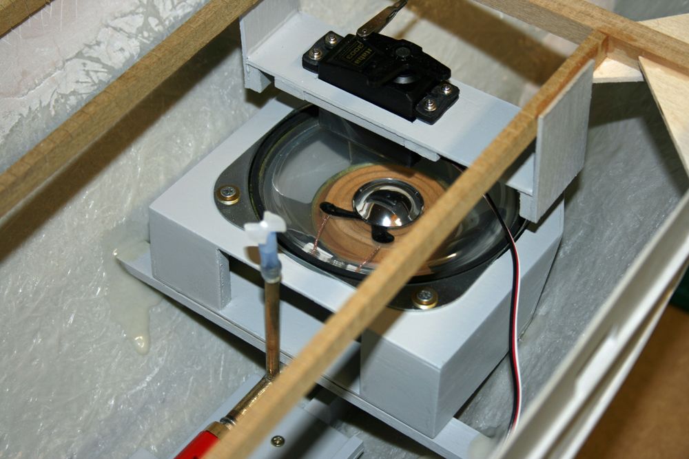
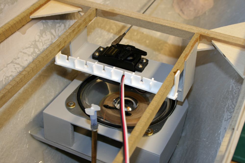
                                I do like to have good access to the components used in the build of any radio control model – there’s nothing worse than having something fail that you can’t get to without hacking things about to gain access. This very much applies, of course, to Sir Lancelot. Unlike my Dutch Courage, which has super access to all the ‘gubbins’, Sir Lancelot is at the other end of the scale, and this has caused a lot of head scratching!. I’ve already discussed the way that the batteries can be installed/removed, and the next thing to think about was the speaker. In the end, I built a box from liteply, angled at one end to allow the following installation:
                                 

                                This has been glued to the propshaft tube support seen in previous photos, and a new cross-beam seen just behind the oiling tube in the above photo. The screws which attach the speaker to the box are easily accessible, and removal (should it ever be needed) is straightforward after the rudder servo has been lifted out. The opening at the front end of the box allows the wires to be easily attached.
                                 
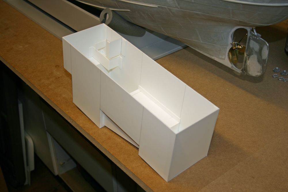
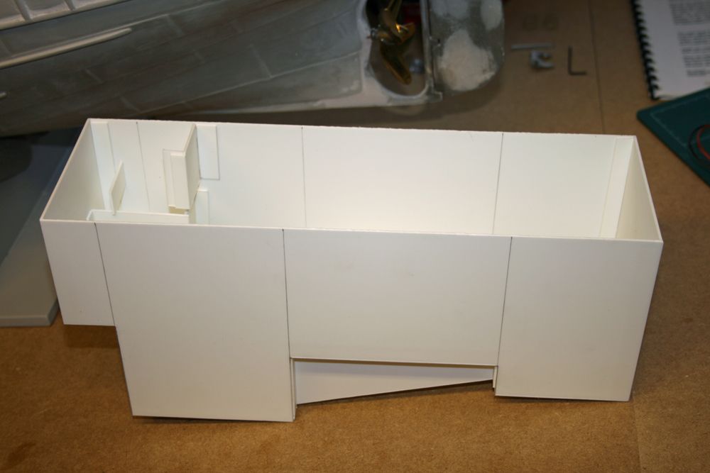
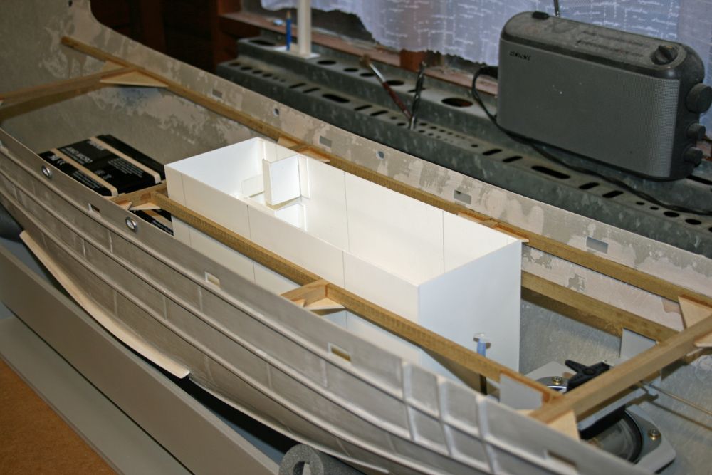
                                I have also now built the electronics ‘tray’ as mentioned in my last installment, and the next two photos show it in it’s basic form:
                                 

                                Referring to the second photo, you can see that there are 4 sections seperated by the pencil lines. From left to right, the first allows clearance of the rear-most of the two 12v batteries; the second utilises the full depth available and will house, amongst other things, the smoke system (see next pics), the next section is raised to clear the motor (the two angled supports go either side of the motor), and finally the last section sits just above the propshaft couplings. As you can see, plenty of space for all the electronics – further internal dividers (like p.c. boards), possibly shelves, will eventually be incorporated to house the components, and these of course will all be removable.
                                 
                                Slots/holes will be made in the rear end of the tray, and it will be here that all of the connectors required to allow easy removal of the tray will reside. These are:
                                 
                                1) The rudder Servo lead,
                                2) The wires to the batteries,
                                3) The motor wires,
                                4) The speaker wires,
                                5) The two lighting circuits.
                                 
                                More of this at a later stage. Here’s a photo of the tray resting in the deck opening:
                                 

                                It will, in due course, be attached to blocks bonded to the coamings (and yes, I have allowed for the thickness of the coamings when measuring the width of the tray!!), and will therefore be suspended just above the battery, motor & coupling.
                                 
                                Next is the smoker housing.

                                #23074
                                Paul Godfrey
                                Participant
                                  @paulgodfrey14946
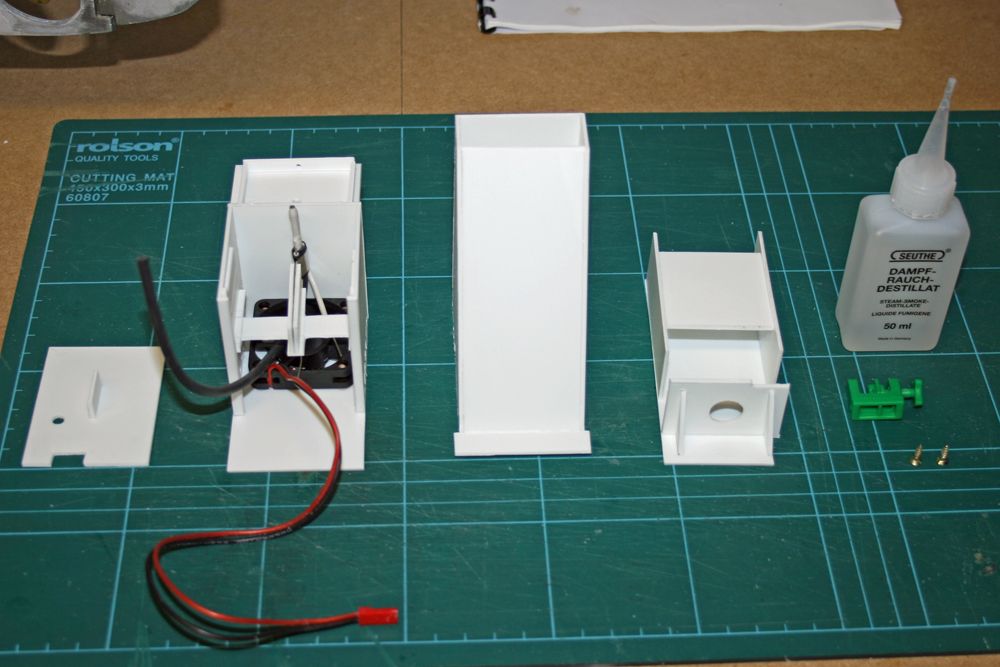
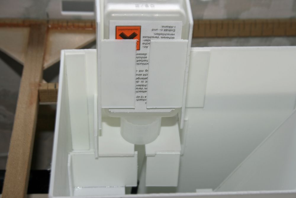
                                  This photo shows the components of the smoker housing I have designed:
                                   

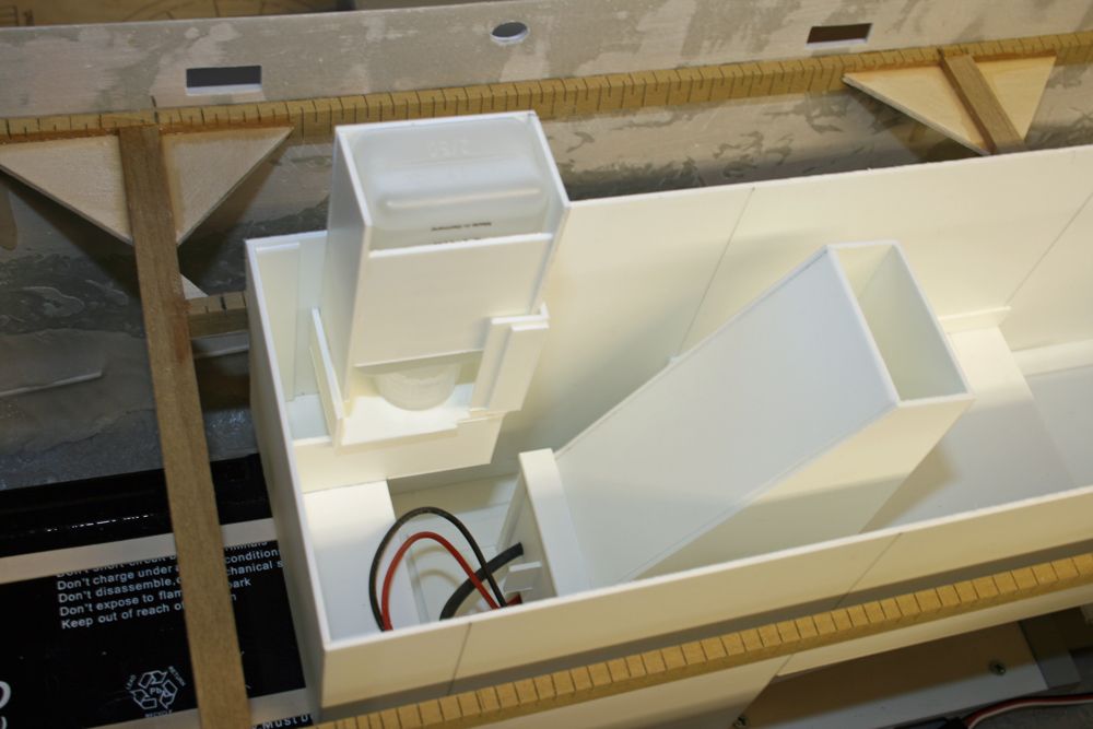
                                  The unit second from the left is basically a box, with 4 short lengths of brass tube bonded to the base onto which the fan fits. The smoker element sits in a slot above, and of course, both items can be easily removed. On the left of the photo is the front door, which slides down channels on either side, with a hole for the smoke oil tube, and a cut-out at the bottom for the wiring. The tall unit in the middle sits on top of the fan housing, and eventually will be extended higher by plastic tube once the exact position of the funnel has been established. The oil container on the far right fits into the unit to the left of it, and this in turn slots into a housing built into the electronics tray, as can be seen in the final photo for this installment:
                                   

                                  The lower fan/smoker element housing is attached by a single screw, and the upper extension is screwed to this. When changing the oil container, this and the fan/smoker housing can be removed together without disconnecting the oil pipe, making this task easier (and less messy).
                                   
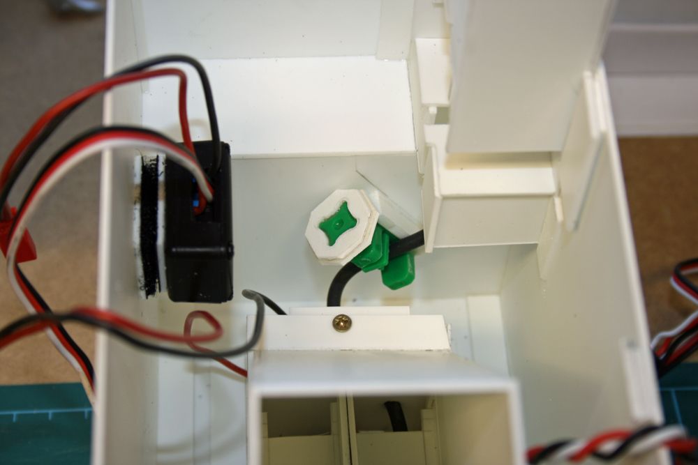
                                  You will also see a small green item in the photo of the individual components, this is the oil pipe shut-off valve, and what I want to avoid is to have to remove the superstructure just to open or close this valve.  I will therefore bond this valve to the vertical partition just below the oil container nozzle, at such an angle that by inserting a long allen key (or small square-section rod) through a small hole in the side of the superstructure, it will slide into a section of square-section brass tube which has been bonded to the valve ‘handle’.
                                   
                                  That’s all for now. Not sure at this stage whether to continue fitting out the tray with all the gizmo’s (I do have everything except the new steam sound unit which Mr Milbourn is currently designing – that’s why my wiring diagram on Action’s web site doesn’t have this included!), or maybe fit the main deck. 
                                   
                                  Paul.

                                  Edited By Paul Godfrey on 09/09/2009 21:53:59

                                  Edited By Paul Godfrey on 09/09/2009 22:01:13

                                  #23076
                                  neil hp
                                  Participant
                                    @neilhp
                                    any chance of you doing a drawing and plan of the unit, paul for publication………..it looks very interesting, not only for your vessel but for others as well.
                                    neil.
                                    #23096
                                    Paul Godfrey
                                    Participant
                                      @paulgodfrey14946
                                      Hi Neil,
                                       
                                      Leave it with me – I’ll break out the ruler & pencils!! I don’t have a C.A.D. program unfortunately, so my drawings will have to do!
                                       
                                      Regards, Paul.
                                      #23105
                                      Paul Godfrey
                                      Participant
                                        @paulgodfrey14946
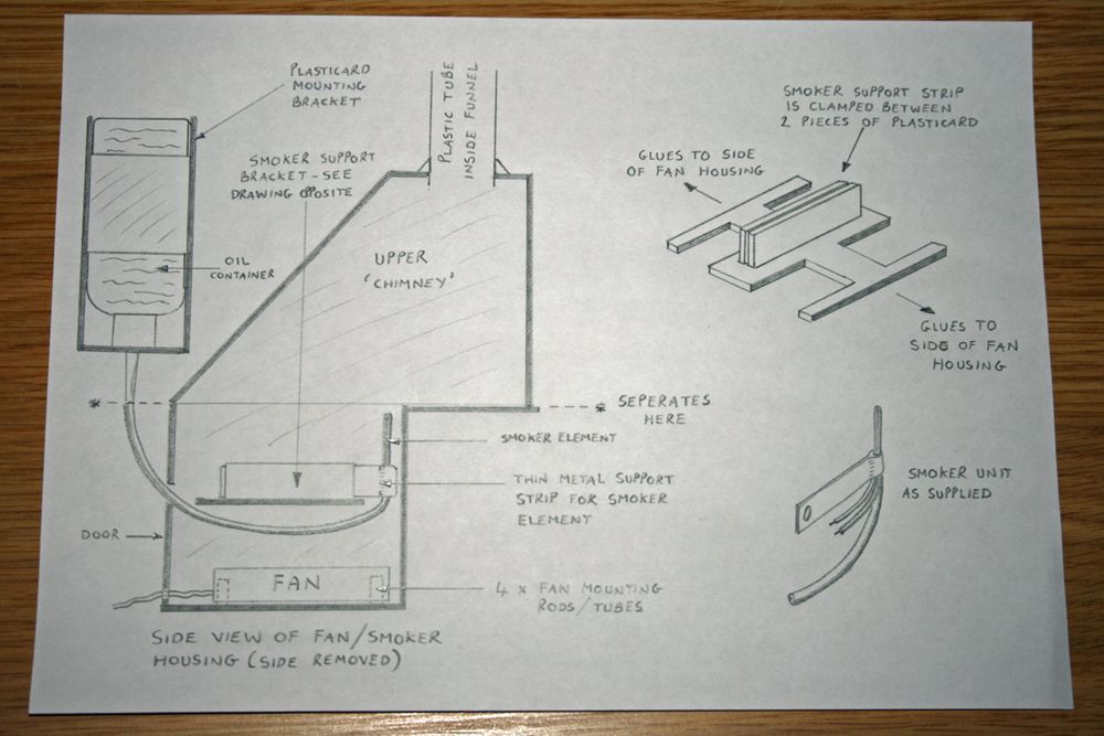
                                        As you will see, my drawings are not exactly top-notch, but I hope they show the smoker unit in adequate detail. I have not included measurements, as each boat will be different, but I first built the fan & smoker housing base using the fan dimensions as a guide. The height of the housing was governed by the smoker ‘element’ being sufficiently spaced above the fan to allow the fan to be lifted off its four corner mounts, should the need arise due to malfunction etc. The top of the housing is roughly level with the smoker element. The ‘door’ at the front can, as previously mentioned, be lifted up (after the angular ‘chimney’ has been detached from the housing), allowing access to both the fan & the smoker. The drawing shows the smoker support which is glued between the housing sides, and consists of a ‘HH’ shaped piece of plasticard (so shaped to allow a good flow of air from the fan), down the middle of which are glued two pieces of plasticard virtually side-by-side. The metal support strip of the smoker can then be squeezed between these two pieces of plasticard to hold it firmly in place.
                                         

                                        The smoker, fan (and fan speed controller) were obtained from Action Electronics.

                                        As with all the photos in this thread, click on them for a larger image – you’ll need to with these sketches!!
                                         
                                        Paul.
                                         
                                        #23108
                                        neil hp
                                        Participant
                                          @neilhp
                                          thanks for those paul. they are a great help for when i come to build mine.
                                          cheers, neil.
                                          #23109
                                          Dave Milbourn
                                          Participant
                                            @davemilbourn48782
                                            Paul
                                            You’ll get a better sound from the speaker if you fully enclose the box at the back of it. The idea is to prevent the air being pushed from the underneath of the speaker from meeting the air being pushed from the top (hope that’s clear enough!).
                                            A tube around the front to duct the sound upwards and stop it spreading sideways (in simple terms) can also enhance the sound.
                                            I like the box, and I want some piccies of the finished article and installation for our website Rogue’s Gallery – that’s if I ever get time to compile it!
                                            Dave M
                                            #23128
                                            Paul Godfrey
                                            Participant
                                              @paulgodfrey14946
                                              Neil,
                                               
                                              You’re very welcome. I forgot you have a Sir Lancelot to build (it’s an age thing), so if you want measurements for anything I have done, you only have to ask. I have made a slight improvement to the oil bottle holder. In the photo of the individual smoker housing components, and the drawing, the oil bottle is slotted in to a plasticard ‘cage’ made up of a back, sides, and a smaller front piece, together with a bottom piece with a hole in it, into which the nozzle fits. Previously, this unit then slotted into another bracket attached to the side of the tray. Now though,  the bracket has been removed, and the cage has been itself glued to the side of the tray. To allow the bottle to be lifted out with the feed tube still attached, I have cut a vertical slot in the front of the cage, and a slot in the bottom where the nozzle fits into the hole. Here’s a photo:
                                               

                                              So, to remove the oil bottle and the smoker housing, I remove the chimney, then lift the smoker housing up at the same time as the oil bottle, directing the feed tube through the slots I’ve now cut.
                                               
                                              Dave,
                                               
                                              The speaker box I’ve made does have a back – the photo’s flash has caused a shadow and perhaps given the impression it doesn’t. The only opening is at the front end for the wires. The box is now well and truly glued into place, but there will be some more photos of hull interior once I’ve put in the electronics, prior to the deck being fitted. Thanks for the tip regarding the ducting tube – I’ll make this addition in due course.
                                               
                                              Cheers, Paul
                                              #23211
                                              Paul Godfrey
                                              Participant
                                                @paulgodfrey14946
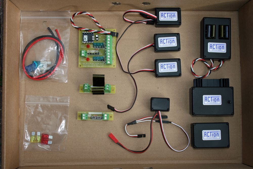
                                                I’ve now completed as much of the electronics tray as I’m going to for now, all of the components (except for the receiver and steam engine sound module) have been fitted, and it just remains for these two items to be fitted, along with the wiring. These are the items used (minus the fan which has already been fitted as per the previous updates):
                                                 

                                                Not including the bags, the item top-left is the Power Distribution Board, below that is the Schottky Diode Board, and the Single Fuse Board. To the right of the P.D.B.are the three Single Relay Switches (one each for the two lighting circuits, and the other for the amplifier), and below these is the fan controller. Top right is the Multi Controller, beneath is the Audio Mixer/Booster, and finally the Steam Whistle/Horn unit.
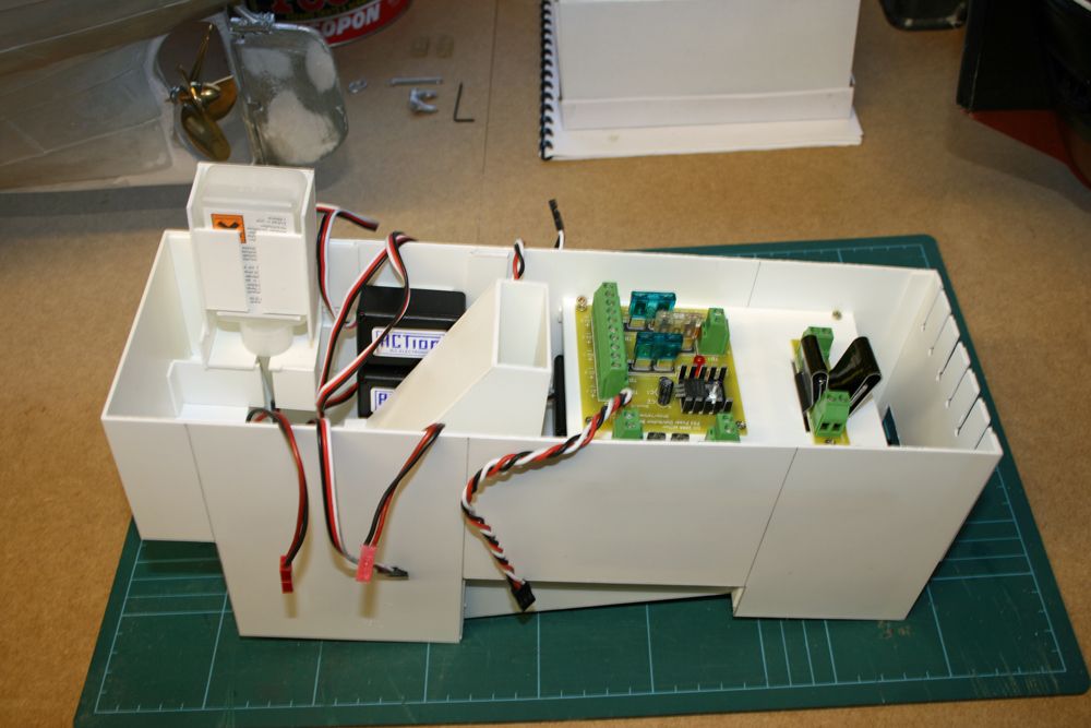
                                                The next photo shows the items fitted to the tray:
                                                 

                                                #23213
                                                Paul Godfrey
                                                Participant
                                                  @paulgodfrey14946
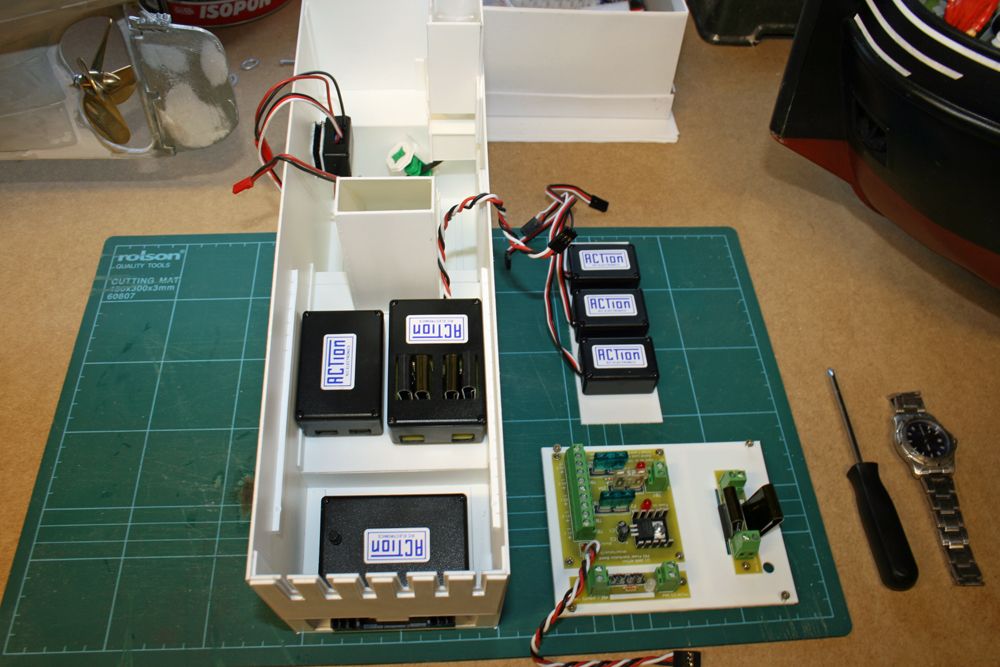
                                                  The three switches are attached with double-sided tape to a plasticard strip, which is slid down between two channels into place. The three circuit boards are attached to a removable ‘shelf’, with other components below this attached with velcro. The fan controller is attached to the side opposite the smoker oil, also with velcro. The receiver will be attached to the inside of the front section, adjacent to the oil container, and there is ample space for the steam engine sound unit. The next photo shows the circuit board and switches removed:
                                                   

                                                  With the shelf removed, access to the other components is easy. The amplifier is fitted to the lower rear section of the tray, with a cut-out allowing the heat-sink a good amount of clearance. Above this you will see that slots have been cut into the rear section of the tray. These allow the various wires to exit the tray, with connections being on the outside of the tray. A slotted strip has been made, and bonded across the deck opening near the servo, and this will hold the wires and connectors that join to the wires exiting the tray. So, when removal of the tray is required, the various wires (to the batteries, motors, speaker etc) can be disconnected, and the ends wont drop down into the hull – instead, they will remain in their correct positions allowing easy re-connection.
                                                   

                                                  The next photo shows the oil cut-off valve positioned, but not yet bonded in place. As previously mentioned, I want to be able to open and close this without removing the superstructure, so have devised a mount made from plastic into which the valve has first been bonded. Two plasticard ‘discs’ have been made, and glued around the valve handle, and eventually a short length of square-section tube will be bonded into another disc which will then be glued onto the front of the handle. This tube will, as mentioned before, allow the handle to be turned by a long thin allen key, inserted through a hole in the superstructure side (a plastic tube will be fitted between the side of the tray and the valve, allowing the allen key to find the square-section tube easily). Does all that make sense?!! Here’s a photo:
                                                   

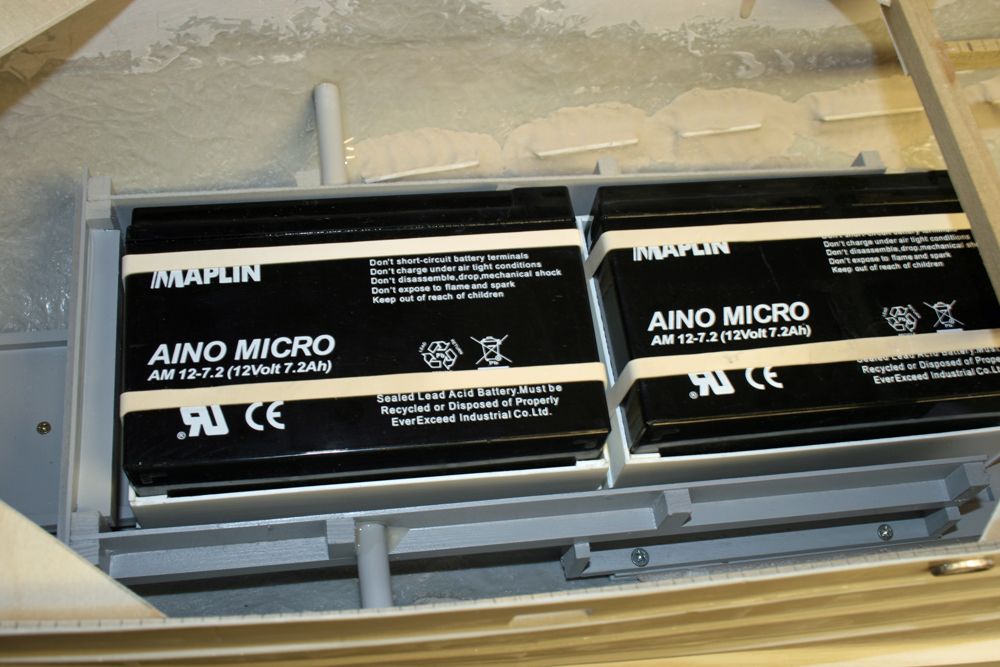
                                                  I have also now fitted a ‘cage’ around the batteries, which will prevent them from moving any further forward (I really cant see the need now to have them move any further forward for ballasting reasons), and will also stop them from moving left or right in the unlikely event that they are thrown off their ‘rails’. The cage is made from lite ply, and strengthened with strip wood, giving a light yet strong structure. It has been attached to the baseboard with glue and screws, and there are two side supports for added strength:
                                                   

                                                  The front battery will have a strap around it length-ways, to be used to pull it out when removal is required. There is sufficient room down the right side for the wiring.
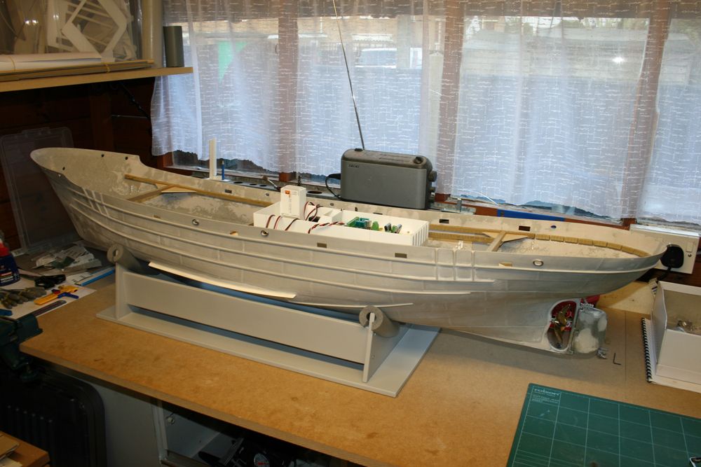
                                                  The final picture shows the whole boat as it is now.
                                                   
                                                   
                                                  Thats all for now.  Paul

                                                  Edited By Paul Godfrey on 20/09/2009 20:14:42

                                                  #23244
                                                  Barry Foote
                                                  Participant
                                                    @barryfoote68385

                                                    Paul,

                                                    Your installation is far too neat and tidy for us mere mortals!!!! A real credit to you. Those ACTion products really are top notch.
                                                    A cracking job so far…..keep it up.
                                                    #23259
                                                    Paul Godfrey
                                                    Participant
                                                      @paulgodfrey14946
                                                      Many thanks, once again, for your comments Barry.
                                                       
                                                      It all seems to be going ok at the moment, a major c**k-up MUST be on the cards soon!!
                                                       
                                                      Paul
                                                    Viewing 25 posts - 1 through 25 (of 167 total)
                                                    • Please log in to reply to this topic. Registering is free and easy using the links on the menu at the top of this page.

                                                    Code of conduct | Forum Help/FAQs

                                                    Advert

                                                    Latest Replies

                                                    Home Forums Building Kits Topics

                                                    Viewing 25 topics - 1 through 25 (of 25 total)
                                                    Viewing 25 topics - 1 through 25 (of 25 total)

                                                    View full reply list.

                                                    Advert

                                                    Newsletter Sign-up