Another billings slo-mo-shun

Advert

Another billings slo-mo-shun

Home Forums Building Kits Another billings slo-mo-shun

  • This topic is empty.
Viewing 25 posts - 26 through 50 (of 177 total)
  • Author
    Posts
  • #26141
    Phil Winks 1
    Participant
      @philwinks1
      Cheers Bob.
      The order of planking top/bottom is in my head, some of the other threads elsewhere have discussed this too.
      The consensus seems to be 3 or 4 planks on top to help stiffen the frames then turn over, and skin the bottom and seal inside.
      Then finish the top off.
      However this still leaves the inside of the top to seal in a very confined  space. Mind you, you’ll get that issue whichever way.
      So I guess it’s a question of which is easier to get at through the Hatch? hopefully you have an answer to that one!!!


      Phil
      Advert
      #26142
      Bob Abell 2
      Participant
        @bobabell2
        Hello Phil
         
        It`s amazing how far back the info was……( Page 33 )
         
        Basic hull………………………………19 lb
         
        Four batteries…………………………..7 lb
         
        Total weight……………………………26 lb
         
        Motor MMB900………………… power……………………360 watts each
         
        Now it`s confession time!………The motors are 4″ apart………….The fans are 4″ dia
        Yes!…………………….You`ve guessed it!………..They`ve been touching!
         
        So after the next run, I`ll reduce the fan diameter………and get more power!
        #26146
        Phil Winks 1
        Participant
          @philwinks1

          Thanks for that info Bob (reply on your thread).

           
          A few planks fitted today (and I didn’t have to re-arrange my chores either)
           
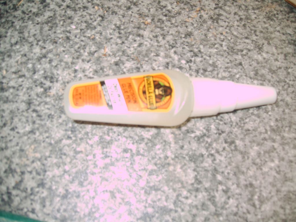
          The glue I’m using is white (faster setting) Gorilla glue. incredibly strong, totally water proof, with a foaming action that ensures it creeps right through the joint. using it is simple enough. You dampen one face, glue the other and cramp it, the tighter the better.this one takes about 30 min to take hold the brown version about an hour. however leave the clamps on longer esp in cooler temps. The moisture is what sets it off. so on a dry day that bit is really important. Clean up while wet is with meths, esp your hands, as once cured it’ll take a week of scrubbing to remove. Excess on the joint is simply carved/sanded off when cured. Finally always clean the nozzle with a cloth dampened with meths, then expel as much air as possible and replace the cap asap.

          Edited By Phil Winks 1 on 28/03/2010 18:59:07

          #26153
          Bob Abell 2
          Participant
            @bobabell2
            Geez!…………….That glue looks a bit heavy!………….and a bit…OTT!
             
            The fun starts, when you get round the bend!
             
             
            Bob
            #26154
            Bob Abell 2
            Participant
              @bobabell2
              If you are not careful, Sunshine……………..I can see the makings of the dreaded Banana Boat effect!
               
              You need to hold the hull DOWN with heavy weights, otherwise, the planks will try and spring up……………..Try strong cord with a weight at the end, fastened at one side of the bench and laid over the planking and off the edge of the bench on the other side……..about fiveor six of `em should do it!
               
              Over `n` out…………………Bob
              #26155
              Phil Winks 1
              Participant
                @philwinks1
                Got that all in mind Bob.
                 
                One advantage of building at this scale is every thing is so thin it bends easily, and if the bottom is skinned before I go round the bend (on the boat lol) everything will be so much stiffer.
                 
                The appearance of the glue being OTT is due to its foaming capability. the stuff you see is also full of air bubbles that’s why its so important the joint is clamped, the tighter the better, within reason. It is very light and what you see there will all be sanded of this evening leaving a hair line joint that’s stronger than the wood itself.
                 
                Phil
                 
                 
                #26157
                Phil Winks 1
                Participant
                  @philwinks1
                  I’ve done a little research on  the power plant and bty’s and to save weight I will need to go the LiPo/brushless route. There really is no comparison.
                   
                  The weights come out as follows
                   
                  Motor    =212g
                  ESC      =   50g
                  bty’s       = any thing from 478g for 4000mah down to 204g for 1800mah
                   
                  so total powertrain weight can be as little as 466g (about 25% of the planed weight) and still del 200w if I put the weight up to 728g I can ask for 388w but that would be on the limits of the esc. (not the best plan)
                   
                  obviously cost is a factor and this little lot will rush me about £80 but that does include spare bty’s (1 set at least)
                   
                  Time to convince the domestic manager to let me at the savings LOL
                   
                  Phil

                  Edited By Phil Winks 1 on 29/03/2010 15:21:00

                  Edited By Phil Winks 1 on 29/03/2010 15:24:20

                  #26158
                  Phil Winks 1
                  Participant
                    @philwinks1
                    Now for some pretty pics of the intended power bits

                    Very blingy but so capable

                    #26160
                    Bob Abell 2
                    Participant
                      @bobabell2
                      That looks the bizz. Phil……..Reasonably inexpensive too!
                       
                      How long is the motor and what`s the diameter?
                       
                      I suppose if you use a very short prop shaft, to save the weight….. the batteries can go in the front end
                       
                      Made any progess today?
                       
                      Bob
                      #26163
                      Phil Winks 1
                      Participant
                        @philwinks1
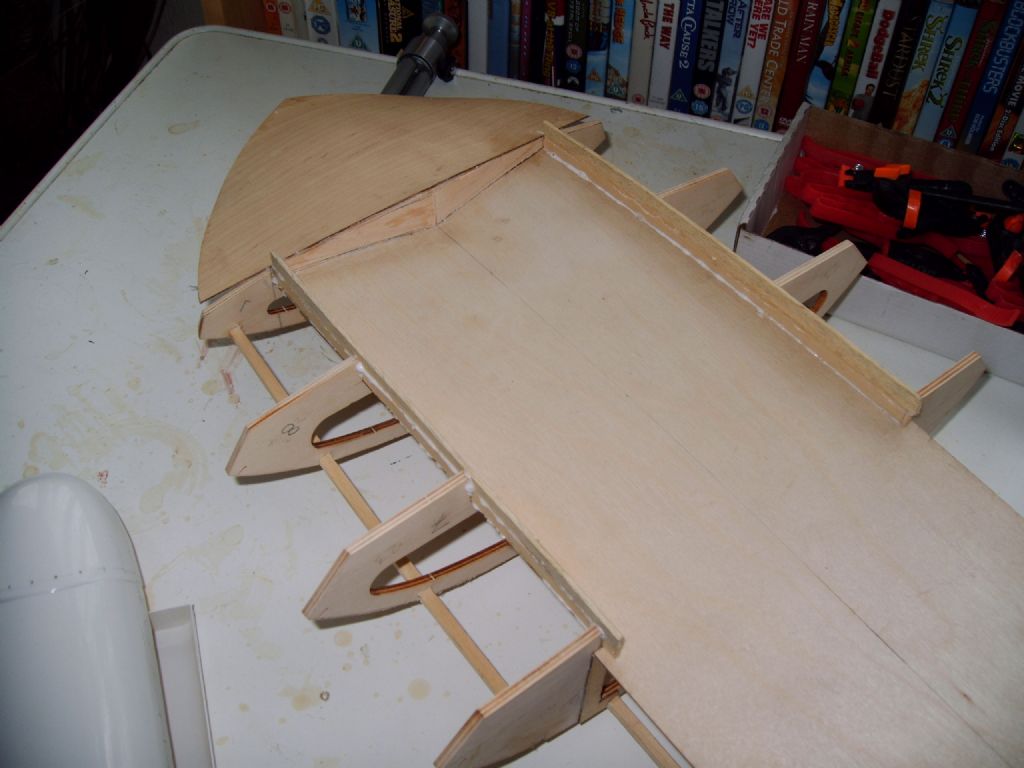
                        Hi Bob! yes a little progress today the jig is off and the bottom skin from stern to the step. here I find a quandry. the triagular filler pieces that form the step are shorter at their outer edges than the front sponson frames they are supposed to fit against
                         
                        see photo’s
                         
                        Skins dry fitted

                        And the other view

                         
                        Now the question must be is one to big or the other too small? this isn’t one I’ve seen mentioned in other build blogs!
                         
                        Looking at the final sponson line there does appear to be a bit (but only a bit) of a hump at this point however building the filler piece up will only serve to have the bottom of the front sect deeply imersed even when on the plane so I think I’ll be shaving a little off the sponson frame to the point where there is a more natural line and see how it goes from there. maybe 1st try reducing the inner end of the sponson frame as the outer line looks good the hump is on the inside line.
                         
                        Phil
                         
                        Another post to follow re other progress and the answers to your questions on the motors Bob

                        #26164
                        Bob Abell 2
                        Participant
                          @bobabell2
                          That`s a nasty one!…………….How about fitting the nose side walls first and using the edge as a sighter………………….Take your time!
                           
                          You`ll also find that fitting the bottom nose piece a bit tricky too because it`s a compound curve………………and ply doesn`t like it!
                           
                          Bob
                          #26165
                          Phil Winks 1
                          Participant
                            @philwinks1
                            Ok while your pondering that one here’s the full details on the motors,ESC & batteries.
                             
                            The motor Stats are
                            Dia 33mm
                            Length 70mm
                            weight 212g
                            Volts 7 to 17
                            Amps 80 continuos
                                        100 max
                            Revs per volt (Kv) 1500
                             
                            ESC stats
                            Dims 48x35x20mm
                            weight 50g
                            current 35A constant
                                           70A burst
                            Input voltage 7.2 to 22.4v ie 5-19 nimh or 2-6 lipo
                            Water cooled
                            Progammable reverse/brake
                             
                            Batteries (most likely choice will be)
                            2250mah 2s1p lipo x 2 in series to allow them to sit in the entrance to either sponson. this gives me a 4s1p bty with a total of 14.4v spinning the motor at a theoretical 21000 rpm from experience it’s more likely to max out somewhere around 19000rpm
                             
                             
                            Finally two bits of progress today 1 the jig came off and the 1st bottom  skin went  on and I’ve made up the P bracket for the propshaft.
                             
                            Hit another problem as well as the one in the previous post above.
                             
                            The prop tube is about 2″ short to reach the 2nd support and still exit the hull.
                            bloody poor show that!


                            Phil
                             
                            #26166
                            Phil Winks 1
                            Participant
                              @philwinks1
                              Hi Bob your right one thing in my favour with the nose skin is it’s not much, if any, of a curve front to back and dry fitting has suggested little problem there especially if I reduce the front sponson frame at the inner end only. the other + this way is when viewed head on the trianglular gap inboard of each sponson will top out above waterline allowing air to rush in as speed increases and presto easy on the plane (I hope)
                               
                              Phil


                              #26193
                              Bob Abell 2
                              Participant
                                @bobabell2
                                Morning, Phil
                                 
                                Little Slo Mo is a little late of date?
                                 
                                Suspect you`re up to summat?
                                 
                                Just being nosey again…………………..Bob
                                #26196
                                Phil Winks 1
                                Participant
                                  @philwinks1
                                  Hi Bob not up to anything well not on Little Slo-Mo anyhow’s.
                                   
                                  The esc for that little speed boat arrived yesterday so spent what little shed time I had installing that ready for a session on sunday. and finishing of a floating dock for the steering course.
                                   
                                  Having taken a rest from the gritty issue of the sponson/fore sect line am now ready to get in there this afternoon and tackle it.
                                   
                                  I’ve spent an hour or two dry fitting all the bits round the area and it really looks like a half and half job. so unless I spot some thing different this afternoon thats the way I’m going
                                   
                                  Phil
                                  #26202
                                  Phil Winks 1
                                  Participant
                                    @philwinks1
                                    The issue is solved (thank goodness)
                                     
                                    It turned out that both the sponson frame and the filler piece both needed altering, at the junction between them but not at, the frame outboard edge, and the filler inboard edge.
                                     
                                    this has resulted in a line that is slightly less curved across the beam and is more in keeping with the appearance of the original
                                     
                                    and makes the tunnel entrance, between the sponsons a little more open to allow air between the sponsons when “on the plane” A good thing!!
                                     
                                     
                                    Here she is still clamped up. Note Bob being made from such thin stuff it’s easier to clamp!!

                                    Fingers crossed for when the clamps come of this evening.


                                    Phil
                                    #26203
                                    Phil Winks 1
                                    Participant
                                      @philwinks1
                                      Further on the motor selection. having gone to a specialist fast electric forum looking for confirmation of my choice I got it plus a sensible suggestion on prop size and what speed to expect. the gent advising used a prog called “FeCalc” to work all this out and the results are promising to say the least
                                       
                                      they are
                                       
                                      { there is a program out there called FeCalc which at least for some cases will give
                                        reasonable results for boat/motor/prop calculations. I think it starts to fall apart at    
                                        higher power levels but it at least gives some starting numbers.

                                         I ran it for the case of a sort of generic 1500kv brushless motor on 4S power…

                                         X435 prop – 21 amps, 244 watts, 33mph
                                         X438 prop – 29 amps, 330 watts, 35mph.
                                         X440 prop – 34 amps, 390 watts, 36mph }

                                       
                                      I think 33mph will be more than adequate for my purposes and is a comfortable 50% above scale so hopefully lots of planning at about 1/2 to 3/4 throttle
                                       
                                      Phil (in a really positive mood now)
                                      #26204
                                      Bob Abell 2
                                      Participant
                                        @bobabell2
                                        Hello Phil
                                         
                                        Thanks for the technical talk this afternoon, I think we`re making some progress at my end now?…………..Still early days yet!
                                         
                                        On the above picture, I hope the Monkey glue doesn`t affect the lie of the side capping at the front?….Will it sand away?
                                         
                                        Bob
                                        #26206
                                        Phil Winks 1
                                        Participant
                                          @philwinks1
                                          No Prob Bob. and yes it sands very easily the glue that expands outside of the joint is full of air bubbles and is a lot like hard 2 part pu foam to cut and sand.
                                           
                                           
                                          Phil
                                          #26225
                                          Phil Winks 1
                                          Participant
                                            @philwinks1
                                            I’ve just re-looked at those calcs above.
                                            And although the guy who did them said he used the planned 14.8v the answers suggest different.
                                            The only way to get 244w and 21A together is to use 11.1v.
                                            However that’s not a problem as by increasing the volts, the amps would have to decrease for the same watts.
                                            And if the amps don’t decrease the watts will go up, Not a bad thing.
                                             
                                            Right that’s out of the way before some eagle eyed electronics Expert spotted the error.  Now on with the progress report.
                                             
                                            I have fitted the tunnel side planks and they are ready for trimming to shape, and I’m now 99% convinced I took it the right way,
                                             

                                            And to use some time up while the glue was drying I decided to look at the engine cowling/cockpit and so this is the cowl parts dry fitted to the frame. The troughs at the side are where the exhausts exit.


                                            A bit of a epiphany took place at this point regarding desirable detail. Bob will love this bit!!! She’s got rivets


                                            Thats all for now folks I’ve got lots of dress pins to cut the heads off
                                             
                                            Phil (side cutters in hand)
                                            #26227
                                            Bob Abell 2
                                            Participant
                                              @bobabell2
                                              Hello Phil
                                               
                                              You can make the engine cover as complicated and as heavy as you like…………..and just use it for display purposes…………….and when you want to gallop about the lake…….use a special lightweight lid……………eh?
                                               
                                              As a matter of fact, I couldn`t sort out how the canopy bottom fits………Do you need that funny little sump thing?
                                               
                                              It would be a nice feature for display purposes, it you made a splendiferous job of a scale engine?…………….You mentioned that the other day……….Keek your eyes open for a scale Mustang engine…….I`m sure I`ve seen something recently……..Wouldn`t it be nice?
                                               
                                              Bob
                                              #26228
                                              Phil Winks 1
                                              Participant
                                                @philwinks1
                                                Here you go mate. Billing suggest in the destructions that the sumps be fitted to the hull with this lot dropping between but whoever wrote that tat never tried building the boat of that I’m sure. I think it will go together some thing like this to maximise the hatch width and will include the cockpit fixed to the aft end. surely the engine in the P38 lightnening was a supercharged merlin was it not. I could be wrong but that rings a bell. so possibly she hit the record books because of british engineering


                                                Phil

                                                Edited By Phil Winks 1 on 01/04/2010 21:58:41

                                                #26230
                                                Bob Abell 2
                                                Participant
                                                  @bobabell2
                                                  Still can`t make out the build of the sump area……..but you seem to have sorted it out
                                                   
                                                  Are you going to weather it?
                                                   
                                                  I seem to remember a large plastic kit for the Mustang engine, and it was transparent….that may do nicely?
                                                   
                                                  Bob
                                                  #26248
                                                  Phil Winks 1
                                                  Participant
                                                    @philwinks1
                                                    They are split into two Items Bob and form a tray under the sect of the cowl where the exhaust pipes run.
                                                     
                                                    this is because the 1st bend on the exhaust is below deck level to aline with the canted angle of the engine to line up with the propshaft.
                                                     
                                                    basically they where intended to be fitted into the deck either side of the hatch however making them part of the hatch gives a wider hatch. essential as you know for bty/hardware access.
                                                     
                                                    Phil
                                                    #26249
                                                    Phil Winks 1
                                                    Participant
                                                      @philwinks1
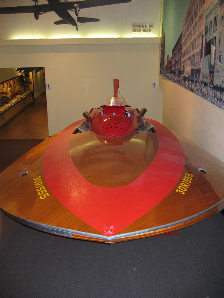
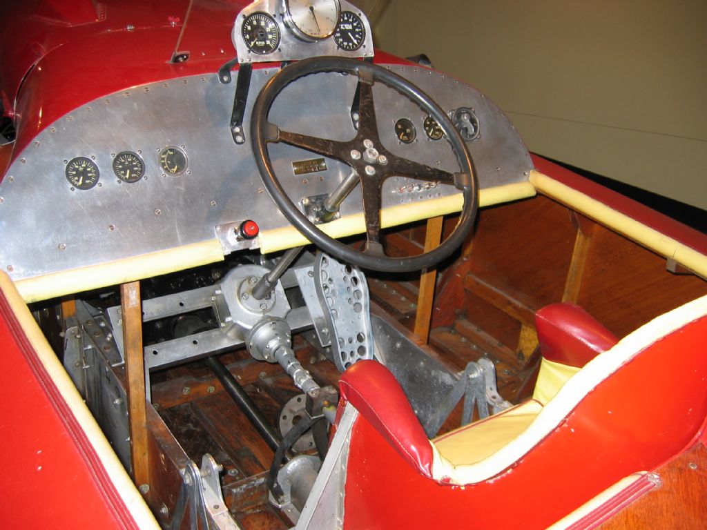
                                                      Here we go some detail of the engine cowl build. ( a mini project in its own right)
                                                       

                                                      This is the full size front view I need to replicate


                                                      The pencil lines shoe where those lumps need to be


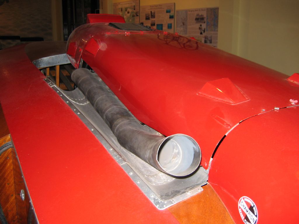
                                                      another view of the full size engine cowl not sure I’ll include that gaping hole it’s poss only open because its in a museum

                                                      thats looking close and next a view of the real dash board


                                                      shouldn’t be too hard to get this bit right apart from the gubbins in the footwell

                                                    Viewing 25 posts - 26 through 50 (of 177 total)
                                                    • Please log in to reply to this topic. Registering is free and easy using the links on the menu at the top of this page.

                                                    Code of conduct | Forum Help/FAQs

                                                    Advert

                                                    Latest Replies

                                                    Home Forums Building Kits Topics

                                                    Viewing 25 topics - 1 through 25 (of 25 total)
                                                    Viewing 25 topics - 1 through 25 (of 25 total)

                                                    View full reply list.

                                                    Advert

                                                    Newsletter Sign-up