Bryan,
Your stanchions will look better than mine!
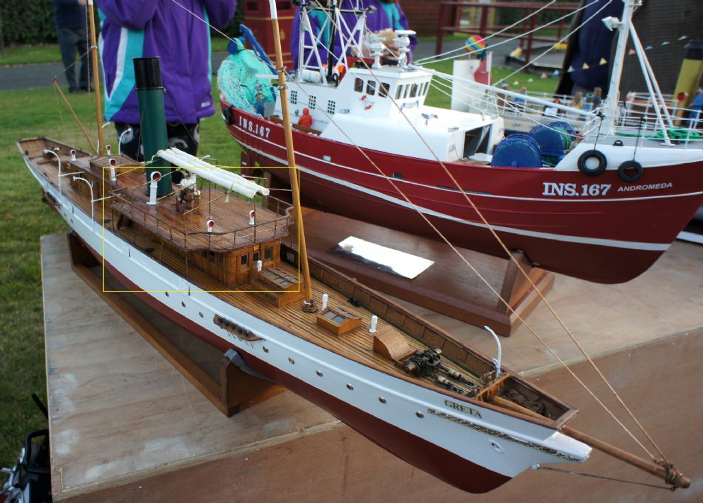
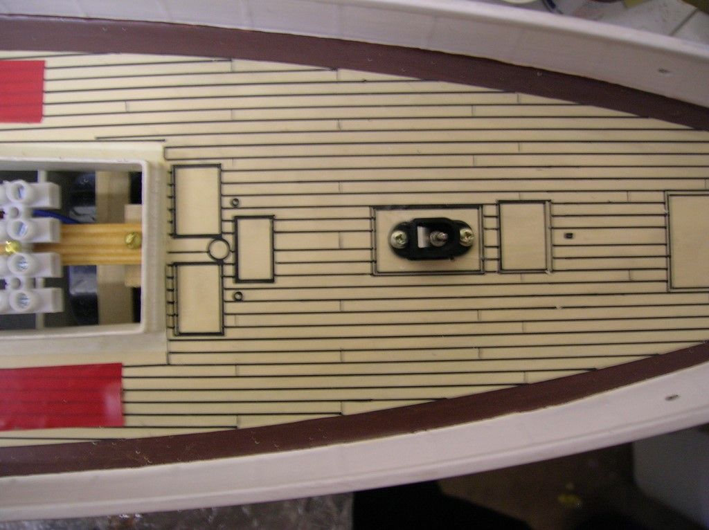
Re the charging, I should have explained in more detail. If you look at the photo at the bottom of page 71 in the Special Issue you will see two small brown boxes, one on each side of the deck just ahead of the aft skylight. These removable boxes conceal very small toggle switches one of which breaks the line from the positive main battery terminal to the ESC, the other the line from the RX positive battery terminal to the RX. These are used to energise the main and RX circuits respectively. The two charging sockets (which are identical) connect directly to the battery terminals.
So when the switches are in the off position the batteries are effectively isolated and there is no live circuit connection between the charger sockets and the ESC or RX which makes it safe to connect the chargers. The status of the main and RX circuits is confirmed by the two red LEDs mounted under the central skylight between the lifeboats which are shown in the photo at the bottom of page 72. These light up when the main and RX battery circuits are live.
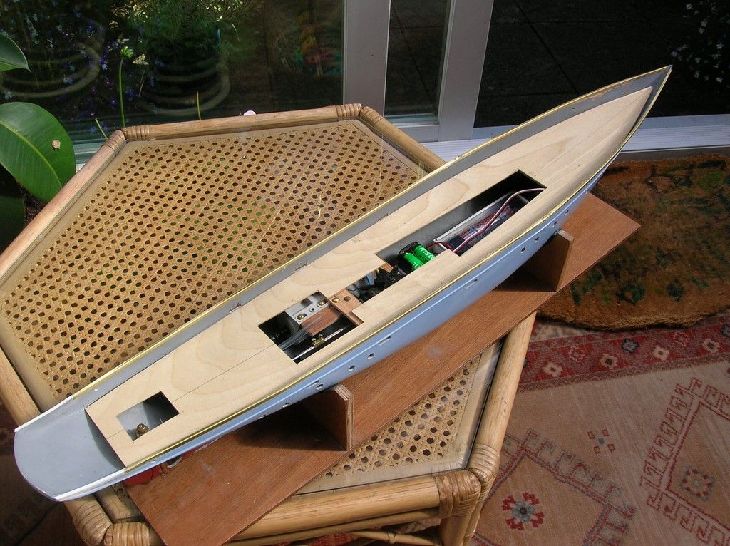
In the bottom right photo on page 70 you can see a fuse at the front of the hull opening which sits between the main battery positive terminal and the switch/ESC.
The two toggle switches are simply mounted in holes in the deck with a small coaming round them to keep water out. The plasticard boxes just fit over the top.
The location of the various bits does complicate the wiring runs but it is all logical enough and works well.
Hope this explanation helps,
Colin


