Size of a typical mast

Advert

Size of a typical mast

Home Forums Beginners Size of a typical mast

  • This topic is empty.
Viewing 15 posts - 1 through 15 (of 15 total)
  • Author
    Posts
  • #94482
    carl brotherton
    Participant
      @carlbrotherton75833

      I am building a model yacht from a plan. The plan calls for a mast and booms to be made from CF 6 mm dia rod.

      Looking at the plan, it is apparent that the mode is of very light weight construction, no doubt for those who are competent, competitive modelers. Non of which do I qualify as being.

      Is 6 mm rod the size you would expect for a club type fun model.

      The model is 650 mm long.

      Advert
      #3005
      carl brotherton
      Participant
        @carlbrotherton75833
        #94486
        Ray Wood 3
        Participant
          @raywood3

          Yes

          #94497
          Malcolm Frary
          Participant
            @malcolmfrary95515

            What Ray said.

            Just measured the mast on my Victoria, a slightly bigger yacht. 9mm diameter, aluminium tube. So 6mm carbon would sound OK. Although tube might be preferable. Competing or not, you still want the boat to behave well in a range of conditions, racing boats do this and it is a good idea to grab as many of their tricks as is feasible.

            And, when another yacht appears, a race is going on.

            #94549
            carl brotherton
            Participant
              @carlbrotherton75833

              I had thought that at 6mm that the CF would be a pultrusion type, that is the fibers being longitudinal. At present what I have found that at this size the supply I have identified is woven tube. I know that the properties of this type are pretty much unidirectional. I have large fishing road blanks of this type, which on reflection, seem to be very strong and stiff, good enough for Roach Poles and Deep sea rod types.

              Again the question is does it matter or which is the ideal type of construction?

              #94551
              ashley needham
              Participant
                @ashleyneedham69188

                Carl. Your yacht is unlikely to break a 6mm cf tube no matter what the construction of it is.

                Ashley.

                #94564
                carl brotherton
                Participant
                  @carlbrotherton75833

                  Thanks Ashley, these questions probably seem stupid. Yet if you get it wrong, some would possibly think, if you had only asked.

                  #94566
                  Malcolm Frary
                  Participant
                    @malcolmfrary95515

                    If going for carbon tube, here is a pointer from the DF65 rules –

                    G.3 Mast Construction To avoid the mast tubes splitting it is permitted, and recommended, to glue in the Mast Top Plug and glue the mast section joints. Boats supplied from 2015 onwards come with metal mast and jib boom bands to reinforce the tube ends. These rings are available as accessories and may be used on older boats.

                    Taken from –

                    https://dfracingdotworld.files.wordpress.com/2017/03/dragonforce-65-restricted-class-rules-v1-61.pdf

                    The inference is that carbon fibre tube, while incredibly strong and stiff, is inclined to split at the ends, and needs a bit of help.

                    #94946
                    Dave Cooper 6
                    Participant
                      @davecooper6

                      The experts say that CF does not suffer from 'fatigue'…

                      My belief is that all materials will fatigue given enough abuse. The CF test pieces I have are fine as long as there is no separation (anywhere) between the fibres and the resin.

                      For a solid rod – just watch for any fretting – top, bottom and sides.

                      For a tube – separation will most likely show first at the external surfaces.

                      If in doubt, I usually reinforce with Kevlar (an Aramid). I'd have thought that a 6mm o/d will be plenty strong enough. However, if you want the mast to flex – consult the others with sailing experience !

                      #94978
                      carl brotherton
                      Participant
                        @carlbrotherton75833

                        CF, as all composites are subject to fatigue/stress cracking, energy is dissipated by cracks advancing along the fibers within the material. Crack propagation being a function of cycles and stress levels.

                        All of this is well and good, which leads us to Malcolms point, that their are measures which can be taken to alleviate the situation, to reduce the stress levels, thus either reducing or eliminating the issue.

                        In some instances it is worth recognising the viable (often quoted materials properties) have limited range when compared to metallics materials. Becoming brittle at not particularly low temperatures, and in some instances entering the plastic range at temperatures we humans see as normal.

                        Finishing the discussion on polymers, they are far more restricted on loading rates than metallics quoted properties.

                        Lecture over.

                        #94982
                        Tim Rowe
                        Participant
                          @timrowe83142
                          Posted by ashley needham on 02/04/2021 12:03:27:

                          Carl. Your yacht is unlikely to break a 6mm cf tube no matter what the construction of it is.

                          Ashley.

                          Hello Carl

                          Just to remind you what Ashley said. I don't think any of us would live long enough for a model yacht mast to fail due to cycle / stress. On your boat you don't need to have a bendy mast. The rigging should keep it in column more or less.

                          A lot of what is called carbon tubs and rod is not what you might think at all. It is black but the black is in the resin and possibly carbon black used as a pigment. The fibres are glass (ie white), totally unidirectional and very closely packed to give a high glass to resin ratio. I have some tapered glider fuselages that are extremely light, a mixture of carbon and aramid and you can see the tows very easily through the clear resin. The wall thickness is a fraction of the faux carbon rods and tubes but the faux materials are fine for our purpose.
                          The most likely way of splitting the unidirectional is when attaching fittings with screws (often of the self tapping type). A pilot hole only is drilled and the screws engage with the material in its least resistant plane splitting it. That's why I I try to use adhesives only and if I can't get a large enough gluing area, insert a pin. The pin goes into a close fit hole and therefore acts like a rivet which clamps with very little expanding force.

                          You are clearly highly qualified engineer but this is probably leading you to over-think everything. Our models are usually hugely over-built with enormous margins of safety compared with what you are used to. Most model I suspect are either damaged by pets (in my case!) dropping or loading into the car.

                          I am enjoying your posts as you raise interesting questions about which most of us take for granted. Most of all you should finish your model as frankly there are no difficult technical obstacles and the satisfaction you get when it hits the water will bring you a rosy glow.

                          Tim R

                          #94983
                          carl brotherton
                          Participant
                            @carlbrotherton75833

                            Tim, you are almost certainly correct, that failure due to multiple cycles and low levels of stress are most unlikely.

                            Failure due to high stress and just a couple of acute (or single cycle) is very possible, hence the contribution by Malcolm with respect to measures to distribute stresses at points where the levels of stresses can be anticipated to be high.

                            Griffith the guy who contributed so much to fracture mechanics, from isotopic materials, 3 dimensional stress and strain, and composite materials is a fascinating read, taking metallurgy (in the 50s) in this area from a black art to a Science (Link **LINK**&nbsp and if you really want to bore yourself, as a starter then link to **LINK**. In short a outstanding British Scientist/Engineer who gets little to no recognition.

                            #94993
                            Dave Cooper 6
                            Participant
                              @davecooper6

                              Carl, unless you are planning to sail your model yacht in a hurricane, I really wouldn't worry…

                              However, if you want to re-assure yourself further, you could always use the "Buckingham Pi" theorem to relate scale speeds /bending moments etc. to full-size wind speeds.

                              Could be fun on a wet, rainy day I suppose !

                              Regards,

                              Dave

                              #95069
                              carl brotherton
                              Participant
                                @carlbrotherton75833

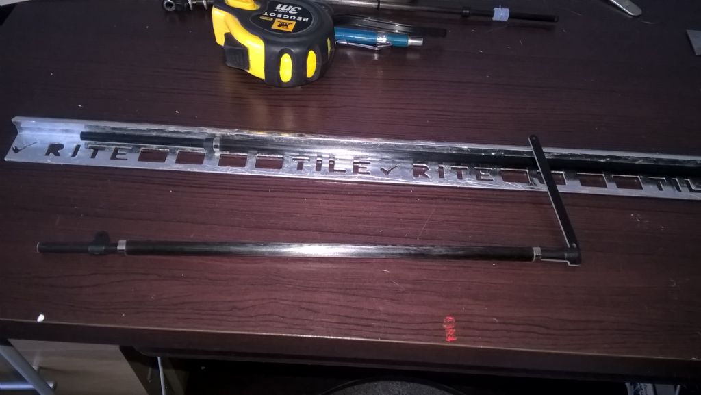
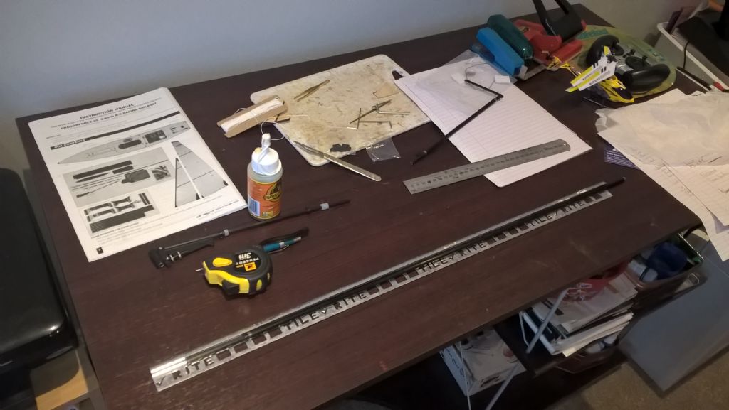
                                I now have my DF (DragonForce). As Malcolm has indicated that good practice indicates that some method of stress management at points where this can be anticipated. In the case of the DF this is in the form of metals rings.

                                wp_20210426_09_50_45_pro.jpg

                                wp_20210426_09_50_10_pro.jpg

                                On the JIF I will probably create a hybrid rigging system, using the geometry of the DF rigging and sails on the JIf. I anticipate that the mast adjustment will need to be used as the sail proportions seem to differ. The JIF being higher, presumably narrower (aspect ratio) than the DF, although the differences seem to be marginal, dependent on your view and knowledge.

                                #95080
                                Malcolm Frary
                                Participant
                                  @malcolmfrary95515

                                  There is a school f thought that reckons that higher aspect sails are more efficient, probably true for the real thing. My thought is that since model boats generally sail at the bottom of a hole in the scenery, the top bit gets moving air before the rest of the sail simply because it is less sheltered by the bank.

                                Viewing 15 posts - 1 through 15 (of 15 total)
                                • Please log in to reply to this topic. Registering is free and easy using the links on the menu at the top of this page.

                                Code of conduct | Forum Help/FAQs

                                Advert

                                Latest Replies

                                Home Forums Beginners Topics

                                Viewing 25 topics - 1 through 25 (of 25 total)
                                Viewing 25 topics - 1 through 25 (of 25 total)

                                View full reply list.

                                Advert

                                Newsletter Sign-up