The world's leading magazine for all model boating interests
Shemarah II
Shemarah II
Home › Forums › Scratch build › Shemarah II
- This topic is empty.
-
AuthorPosts
-
5 November 2011 at 13:56 #32319
Gareth Jones
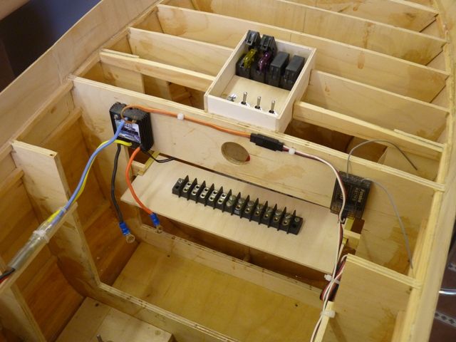
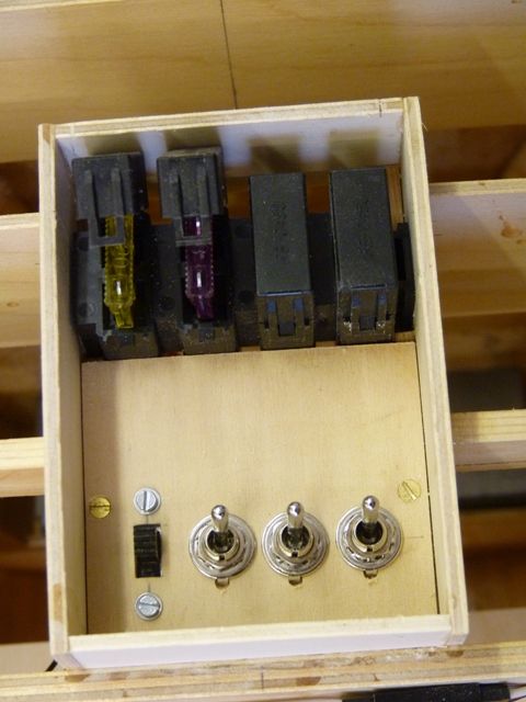
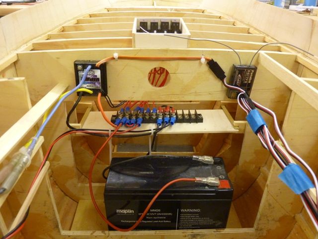
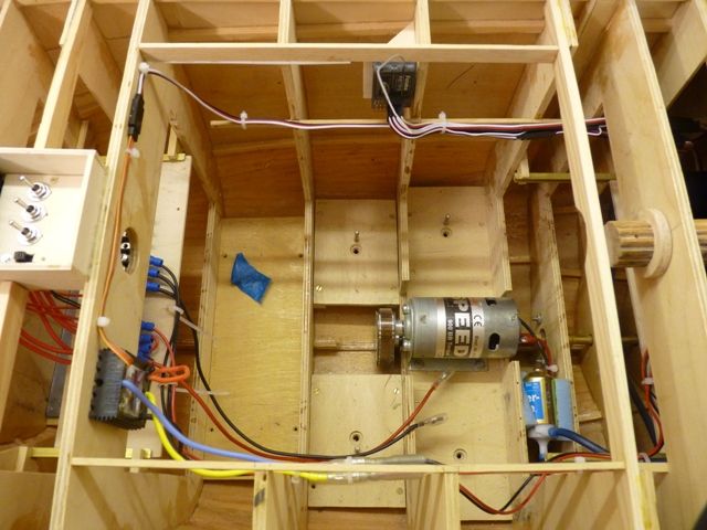
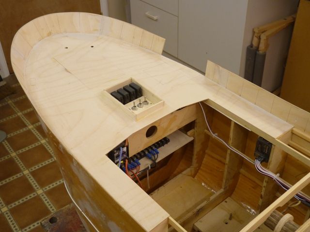
Participant@garethjones79649I have completed the shelf for the electrical installation forward of the wheelhouse, as you can see from the photo below. This shelf slides in to a pair of channel sections leaving the centre area free to access the removable ballast and battery.The receiver and speed controller are mounted high up on either side of the frame above the shelf. On the shelf is a 12 way terminal block which will act as a busbar and junction block. The battery leads will split at this block to give 4 separate circuits motor/receiver, sound system, lights/radar antenna motor and water pump. Each circuit has its own fuse and switch in a hatch just foward of the wheel house. The wiring for the lights on the mast will also go via the terminal block. On the real vessel this is a large hinged hatch where the catch is offloaded but on the model it will simply lift off in one piece for ease of access.The switches and fuses are from Maplins but the terminal block has led a very long and exciting life in its past application. It was originally part of the intrumentation system in XK527, a Buccaneer low level strike aircraft that first flew in 1961. This was a development aircraft which spent its whole life on flight trials including hot weather trials in Malta and Libya, carrier trials on Ark Royal and USS Lexington, engine development and performance tests and weapons delivery testsing. It was retired from flying in the mid 1980’s and cannibalised to build a ground rig for research and development of computer controlled fuel and hydraulic systems. I was the engineering manager of that final project and aquired lots of usefull bits when the aircraft was scrapped (all quite legitimately with authorised scrap notes.) I think I have enough terminal blocks to last the rest of my modelling life, unless I build something really huge and complicated like an aircraft carrier. However I can tell any interested viewers of Shemarah that at least one part of her went to sea for the first time about 45 years ago, has been up to 48,000 ft and has flown at 580 knots below 100 ft..Edited By Gareth Jones on 05/11/2011 13:58:34
7 November 2011 at 07:41 #32345Dave Milbourn
Participant@davemilbourn48782
I am still eagerly awaiting an answer to my question on page 6 of this thread (although I do apologise for spelling your name incorrectly.) Is there any way you can slow down a servo in only one direction, eg by using a Servomorph somehow?No. You can run a servo (or sailwinch) from one end to the other using a 2-way switched channel but a P96 in circuit will apply its settings to all servo movements, not just one way. A motor can only be run in one direction from this type of channel i.e. On or Off.There may be some mileage in fitting limit switches which stop and reverse the motor at extremes of travel, like a remote-controlled garage door mechanism, but I’m blowed if I can remember the wiring. Even then you’d have to contrive some sort of extra load or lower-voltage power supply, which would come in only in one direction.BTW I hadn’t intended to spend your money for you on an expensive pump, but you did ask the question……DM7 November 2011 at 08:41 #32348Gareth Jones
Participant@garethjones79649Thank you for that Dave, I know that a Servomorph normally controls the speed of the servo to the same value in both directions, but I just wondered if there was some clever way of making one slower than the other. No point in buying another Servomorph then.For the anchor winch I am planning to use a Hitec HS785HB sail winch servo. Its a drum type which will give me about 450 mm of travel. I will control it from the flap switch on my transmitter. That is a rotary potentiometer type and I can, to some degree at least, control the speed manually so that it drops quickly but comes up slowly. I might have to modify the drum as 450 mm of chain will take up a lot more room than 450 mm of braided cord.I have found Servomorphs quite useful for controlling the sail winches on a couple of my wife’s yachts. In that case they have not been used to control the speed but have been used to control the range of movement and end points of the sail sheets and work really well in that application. Much better than trying to limit the travel of your transmitter stick by some mechanical stop.7 November 2011 at 10:03 #32350Gareth Jones
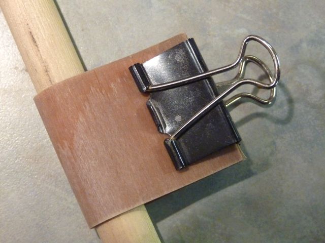
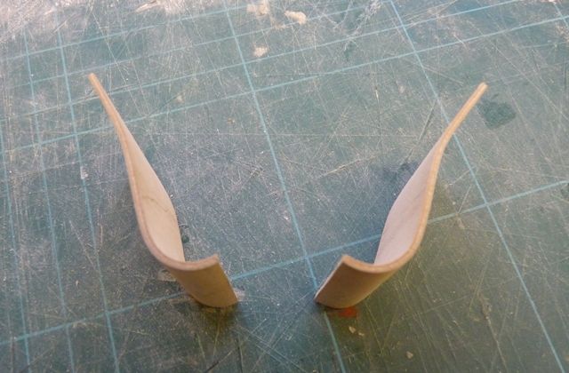
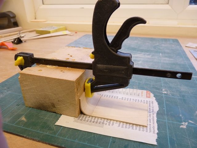
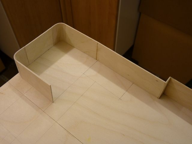
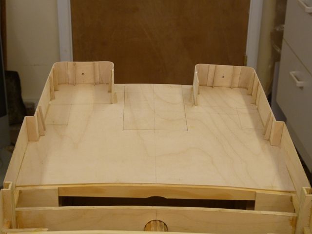
Participant@garethjones79649I have found a way to sucessfully shape the curved parts of the bulwarks in 1/16 ply and here’s the method I used. I found it was impossible to put two bends in a piece of ply and get them spaced accurately where required. Hence the only option seemed to be to make each 90 degree bend independently and glue them on to the straight sections with butt joints.The bulwarks are 38 mm high so I cut a piece of ply slightly wider, in my case 40 mm. and 100 mm long. The grain runs parallel to the short edge to make it easier to bend. I drew a line across the middle of the piece, dividing it into two sides, each 40 x 50 mm. This piece of ply was then boiled in a kettle for abut 15 minutes then pulled out with pliers and wrapped around a short length of dowel 15 mm diameter. The ends of the ply piece are matched together so that the corners meet accurately. This makes sure the bend will be true and there is no twist in the finished pieces. The ends are then clamped with a bulldog clip and the whole lot put back in the kettle for another 15 minutes.The parts were left on the radiator to dry overnight and then lightly clamped in a vice and the ply cut along the line drawn across the middle. This leaves you with two pieces, one end with a neat 90 degree bend, the other with a slightly reflex curve.If necessary put the 90 degree bend end in a vice and gently bend it so that the end face is true to the rest of the main part of the bend to be used. Then trim off the end with the reflex bend so you have a short straight section about 20 mm long on one side of the 90 degree bend. Clamp this to the side of a wooden block and glue on the next section of straight bulwark using superglue. A piece of newspaper underneath stops the whole thing sticking to your bench.You can then sand the joint smooth and if necessary apply a bit more glue or filler if you can still feel the joint. Repeat this process for the next bend and the bulwarks are built up accurately and square. Finally sand off the surplus height of the bends so that the whole length sits flat on the deck. Using the 15 mm diameter dowel I ended up with curved sections which were around 10 mm radius.This method works quite well and the superglued butt joints are quite strong. Here is the finished section on one side, still to be glued on to the hull and the vertical stiffners added. Although 1/16 ply is thicker than true scale, when the capping rail is fitted the edge will be hidden so it wont show up on the finished model.11 November 2011 at 22:55 #32410Gareth Jones
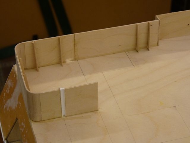
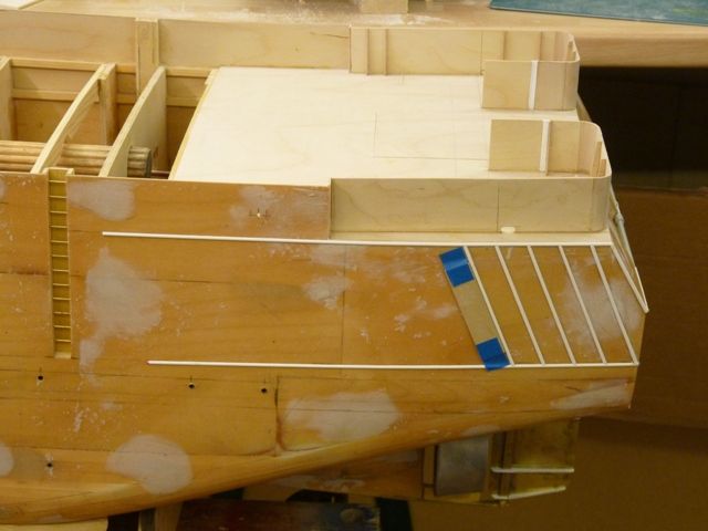
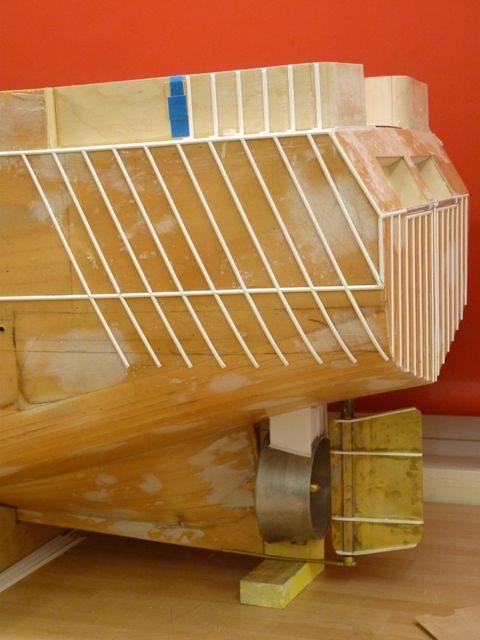
Participant@garethjones79649The stiffening flanges for the rear part of the bulwarks have now been made from 1/32 ply and glued in position. The drawing does not show any of these flanges around the stern but Jim Pottinger was kind enough to lend me the photographs he took for the original article in Model Boats magazine and these show a great deal of additional useful detail. With his permission I have copied his photos and together with pictures from the internet it is possible to clarify or correct the drawings as necessary.The vertical channel (a piece of white plastic section on the model) is used to locate a number of substantial wooden planks which close off the stern when the vessel is not deploying or recovering its fishing gear.The next job has been to continue adding the half round reinforcing bars on the rear of the hull sides. As on the transom, a short piece of ply taped in position has been used to keep the bars parallel and spaced equally apart.Again supplementary photos have been useful, as the position and number of the bars is not completely accurate on the drawings. I reckon that by the time I have finished I will have glued in place about 40 feet of 2.5 mm half round bar (bit of a conflict of units there, but you no doubt get the idea).12 November 2011 at 05:42 #32411Bob Abell 2
Participant@bobabell2Hello Gareth
You are making a super job of your model and I like the accurate positioning of the half round strips.
What are the strips for btw?
I’ve often wonderedI’m going to the Warwick Show today with the Etherow Club
Hoping to meet a few forum members?…….As I stroll around in my GE jacket, with a carrier bag of cheese butties and camera at the ready…….. for the club blogBob
24 November 2011 at 18:08 #32538Gareth Jones
Participant@garethjones79649The visit to the Warwick Show was well worth while with some interesting discussions with people on the stands, ranging from the man with what seemed like hundreds of minature models in the Spithead fleet review through Kimosubby on Thames barges to the Guild of Knot Tyers. I managed to obtain the final part of the electrical jigsaw for Shemarah in the form of an Action Electronics quadswitch. Although fencing has taken priority in the last couple of weeks I have made some progress on Shemara’s wiring.The main terminal block/busbar is well on the way to completion with all the switches and fuses connected. I have started to run the wires back to the tray in the aft end which houses the sound system and quad switch. In principle I am planning to run power wires down the LH side and servo wires down the RHS. However it has now dawned on me that while the speed controller is OK where I planned, the receiver is not in the best position and I have 4 lots of servo wires running along the RHS. I am planning to move the receiver back so that it is closer to the rear tray and the only servo wires running along the RHS will be the speed controller and, assuming I fit it, the anchor winch.When I say ‘assuming I fit the anchor winch’ its because I discovered a slight flaw in my original plan. I intended to control it using the rotary flap switch on my Futaba 6 channel transmitter. When I came to try this out a week ago I discovered my 2.4 GHz transmitter does not have a rotary flap switch, its just a two position up/down one. The transmitter with the rotary switch is a 35 MHz aircraft set that I looked at by mistake. For the time being I am going to make provision for the anchor winch servo with an access panel in the deck and get on with the rest of the model while I make up my mind what to do next.I have come up against another slight problem which some expert out there may be able to help me with. I have to put in wiring for the lights on the mast before the deck can be fitted. The mast has a single white mast head light then, working down, a pair of red lights, pair of green, pair of red and finally a pair of what I think are white lights. When trawling I assume, the green and white lights are illuminated but, the question is, do both green and both white lights illuminate or only one of each pair?7 December 2011 at 08:00 #32641Gareth Jones
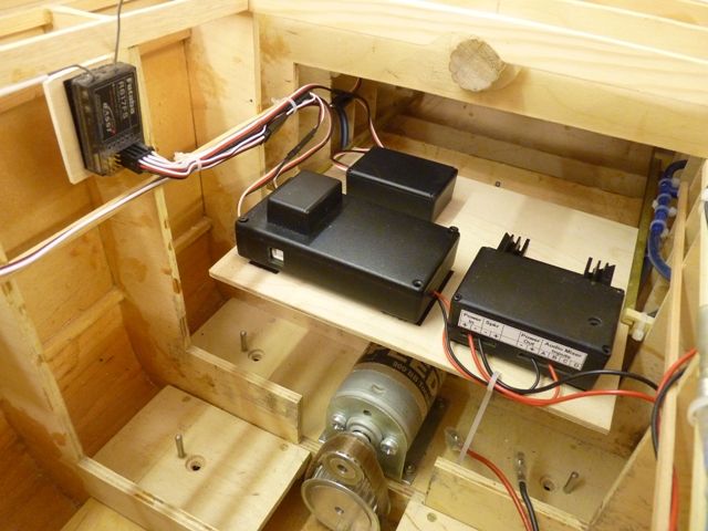
Participant@garethjones79649I was not very happy with the wiring installation, particularly all the servo wires running along the RHS of the hull. Since the vast majority of these, well 4 out of 6, start in the rear, moving the radio further back would eliminate many of the extension leads. I still wanted to put the radio receiver in a position where one of the aerials can point straight up into the superstructure so my options were limited. However I did move the receiver back and it is now mounted on the RHS as shown below.The next picture shows the rear tray pulled forward for access. I am happy now that all the power wiring can be run along the LHS of the hull so I can get on with that at a later stage. You can see one of the receiver aerials pointing upwards, the other runs forward horizontally through a short length of plastic tube just below deck level.
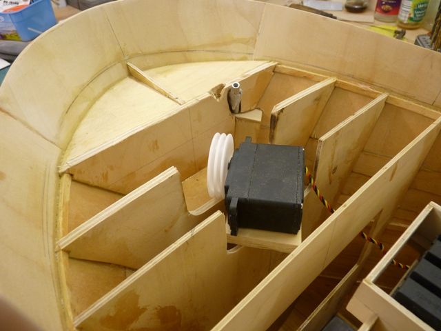
Mounted on the front row of the tray are the P100 sound unit with a P104 sound switch on top and a P101 amplifier alongside. Behind is the P62 quadswitch and still to be added are a speed controller for the water pump and a terminal block.As a diversion from electrics I have added all the half round reinforcing on the rear of the hull on the RHS.The next task was to start making provision for the anchor winch. I am not totally sure this is going to work yet but if it doesn’t I can either:-Try and make something else that does.Give in an buy a Krick anchor winch (very unlikely)Just cover over the access area and have a fixed anchorCutting through the frames in situ was a bit messy but my trusty Bosch multitool took out the biggest part. It’s a bit brutal to use on a model but very useful when you want to cut directly into the material. I finished off with a powerfile. In the background you can see where the anchor chain hawse pipe comes through and adjacent to it where my first attempt came through. The drawing is not very accurate defining this point. The chain will come up the hawse pipe, over the anchor winch gypsy
which will free wheel, and then disappear down through the deck to be
wound on the winch drum.The next task is to drill the fixing hole for the mast and then an access hole through the front bulkhead so that the wiring can be run up the mast to the lights. When that is complete the front part of the deck, which has already been cut out, can be fixed in place.7 December 2011 at 17:48 #32643RJR
Participant@rjrFascinating !! I have not long since joined the forum so am randomly picking threads to read.Having just read yours, thank you for posting so many detailed an informative build pictures and instructions.9 December 2011 at 19:30 #32656Gareth Jones
Participant@garethjones79649Thank you RJR, I am glad I am making some people happy somewhere.I had one of those shall I, shan’t I moments yesterday but finally decided to glue on the front section of deck. I am now committed to working in the dark under this area, apart from the hatch which provides access to the anchor winch servo. The deck is 1.5 mm ply and unfortunately the grain runs across the deck rather than along it but it was the only piece I had which was large enough to fit. Since the local model shops only stock ply in sheets 12 inches wide I am a bit stuck when the deck is 14 inches across. However the remaining part of the centre section can be done in two separate pieces.16 December 2011 at 08:02 #32701Gareth Jones
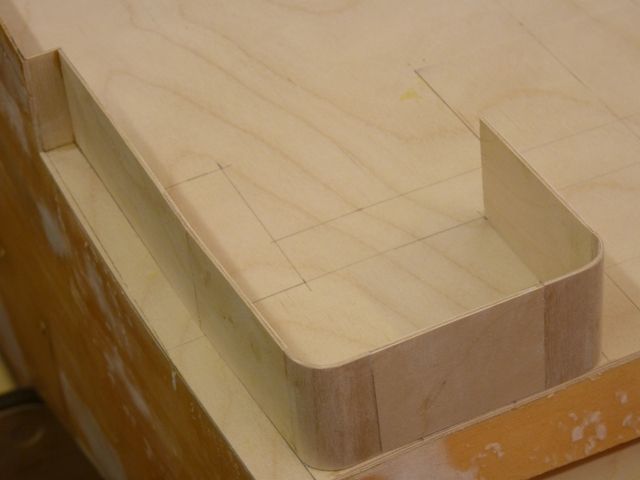
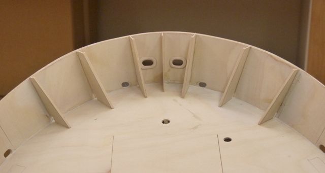
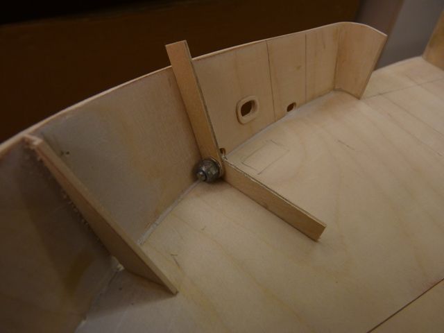
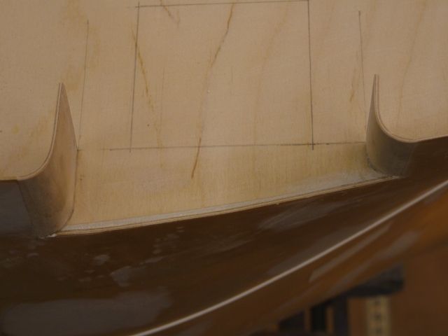
Participant@garethjones79649The first few bulwark stanchions have now been fitted at the bow. They are made from 0.75 mm thick ply with a 2.0 mm wide ply stiffening flange glued along the free edge.In order to get the angles transferred accurately when cutting them out I made a simple tool to measure the angle between the bulwark and deck. Its just a couple of pieces of ply clamped together with a small screw and stiffnut.I have also fitted the hawse plates on the inside and outside faces of the hull where the mooring hawsers will pass through the plating. These were also made from 0.75 mm ply, by cutting out rectangles 15 mm x 10 mm and drilling a 4 mm pilot hole through the middle. They were made 4 at a time for ease of manufacture. The ends were then rounded and the edges on one face chamfered. Each one was stuck on the hull using a piece of 4 mm rod to locate them on a pilot hole drilled in the hull in the appropriate place. The central hole was then opened out using a rat tailed Perma Grit file to get the correct shape. A set of small Perma Grit needle files bought several years ago has been an excellent investment. They were also used to open out the scuppers which have been cut in the appropriate places in the bow section.The bulwarks around the cod end hatch have also been finished off with a curved section, made the same way as the circular shaped bends in the stern bulwarks described earlier. However in this case the bulwarks are not at 90 degrees to the deck so the bends had to be made with a built in twist to allow for that, which was just a matter of trial and error in with a few repeated kettle boilings to get the shape right.1 January 2012 at 15:20 #32804Gareth Jones
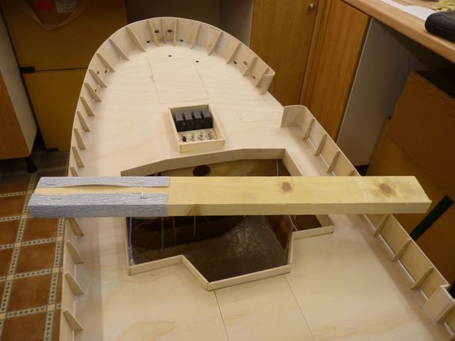
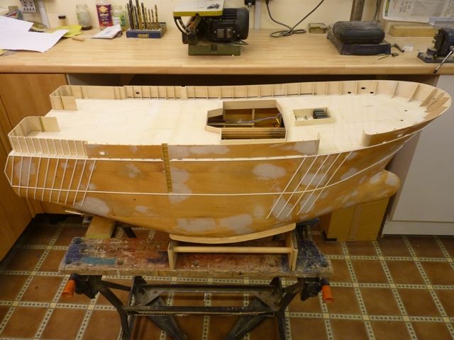
Participant@garethjones79649A year after cutting the first frame out of a 4′ x 2′ piece of ply the hull of Shemarah is now just about ready for painting. The rest of the deck has been fitted and all the bulwark stanchions are in place. The picture below shows the sanding block I used to get the tops of the stanchions level and flush with the bulwarks. It needs to be done pretty carefully as its easy to knock a stanchion loose with the sand paper. The coaming around the wheel house seat has also been fitted.All the remaining reinforcing bars have been fitted to the hull. There are a couple of small holes to cut in the hull side for a single porthole and what looks like some sort of chute in one side. There are a few small washports in each side at the level of the main deck. At the moment I think I might simulate them with a small rectangle of matt black paint rather than cut a hole and back fill it.I am not sure which bit to tackle next. I think I will give the whole hull a coat of primer as that will no doubt show up lots of areas that need filling before painting starts in earnest.I have also been giving some thoughts to the wiring, particularly for the lights. My plan is, as far as possible, to use LEDs throughout. However all the ones I have used on other boats have been very directional and not really suited for all round lights like the ones on the mast. Has anyone found any LEDs which are more suitable for such an application, i.e don’t primarily shine out of the domed end of the LED?Finally I would like to thank all those of you have shown an interest in this thread and responded to my requests for help now and then. I wish you all the best and hope you all have a good year in 2012.Gareth1 January 2012 at 18:42 #32808 John W EParticipant@johnweHi there GarethAll the best to you and yours for the New Year and I hope 2012 is a good building and sailing year for you.Your Model is looking really nice – a credit to your skills.You mention putting washports in on the side, by painting them. However, if you are anything like me – looking at this model it looks an extremely sea-worthy model – being capable of being sailed in some really bad weather. The next time its blowing a hurricane down at the lake, I bet you will be the only one sailing this model when she is finished. You will be looking for the biggest waves to take ‘green’ on the deck – as they say. Even though the hull has large deck openings to clear the water off the deck, a couple more side openings will help. So, they arent difficult to put in with a small drill and a square file – they only take minutes to do. Food for thought.KEEP ON BUILDING and I will keep me eye on this topic
 ayejohn1 January 2012 at 19:49 #32809
Gareth Jones
Participant@garethjones79649Hi John,The ‘painted’ washports I was referring to are much lower
down, They are at the level of the lower, main deck, not the top
shelter deck. If you look at the photo on the top of page 8 you can see
a couple of them just above the lower horizontal reinforcing bar. I
guess on the real ship they would be about 2-3 feet above the waterline and probably have some sort of hinged cover/non return valve on them.On
the model they would not really serve any useful purpose as most of the
inside of the hull is just one big space. If I put in real holes at
that point I would be much more likely to get water into the hull and it would be flooded to their level before any water could get out.I do agree with you that this should be a model capable of being sailed in just about any weather and I will definitely give it a go when it gets rough. Even when its calm if you give it a bit of wellie you can make the pond pretty rough for everyone else!Gareth4 January 2012 at 16:42 #32858Gareth Jones
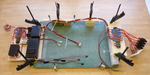
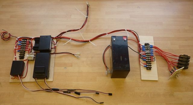
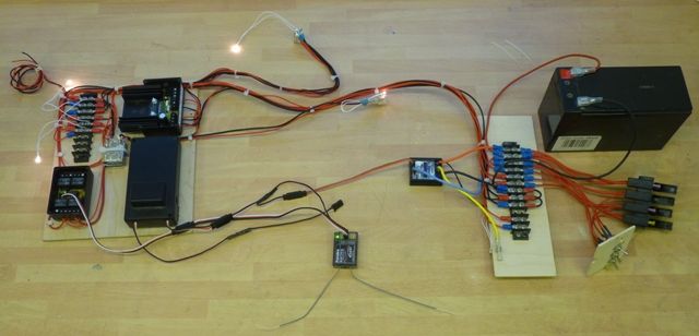
Participant@garethjones79649The last couple of days have been spent making up the wiring loom. This is the most complicated electrical system I have fitted to a model, although by some people’s standards it probably quite simple. Although there is lots of room inside Shemarah there is not a lot of access in to it. It was therefore a conscious decision to make the majority of the electrics a sub assembly built on the bench rather than inside the hull. The front and rear equipment shelves have already been described and the general run of the wiring established.Both shelves were removed from the hull and temporarily clamped to a cutting mat in their correct relative position, horizontally and vertically. The picture below shows this and although it looks a bit ad hoc and complicated, its a heck of a lot easier to run all the wires and make all the connections on the benchIn the picture the left hand end is aft, the RH end forward. All the power wires run along the LHS of the hull, all the servo wires run along the RHS. The lead running to the centre of the picture with a connector on the end is where the wheelhouse will be connected. The other pair of leads running to the middle are to the water pump and were later extended as the leads which came with the speed controller were not long enough. The coil of wire to the top left corner is the supply to the lights on the rear gantry/gallows.The picture below shows the assembly removed from the jig and laid on the bench with the battery in more or less the correct relative position.After rechecking everything was correctly connected I slaved in the receiver and speed controller and plucked up courage to connect the battery. Fortunately there were no big blue flashes or snap crackle pop noises so things were looking good. The initial test was to check the function of the Quadswitch but at first this did not seem to work. After doing a few checks with a multimeter I became completely confused as even with all the power switches off, I was till seeing about 1 volt on the input of the sound system amplifier. I spent about an hour trying to work this one out, as the standing voltage was on the amplifier’s terminals, even though it was completely disconnected from the circuit. Eventually I gave up and rang Dave Metcalfe at Action Electronics who assured me everything would be OK, it was just the residual voltage from a large capacitor in the amplifier. After this diversion I found the reason the Quadswitch system was not working was because one of my test bulbs was not connected properly – a good example of a cracked hammer I guess. Once I got the hang of timing the transmitter stick movement all four switched circuits worked fine. The picture below shows the set up with all four test bulbs lit.Tonights excitement is programming the Noisy thing sound unit prior to testing the sound system as a whole.The next major part of the vessel to be built will probably be the wheelhouse, and the drawings/plans do not really show much detail of how it is laid out inside. In some earlier correspondence I had with Shemarah’s skipper Donald Moodie he had offered to send me photographs of anything I needed. I e-mailed him on Monday evening, had a reply on Tuesday and this morning received a set of photos taken on his mobile phone showing the layout of the wheelhouse – an excellent response, extremely helpful and a good demonstration of todays communication technology. I don’t know how much detail I will be able to include but at least I can get the basic layout correct. Shemarah has not been fishing for a while but is being used in a support role to the oil industry at present – I guess its a sign of the times and a good example of how owners have to be flexible to make ships earn their keep these days. Last night she was sheltering from the storms in Scotland but this morning, just after Donald sent me the photos she was back off to sea.4 January 2012 at 17:05 #32859Dave Milbourn
Participant@davemilbourn48782GarethI know it gets confusing with Dave Marles (Prestwich Models), Dave Mainprize (Electronize), Dave Morrish (Harbor Models) and the rest, but I can assure you that Dave Metcalfe runs his own kit business (Metcalfe Mouldings) and has nowt to do with ACTion!The P100 should already be programmed with the Our Lass 11 sound set. Try it first before you connect to a PC – which will wipe the EPROM straight away.Dave Milbourn4 January 2012 at 17:25 #32860Gareth Jones
Participant@garethjones79649Davids everywhere – I do apologise for getting confused, it was definitely Mr Milbourn who gave me the advice on the amplifier. I can also confirm the advice was correct, I sat there with my multimeter connected to the amplifier and watched the standing voltage decay, ever so slowly, but decay it did.Too late on the P100 though, I had a play with it connected to my computer about a month ago, just have to start from scratch I guess.Gareth (slightly less confused)4 January 2012 at 18:06 #32861Dave Milbourn
Participant@davemilbourn48782I know – common as muck, aren’t we?Anyroad up, m’duck (he said, slipping comfortably into the vernacular….) you can use the software’s Quick Setup Screen to load the ‘Our Lass II’ sound set via a USB connection. It should take about two minutes, most of which time is spent waiting for the little green caterpillar to crawl across its box. Once the screen says Download Successful you should click OK and exit the program. Unless you wish to change the sounds there is no need to venture past this screen.DM4 January 2012 at 19:46 #32865Gareth Jones
Participant@garethjones79649Dave,I have just done the green caterpillar thing and I am now about to retire to the shed and try it out.Gareth4 January 2012 at 20:15 #32866Gareth Jones
Participant@garethjones79649It works !A bit of fine tuning required though, firstly to remove the supplementary sound from position 1 so I dont get the blast of a horn every time I try and switch off the seagulls etc.Secondly the supplementary sounds seem proportionally louder than the engine. I will have to read the instructions and play around with the system when I have decided on the supplementary sounds to use and see if this is still the case or can be changed.Before trying the unit I set the volume potentiometer fully anti-clockwise thinking it would be the quietest setting. Unfortunately it was the loudest and the first blast on the horn gave our trainee hearing dog (and me and my wife) a heck of a fright.GarethEdited By Gareth Jones on 04/01/2012 20:17:05
5 January 2012 at 08:59 #32869Dave Milbourn
Participant@davemilbourn48782Don’t forget that deeper sounds travel further and louder than higher frequencies, so if you muck around with the levels of the other sounds then they may be too quiet once the model is on the water. The only way to change the volume of each sound is to run the relevant WAV file through Audacity and lower the amplitude, then save and convert the file as a new sound for loading onto P100.
5 January 2012 at 12:41 #32870Gareth Jones
Participant@garethjones79649Dave,I am happy that everything works as it should so I plan to wait until I have the speaker fitted in the wheel house floor and I know what the finished sound is like before I start tinkering with the system again.Gareth6 January 2012 at 04:51 #32876Bob Abell 2
Participant@bobabell2Hello Gareth
An excellent quality build model!
Access to the motor drive etc looks very restrictive?
Bob
6 January 2012 at 16:29 #32882Gareth Jones
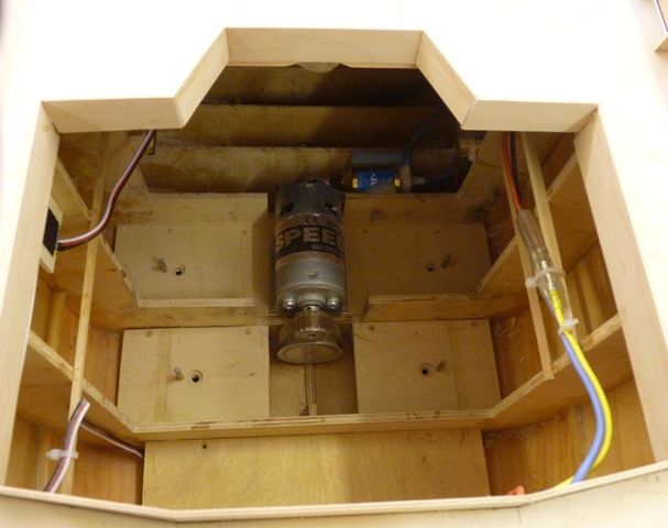
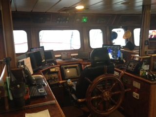
Participant@garethjones79649Hi Bob,Access to the motor is fine, its just held with 4 nuts onto studs set in the floor. A short socket driver is all you need to undo the nuts then snip the tyrap holding the wires to the side, disconnect the connector on the right of the picture, pull the motor forward so the flexible coupling slides off the splines and Bob’s your uncle, its out in less than 2 minutes, Its just as easy to refit, maybe it takes 5 minutes as starting the nuts on the threads is a bit fiddly to do by feel. The prop shaft is sealed with self lubricating bearings so there’s no need for access to that.Here’s an interesting fact about the real Shemarah. I was intrigued by the picture below, sent to me by the skipper Donald Moodie. The ship’s wheel is mounted behind the seat which looks a bit odd. I assumed, correctly as it turned out, that the wheel is just a back up, the ship is normally steered using an autopilot. However Donald told me the wheel has only been used in anger once in the 15 years or so that the vessel has been in service.Edited By Gareth Jones on 06/01/2012 16:29:29
8 January 2012 at 19:20 #32905Gareth Jones
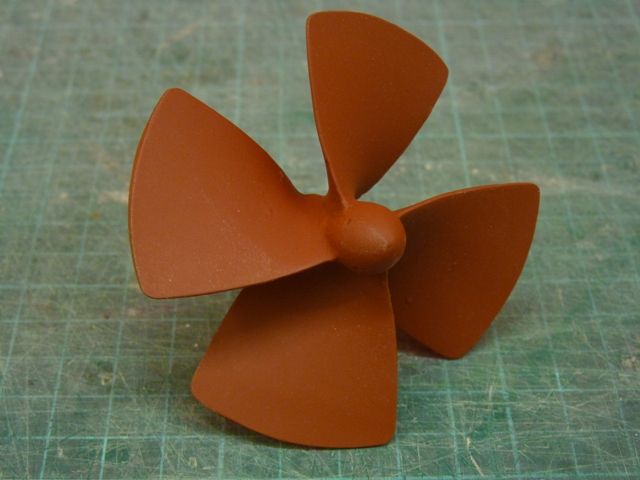
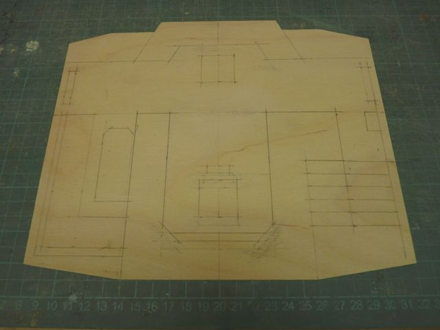
Participant@garethjones79649The first bit of painting has now been done, but its only one small piece, the propeller, which has been finished in Halfords red primer, just to see what it looks like. In the past I have generally used Humbrol spray paints but Shemarah is so big I thought they would work out a bit expensive. The next steps are to paint the deck and prime the inside of the bulwarks in Halfords grey primer, then what will probably be a fairly protracted masking session before spraying the inside of the bulwarks white. I then plan to add the bulwark capping strip before spraying the whole of the hull in red primer.I have also cut out and begun marking out the wheel house floor. The layout is based on the plan but modified to match the photographs taken inside the real thing. It is not 100% accurate but its much closer than the original plan. Essentially I used the window positions in the photos as reference points and adjusted everything around them. The bottom of the picture is forward on the model -
AuthorPosts
- Please log in to reply to this topic. Registering is free and easy using the links on the menu at the top of this page.
Code of conduct | Forum Help/FAQs
Latest Replies
Home › Forums › Scratch build › Topics
-
- Topic
- Voices
- Posts
- Last Post
-
-
Fairey Huntsman 28
1
2
…
7
8
Started by:
 Chris Fellows
in: Build Blogs
- 2
- 197
-
15 hours, 8 minutes ago
 Colin Bishop
-
Vic Smeed’s Silver Mist
1
2
…
33
34
Started by:
Bob Abell 2 in: Scratch build
- 5
- 828
-
18 hours, 28 minutes ago
Tim Cooper
-
Building a hull.
Started by:
 mick east
in: Scratch build
- 7
- 16
-
1 day, 23 hours ago
 mick east
-
Fairey Faun
1
2
3
Started by:
 Chris Fellows
in: Build Blogs
- 7
- 60
-
2 days, 16 hours ago
 Ray Wood 3
-
superglue allergy
Started by:
 Alasdair Allan
in: All things floating
- 5
- 12
-
3 days, 16 hours ago
Tim Cooper
-
Model Yacht Racing – The future ??
Started by:
 Ray Wood 3
in: Sailing Models
- 4
- 4
-
4 days, 10 hours ago
 Richard Simpson
-
Vic Smeed’s Legacy
Started by:
 Colin Bishop
in: All things floating
- 6
- 15
-
4 days, 14 hours ago
 Colin Bishop
-
Eezebilt RAF Fire Boat
Started by:
Tim Cooper in: Build Blogs
- 4
- 9
-
4 days, 14 hours ago
 Colin Bishop
-
Feathered Friends
Started by:
 Chris Fellows
in: Soapbox
- 3
- 9
-
5 days, 10 hours ago
 Richard Simpson
-
4D Modelshop
Started by:
Keith Long in: Scratch build
- 6
- 9
-
6 days, 17 hours ago
 Colin Bishop
-
Fairey Huntsman 31
1
2
…
5
6
Started by:
 Chris Fellows
in: Build Blogs
- 14
- 139
-
1 week ago
 Chris Fellows
-
John Cobb’s Crusader
1
2
…
7
8
Started by:
 Paul T
in: Scratch build
- 1
- 192
-
1 week, 1 day ago
 John W E
-
Complex Automata
Started by:
 Colin Bishop
in: Soapbox
- 1
- 1
-
1 week, 2 days ago
 Colin Bishop
-
RAF Fireboat ID
Started by:
 Dave Reed
in: Collectors’ corner
- 8
- 24
-
1 week, 3 days ago
Tim Cooper
-
TID steam tug 42″ – PN Thomas drawing enlarged
1
2
Started by:
 Ray Wood 3
in: Scratch build
- 8
- 33
-
1 week, 4 days ago
 Richard Simpson
-
Lady of Skye (puffer)
1
2
Started by:
 mick east
in: Build Blogs
- 9
- 43
-
1 week, 5 days ago
 Richard Simpson
-
Todays Boating
1
2
…
210
211
Started by:
 ashley needham
in: All things floating
- 84
- 5,252
-
2 weeks ago
 Colin Bishop
-
Sea Rover Restoration
Started by:
harry smith 1 in: Collectors’ corner
- 4
- 10
-
2 weeks ago
 Richard Simpson
-
WORKSHOP LIGHTING
Started by:
 John W E
in: All things floating
- 9
- 18
-
2 weeks, 1 day ago
 Colin Bishop
-
Mayhem Website Down
Started by:
 Colin Bishop
in: All things floating
- 4
- 10
-
2 weeks, 4 days ago
 Colin Bishop
-
MAGGIE M trawler
Started by:
 sammyk
in: Buy/Sell or Trade
- 2
- 3
-
2 weeks, 4 days ago
 sammyk
-
meter
Started by:
 Alasdair Allan
in: All things floating
- 5
- 16
-
2 weeks, 6 days ago
 Chris Fellows
-
River Queen 2”- 1’.
Started by:
Richard B in: Steam powered models
- 5
- 7
-
3 weeks ago
Richard B
-
Deluxe Superphatic Glue.
Started by:
 Colin Bishop
in: All things floating
- 4
- 12
-
3 weeks ago
 Chris Fellows
-
How to add photos to your posts
Started by:
 Colin Bishop
in: Adding Images to Forum Posts
- 3
- 16
-
3 weeks, 1 day ago
Len Morris 2
-
Fairey Huntsman 28
1
2
…
7
8
-


