Shemarah II

Advert

Shemarah II

Home Forums Scratch build Shemarah II

  • This topic is empty.
Viewing 25 posts - 51 through 75 (of 371 total)
  • Author
    Posts
  • #31806
    Gareth Jones
    Participant
      @garethjones79649
      Well, as the saying goes, ‘There is some good news and some bad news’
       
      The good news is Shemarah fitted in the bath and has been ballasted down to within a few mm of the correct waterline, near enough for now anyway. I tested the motor and although its a bit noisier than I would have liked, it seems to provide plenty of thrust. The motor is a Graupner 900 BB Torque driving a 75 mm prop in a Kort nozzle with a belt drive speed reduction of about 2:1. At full throttle the wattmeter indicated that the motor drew 6.4 amps at 11.25 volts with an input power of 75 watts. I will do a more precise set of measurements, including the static thrust, in the pond, where its a bit easier to tether the boat.
       
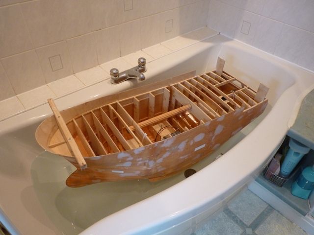
      However the bad news was that I needed much more ballast than I expected. Heres a picture of the unballasted model.
       
       
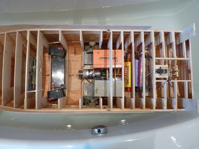
      Here is a picture of the fully ballasted model with all my available lead, 4 additional lead acid batteries, 5 NiCads and an assortment of scrap bits of lead from under my workbench.


      When I came to lift the full ballasted model out of the bath to put it on the bathroom scales I thought flipping heck, this feels much heavier than when I tried 7 house bricks and it weighed 45 lb. The scales proved the point as the model weighed near enough 60 lb. At the moment I don’t understand the reason for this, maybe Dave Metcalf’s figure of 70 lb on the drawing is going to turn out more accurate than Paul Freshney’s 43 lb in the magazine article. It looks like some of the ballast will have to be removable and fitted when the boat is in the water. Still it’s a bit more progress and weather permitting it will be off to the pond in Goole tomorrow to try out the complete system.

      Advert
      #31807
      Gareth Jones
      Participant
        @garethjones79649

        PS, the other good news is that there did not seem to be any water leaks.

        #31841
        Gareth Jones
        Participant
          @garethjones79649
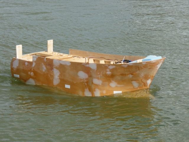
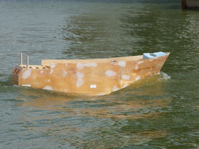
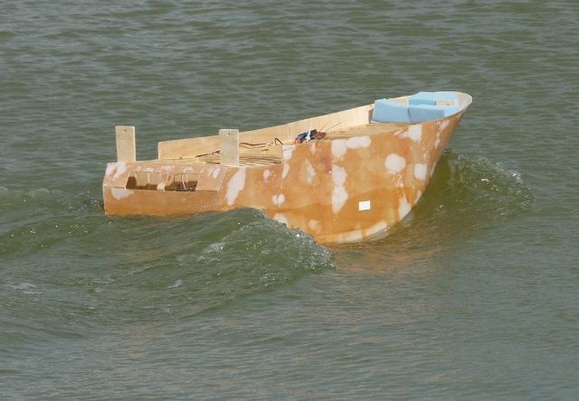
          Shemarah had her first taste of pond water at the weekend as I carried out some preliminary performance tests. I think I have a good motor and propeller match in the model but I have been slightly apprehensive as its looks so small inside the cavernous hull. The model is a snug fit in the boot of my Jazz but its quite a compact shape and the built in handle makes shifting it reasonably easy.
           
           
          The model was ballasted to around the expected fully completed weight and the sailing weight on Saturday was 25 Kg or around 56 lb. The short rectangular strips of white tape mark where the design waterline should be (along the bottom edge of the strips).
           
          On the water performance was excellent with plenty of power in reserve.
           

          Manoeuverabilty was very good and the model will turn within about twice its own length at quite low power. I made the rudder about 20% longer chord than scale size as I have found in the past this improves steering ability without detracting from the scale appearance of the model, (and you can always shorten it afterwards if you wish)
          There is also adequate thrust in reverse, and the models tracks reasonably straight but there is no significant steering capability from the rudder in reverse.
           
          The motor is a Graupner 900BB torque driving a 75 mm kort prop and nozzle via a 2.1:1 reduction belt drive.
           
          The measured motor input power was 10.85 Volts, 6,5 amps and 71 watts and the prop speed was 2080 rpm which is about 67% of the motor free running speed so its a good balanced and efficient combination.
           
          It was a very encouraging first trial with no need for any propulsion changes. The next step is to make provision for the final, removable lead ballast installation. I added the temporary ballast while the boat was in the water to get the balance correct but I did lift the fully ballasted model out of the pond using its built in handle. However I think making a proportion of the ballast accessible and removable is the way to go.
           
          #31842
          Tony Burton
          Participant
            @tonyburton83970
            Hi Gareth
            The boats starting to look real good on the pond. She makes a good hole after the bow wave.
            I spoke to one of your members at Balne Moor last sunday and he invited me to come and have a look at your pond. I tried to get on the web site but its down at the moment.Do you still sail on saturdays. If you do i will probably call in this coming weekend
            Tony
            #31843
            Gareth Jones
            Participant
              @garethjones79649
              Hi Tony,
               
              Glad you like the pictures of Shemarah. Goole MBC do still sail on Saturday afternoons from around 1:00 pm onwards and quite a few people go on Wednesday afternoon as well.
               
              Gareth
              #31845
              Gareth Jones
              Participant
                @garethjones79649
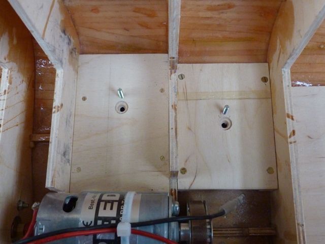
                Today I have modified the ballast arrangements and Shemarah has been back in the bath to test the balance. I have added an additional pair of ballast weight platforms just forward of the centre of the hull.
                 

                The photo above shows the left hand pair, each with a screw/stud to locate in a hole in the bottom of the ballast weight and a recess to accommodate the screw which holds the lead sheets together in each pack.
                 

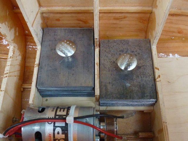
                Each pack is held together by a screw which passes through all the sheets and engages a rather elegant stainless steel knob to allow the whole pack to be easily removed. I will probably replace the threaded locating studs with plain brass rods with a slight taper in due course as the threads tend to create slivers of lead each time the ballast weight is replaced. The front pair of ballast weights weigh 2.35 kg each and the rear pair weigh 3.35 kg each. Assuming the total all up weight of the model ends up around 25 kg (60 lb), I will have 11.4 kg (approx 25 lb) of easily removable ballast, leaving the hull weighing around 13.6 kg (35 lb) when it is lifted in and out of the water.
                 
                I have also moved the ballast weight at the back of the hull forward by two frames to allow it to be fitted lower down. Tests on the pond and in the bath suggest the model will not be particularly lively in pitch so moving the ballast forwards will not adversely affect the overall stability. Each individual ballast weight can be adjusted by adding or removing sheets to get the final required weight. Its close enough now to allow the model to be sailed for test purposes, or just for fun.
                 
                The next step is to begin marking the hull ready for the fitting of all the half round bars on the rear sides, transom and adjacent to the cod end hatch. I also plan to start trimming the bulwarks, marking out the scuppers and anchor recess and removing the blanks fitted over the steps in the sides of the hull prior to fibreglassing. I also need to fit the plates that support the Kort nozzle and there is also the odd bit of filling and rubbing down to do here and there before the hull can be primed. Should keep me from getting bored for a while, much more interesting than rubbing down fibreglass resin.
                 
                I am pondering the possibility of making the anchor and cod end hatch operate as the real thing but have not yet worked out the best way of doing this.
                #31895
                Gareth Jones
                Participant
                  @garethjones79649
                  Shemarah had a couple more outings to the Goole and York ponds at
                  the weekend and the removable ballast principle was proved to work OK so
                  it looks like a go-er.
                   
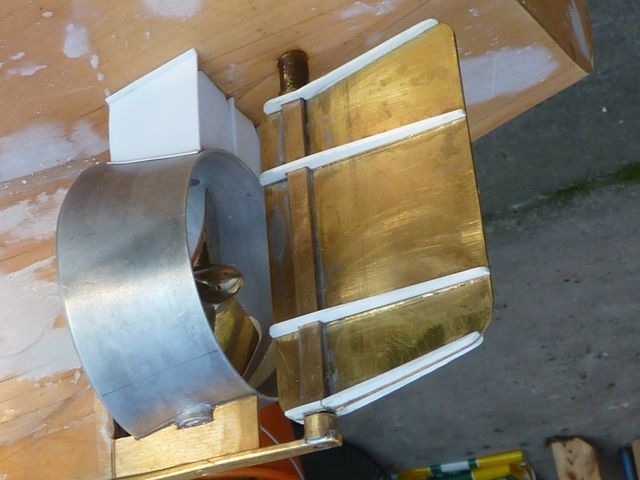
                  The last couple of days have been spent making the
                  supporting structure for the Kort nozzle. This is not shown on the
                  plans but can be seen on photos of the ship out of the water. The
                  actual design does not look very elegant, and would seem to me to be a
                  bit draggy but then I know nothing about hydrodynamics. The upper
                  supporting structure was made from 1.0 mm plastic sheet. It was really
                  awkward to make as it is all different angles and curves and it is
                  almost impossible to take proper measurements on the model. It was all
                  built by trial and error and I have thrown away two or three examples of
                  each part before I got them all to fit. The lower supporting ‘fill in’
                  piece was easier and was just made by cutting and shaping a piece of 6
                  mm ply.
                   
                  Having assembled all this I found the rudder was no longer
                  aligned and was stiff to rotate as the stiffness of the complete nozzle
                  mount had removed any compliance. The rudder bearing tube was removed
                  by inserting a soldering iron into the bottom end and allowing the whole
                  thing to warm up and soften the araldite. The tube was removed and the
                  tube and hole were then cleaned up and reglued while the whole assembly
                  of nozzle and rudder were held in alignment. Its now fine and the
                  rudder is free to move. I always use araldite in this sort of situation
                  as heating the metal part with a soldering iron or small blowtorch will
                  soften ithe glue. It works well if you need to remove a propshaft tube
                  for example, although it might be risky in a plastic hull.
                   
                  The next job, while I am waiting for my half round reinforcing strips to arrive, is to fit a small water pump to
                  eject water from three holes in the port side of the hull. I guess one
                  of these is a cooling water flow, one may be a bilge pump but what the
                  other one is I have no idea. However they are quite prominent on
                  photos of the real ship so I have decided to include them as a working
                  feature.
                   
                  #31944
                  Gareth Jones
                  Participant
                    @garethjones79649
                    The water pump idea has been put on standby over the last few days and I have been fixing the steps in the hull and installing the anchor recess. I originally built the steps in at an early stage of the hull construction as I was reluctant to have to cut a slot in the side of the hull at a later date. They were covered with a temporary ply plate when the hull was fibreglassed. However due to an error reading the drawing (it is confusing) I thought the scuppers intersected and cut through the steps on each side. Therefore I cut the top section off, not very neatly, because I assumed I would have a 3 mm slot to tidy the gap up. Unfortunately I later realised, after looking at some photos, that the step structure is continuous and it is the scuppers that are interrupted. Rather than try and reattach the bits I cut off I decided to bite the bullet, cut out the existing steps and make a new set. The picture below shows on of the completed assemblies.
                     

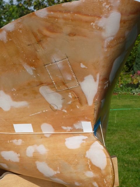
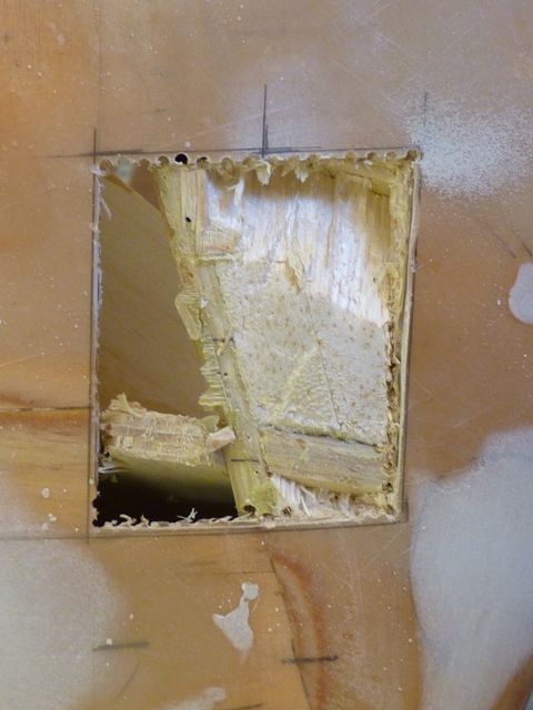
                    The next step was to cut the recess where the anchor fits. This was a bit tricky to size and locate as the view on the drawing shows the recess at an angle. However reference to my collection of photos helped and I marked and chain drilled the hull in what I think is the right spot. The piece of string marks the waterline which was one of my main references.
                     
                    There is some supporting structure behind the cut out which had to be cut away but helps support the sides of the recess.
                     
                     
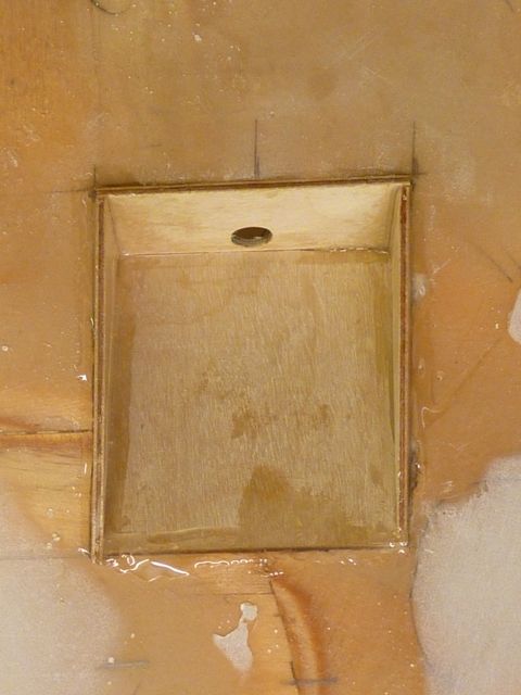
                    Lining up the hawse pipe that the anchor chain will run down was rather confusing. The drawing plan view does not line up with where the anchor sits. It does not seem logical that the connecting hawse pipe is curved or kinked so it was back to the photos again for help. These solved the problem as they showed the location of the winch on the deck plan is not quite correct, it is angled differently from the real position. The back, top and sides of the recess have been glued in position and will be ready for sanding flush with the hull skin tomorrow.
                     

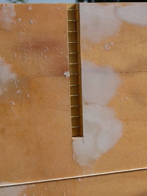
                    My half round reinforcing has arrived and I will be practising fitting the first few short pieces around the sides and top edges of the recess. I am planning to have a working anchor but at the moment I am not sure how I will do this. I have looked at the Krick working winches but they are expensive and I am not convinced the anchor will fall under its own weight because of the friction of the drums, winch gypsy and the hawse pipe. They also need to be operated from a proportional channel of the radio system which would be a nuisance. At the moment my thoughts are to uses a drum type sailwinch to raise and lower the anchor. It may not fall quite as fast and freely as real life, and it may be lifted up a bit too quickly. However on cost and simplicity of engineering it looks a promising option. I think I could operate it from the gear up/down switch on my transmitter which would be a neat solution if it works. ( Mr Milburn – Can you slow a servo down in only one direction using a Servomorph?)
                     
                    While cutting the hole for the hawse pipe it dawned on me that I have another problem to overcome in the same area. There are a number of lights on the mast and the wiring needs to run down the inside – easy enough I think. However the mast sits close to the bow on a compartment that is now completely enclosed. In order to get wiring to it I will have to cut a hole into that compartment and through several other frames. I guess I will put in a piece of tubing as a conduit to run the wiring through. While it will be a bit tricky now, it would have been a nightmare job if I had not realised till after the deck was fitted.

                    #31973
                    Gareth Jones
                    Participant
                      @garethjones79649
                      Today has been spent fitting the half round rod on the anchor recess which is now complete apart from the tube up to the deck which will have to wait until the deck is marked out and fitted.
                       
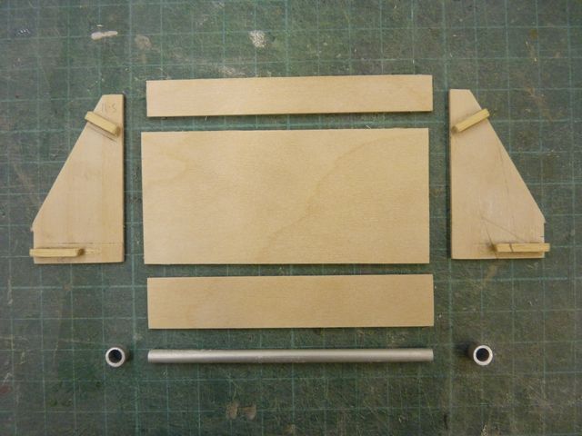
                      This afternoon I have made and fitted the two transom doors and rollers. Here are the individual parts of one side.
                       
                       
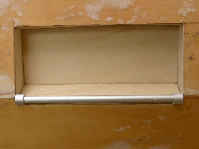
                      Here is one door fitted and the roller just temporarily laid in position. I will give the door and recess a coat of primer before fixing the roller.
                       
                       
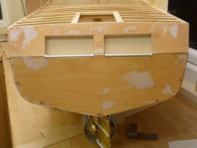
                      Heres a view on the transom with both doors fitted.
                       
                       
                      The next step is to fit the half round reinforcing bars on the transom but thats tomorrows job.

                      #31979
                      Tony Burton
                      Participant
                        @tonyburton83970
                        Hi Gareth.
                        I thinks she is looking good……I wish I could build to the same quality as you do .
                        I have been to Goole twice now and joined the club but dont seem to have been there at the same time as you.
                        Last Saturday I used my mini cam on the front of my boat at Goole and have just posted the disc to Bob
                        Cheers tony
                        #31980
                        Bob Abell 2
                        Participant
                          @bobabell2
                          Hello Gareth
                           
                          Looking good and you seem to be enjoying the build!
                          Keep up the good work
                           
                          Bob
                          #31985
                          Gareth Jones
                          Participant
                            @garethjones79649
                             
                            Tony,
                            I dont think my build quality is that exceptional, lots of people have much better practical skills than I do. I like to think that I pay attention to detail and I am quite thorough in all my control, wiring and propulsion systems installations, but then that was my job for 40 years.
                            Unfortunately we are not often able to visit the pond at Goole for the main sailing session on Saturday sfternoon. We live about half an hours drive away but on Saturday our daughter works at a riding stables half an hour away in the opposite direction and since we have to pick her up mid afternoon its a bit awkward.
                            Bob,
                             
                            Yes I am enjoying the build, its just taking longer than I expected. I seemed to able to find more time for boat building when I was at work. Now that I have retired there seem to be so many other things to do and I dont appear to be able to get up at 5:00 am for a couple of hours in the shed any more.
                             
                            Gareth
                             
                            #32005
                            Gareth Jones
                            Participant
                              @garethjones79649

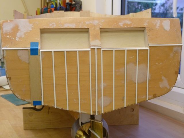
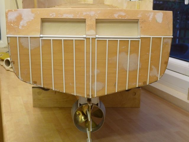
                              The reinforcing bars have now been added on to the transom. Following Bluebird’s advice I used a strip of 1/32 ply to act as a template and get the strips evenly spaced across the area.

                               
                              The strips are 2.5 mm Raboesch styrene attached with thick superglue, which gives just enough time to slide them to the right position and fills the gap around the edge of the strip pretty well. Heres the final result.
                               
                               
                              Before I can do the strips on the side I need to build up the bulwarks on the aft end where they are stepped inwards to provide a stowage area for the trawl doors. Before I can do that I need to fit the deck. However before I commit myself to removing access to a large area of the ‘innards’ I am going to fit a sliding tray on which some of the electronics will be mounted (Noisy thing sound system, sound switching unit, amplifier and a switching unit for the lights and anything else I decide to control from the radio system. The main power distribution, fuses and switches will be on a similar sliding board in the front end with working access through the main hatch forward of the wheelhouse. All will come clear in the next set of photos I hope. (no smoke and mirrors here)

                              #32040
                              Gareth Jones
                              Participant
                                @garethjones79649
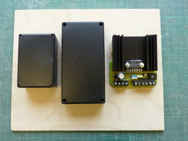
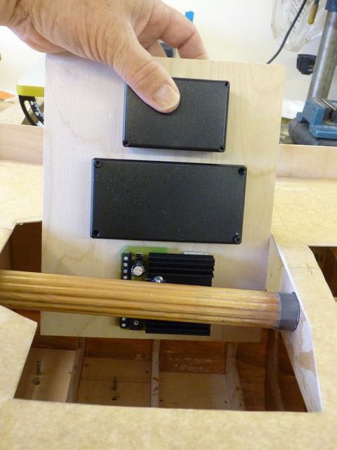
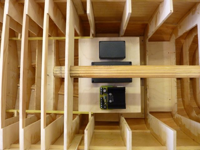
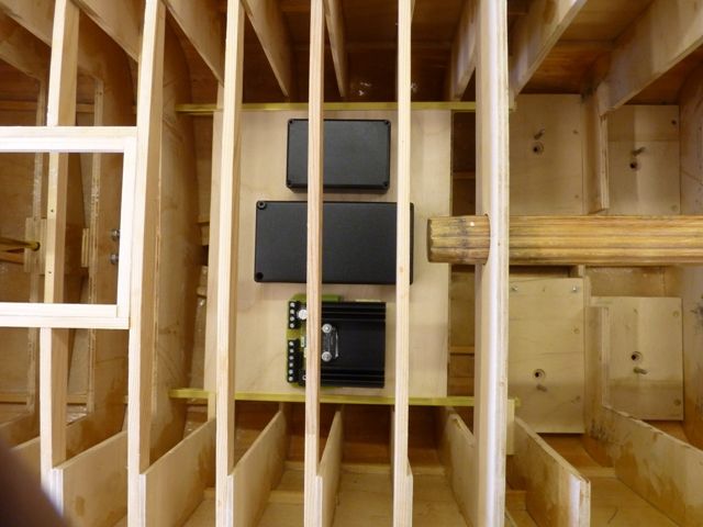
                                In principle there will be two ‘trays’ of electronics in Shemarah. The forward one will hold the power supply fuses and the main switches which will be accessible through the hatch forward of the wheelhouse. The aft tray is shown below and will hold the P100 noisy thing, amplifier a radio controlled switch unit and any other odds and sods that turn out to be required. The tray itself is just a piece of 3 mm ply with the boxes temporarily stuck on with double sided tape below.
                                 

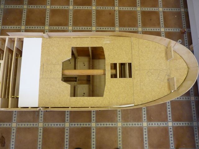
                                I have made a card deck template with the main access holes cut out as shown below.
                                Heres the aft electronics tray being inserted through the access hole where the main superstructure will fit.
                                 

                                And heres the tray with the end inserted into the start of the two pieces of 6 x 6 mm brass channel which act as rails to allow it to be slid in to the rear of the hull.
                                 

                                The rails are supported on short pieces of strip timber glued to the flanges of the hull frames. The picture below shows the tray slid into position at the back of the hull centre section.
                                 

                                The idea is to have a single loom running along one side of the hull to connect the two trays together. The receiver will be mounted high up on the side of the hull well away from all the power wiring. The speed controller will be on the other side. A flying lead with a multi pin socket will run from the aft tray to a point at the rear of the superstructure access hole. A mating plug with a flying lead will be fitted on the superstructure to connect up the lights, audio speaker and radar antenna drive. Pretty well all the wiring can be made up and tested on the bench before fitting the two trays into the hull. This should result in a reliable neat installation with the minimum of scarred knuckles through trying to work through a little access hole with minimal visibility of what’s going on. The whole lot can be removed for trouble shooting or modification without tearing half the boat apart. 
                                 
                                Well that’s the plan anyway.  Every model boat I have made so far has ended up with a major modification at a late stage in build when its really awkward to do. Hopefully this time will be different.
                                 
                                 
                                .

                                Edited By Gareth Jones on 09/10/2011 16:15:11

                                #32086
                                Gareth Jones
                                Participant
                                  @garethjones79649
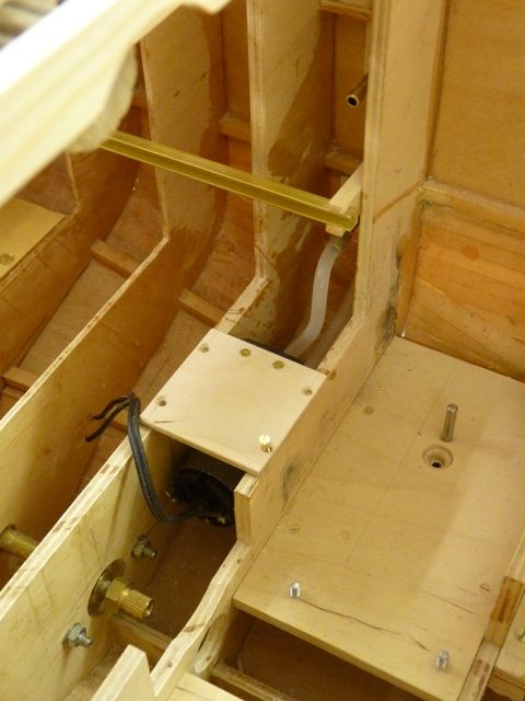
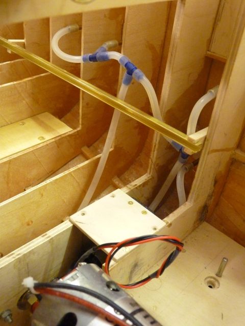
                                  The last couple of days has been spent fitting the water pump to dump water overboard from three outlets on the port side and one on the starboard. There is a single inlet to the pump mounted about 2 inches below the waterline.
                                   
                                  The pump is an MFA 650 gear pump which is self priming. It is mounted in the bottom of the hull, just behind the main motor and between two of the frames. Running on 12 volts it takes 0.65 amps but a lower voltage will probably be used to produce a more realistic flow and reduce the noise. The initial trial will be carried out using a slave speed controller but on Dave Milburn’s advice, an adjustable voltage regulator, available from MFA, will probably be used in the end.
                                   
                                   
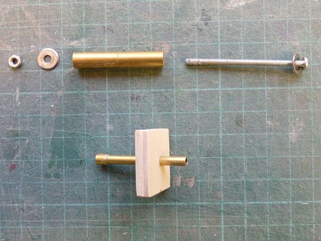
                                  All of the pipes through the hull are the same, made from 3/16 brass tube with a short length of slightly larger tube glued on the end to give the flexible silicone tubing a more secure grip. A piece of 6 mm ply was used to reinforce the area where the tube penetrates the hull. Each one was glued in place with araldite and a long setscrew and piece of larger diameter brass tube was used to clamp the assembly in place while the glue dried.
                                   

                                  Short lengths of silicone tubing and plastic tee pieces connect the system together.
                                   

                                  If the system works successfully during a trial later this week, I will tidy up the tube installation and secure the flexible tubing with tie wraps

                                  #32087
                                  Bob Abell 2
                                  Participant
                                    @bobabell2
                                    You are doing a splendid job there, young Gareth!
                                     
                                    Is the source water from possible leaks or just for effect?
                                    Most of my boats always leaked, so a pump was essential!…..and nice to see in operation too
                                     
                                    Bob
                                    #32088
                                    Gareth Jones
                                    Participant
                                      @garethjones79649
                                      Bob,
                                       
                                      The water system is purely for effect. If I had a leaky boat it would really annoy me. I suppose I could use the water flow to cool the motor but if you have to resort to water cooling on a boat like this it would really be an admission of failure.
                                       
                                      Gareth
                                      #32093
                                      Bob Abell 2
                                      Participant
                                        @bobabell2
                                        You may need a bilge pump, Gareth
                                         
                                        Knowing the unusual keel depth plus the lead ballast….The water is just waiting to get through that prop tube!
                                         
                                        Bob
                                        #32094
                                        Gareth Jones
                                        Participant
                                          @garethjones79649
                                          Ah but, ah but, ah but, I thought about that right from the start and fitted a Raboesch propshaft with a sealed bearing!
                                           
                                          Gareth

                                          Edited By Gareth Jones on 12/10/2011 18:29:08

                                          #32135
                                          Gareth Jones
                                          Participant
                                            @garethjones79649
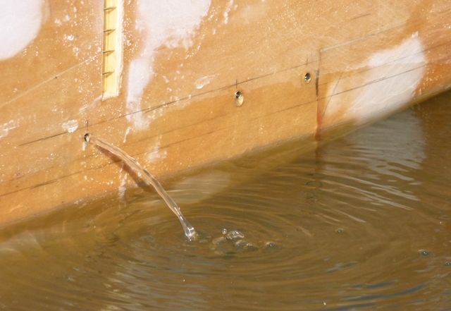
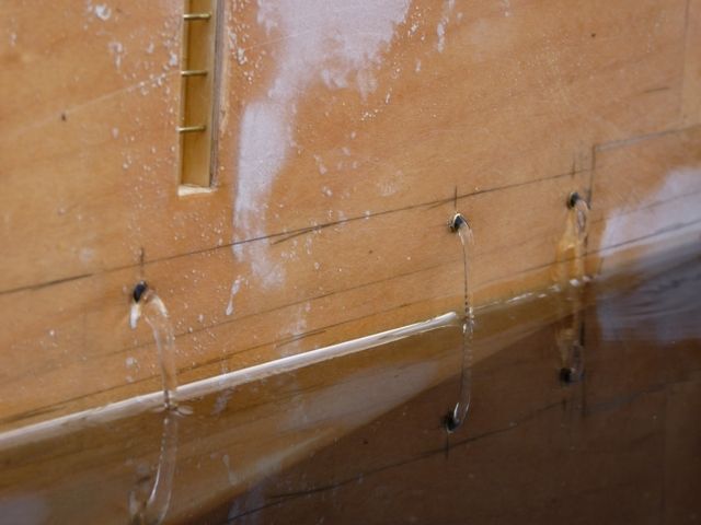
                                            The first tests on the simulated overboard water flows were very disappointing. At 12 volts, the pump motor was very noisy and I only got a flow from one of the outlets on the port side, nothing significant from the other 2 on that side or the one on the stbd side, see photo below.
                                             

                                            I tried adjusting the pipe layout to get a better balance of pressure drops to even up the flow but it was still not very good. I then replaced the piping with some silicone tubing from an old fish tank. This was slightly bigger bore and gave much better performance. The picture below shows the flows from the port side with the pump motor running on 7.2 volts and much quieter operation. Unfortunately the water does not scale very well and it looks a bit more ‘glassy’ than the real thing.

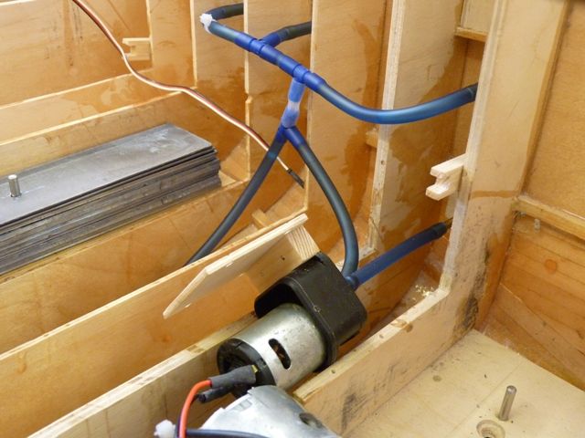
                                            The flow from the stbd side was comparable to the left hand outlet above so its seems reasonably well balanced and is ready for the piping to be tidied up. Heres a view of the final pipe layout before clipping. The pump is laid on its side just to give a clearer view.
                                             
                                             
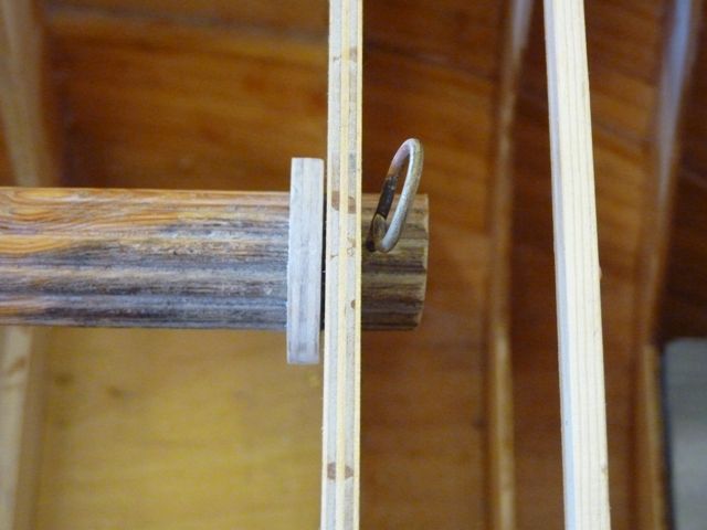
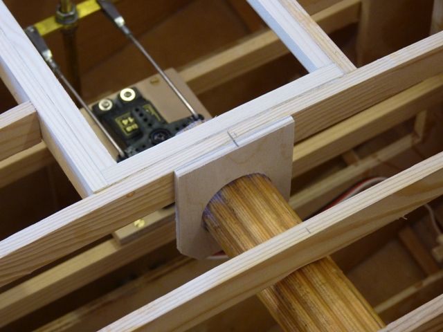
                                            I have also slightly modified the lifting handle. At the front end I have added a collar to act as a stop and a hole for a pin in front of the frame to prevent the handle sliding backwards and forwards when lifting the hull. The pin will be accessible through the hatch immediately in front of the wheelhouse.
                                             
                                             
                                            At the back end I have added a support plate with a hole in it so the handle can be slid backwards to leave the central access area completely unobstructed when required.

                                            The next major task is to fix the rear part of the deck so that I can build up the bulwarks around the sides and transom.


                                            Edited By Gareth Jones on 17/10/2011 19:04:59

                                            #32139
                                            Bob Abell 2
                                            Participant
                                              @bobabell2

                                              Hello Gareth

                                              The water flow through your pipe system needs to have….Flow control valves…..you can get them from the local pet shop

                                              These will control the flow through each pipe, and I think your pump may be a little small

                                              I did think about a central reservoir, with the three pipes coming from it?

                                              Bob

                                              #32155
                                              Gareth Jones
                                              Participant
                                                @garethjones79649
                                                Hello Bob,
                                                 
                                                I think my original pump gives enough flow when operating at 7.2 volts. I am not trying to simulate a jet of water from the side of the hull, just a gushing flow as shown in the photo of the real thing below. The problem is getting the white turbulent look – or maybe I am getting a bit obsessive now! Maybe I will add a bit of white paint with the odd bit of silver just below the outlets to add to the effect
                                                 
                                                 
                                                I have tried another pump today in the form of a Graupner 10 volt centrifugal pump. On paper it should produce about twice the flow but in reality I dont think there is much difference at the same voltage. Maybe the pressure delivered is lower than the original gear pump but it does have the advantage that it is much quieter. However after leaving it running for around 10 minutes at 7.2 volts it was getting pretty hot and, while the Graupner instructions don’t mention it, the Cornwall Model Boats website says its not recommended for continuous running. I think I will try the Graupner pump for the time being and just switch if off after a few minutes.
                                                 
                                                I have got a flow control device on one of the lines to the outlet in the stbd side. Its one of the clamp on restrictors from an old smoke system and seems to work OK by squashing the plastic pipe to a controlled degree. A reservoir might help a bit but the flow is smooth and steady now and it would only add yet more complication so I dont think I will bother.
                                                 
                                                Gareth

                                                #32166
                                                Dave Milbourn
                                                Participant
                                                  @davemilbourn48782
                                                  Gareth
                                                  You may best be advised to sit down when you check the prices, but these pumps are akin to those bits of a dog that your mother wouldn’t approve of……………….. http://www.micropumps.co.uk/
                                                  Dave M
                                                   
                                                  #32167
                                                  Gareth Jones
                                                  Participant
                                                    @garethjones79649
                                                    Dave,
                                                     
                                                    I have spent most of my budget on a noisy thing system, I cant afford much else. I did look at the micropump website over the weekend but I can’t justify that much money, even though they do look really neat little pumps.
                                                     
                                                    I am still eagerly awaiting an answer to my question on page 6 of this thread (although I do apologise for spelling your name incorrectly.) Is there any way you can slow down a servo in only one direction, eg by using a Servomorph somehow?
                                                     
                                                    Gareth
                                                    #32318
                                                    Gareth Jones
                                                    Participant
                                                      @garethjones79649
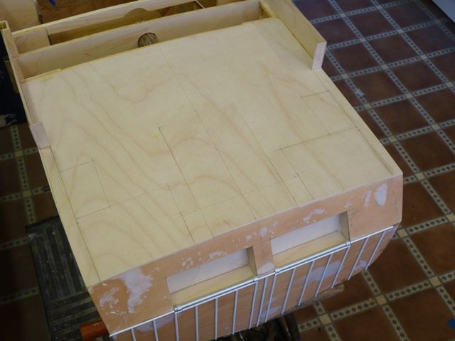
                                                      In the last week or so I have made a bit more progress with the deck and electrics. The rear part of the deck has been covered in 1.5 mm ply with a section removable over the rudder servo. I have started on the bulwarks around this part of the hull but the first attempt at the rear corners was not very good. These have a fairly small radius of around 8 mm so I am going to have a second attempt but this time steam some 1.5 mm ply to achieve the shape.
                                                       

                                                    Viewing 25 posts - 51 through 75 (of 371 total)
                                                    • Please log in to reply to this topic. Registering is free and easy using the links on the menu at the top of this page.

                                                    Code of conduct | Forum Help/FAQs

                                                    Advert

                                                    Latest Replies

                                                    Home Forums Scratch build Topics

                                                    Viewing 25 topics - 1 through 25 (of 25 total)
                                                    Viewing 25 topics - 1 through 25 (of 25 total)

                                                    View full reply list.

                                                    Advert

                                                    Newsletter Sign-up