The world's leading magazine for all model boating interests
Shemarah II
Shemarah II
Home › Forums › Scratch build › Shemarah II
- This topic is empty.
-
AuthorPosts
-
5 July 2011 at 22:10 #31243
Gareth Jones
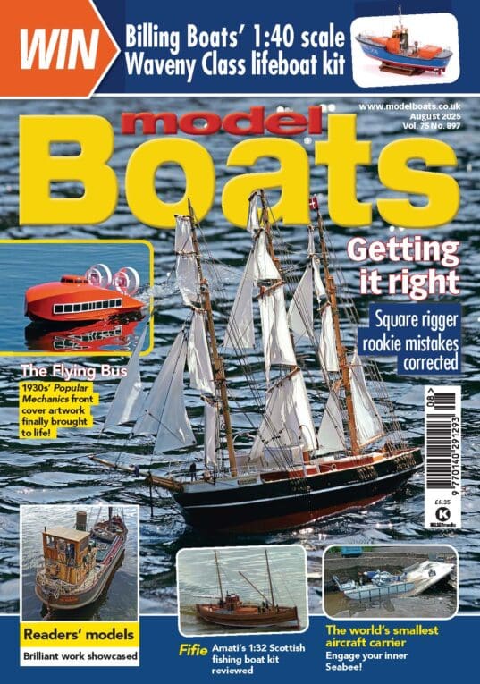
Participant@garethjones79649Thanks for that John, I have decided to go with the tissue rather than the glass cloth, which I have put back into my might come in useful one day cupboard.The last couple of weeks has seen the tops of most of the frames cut off at deck level just leaving 4 pairs to attach the hull back on the building board at the fibreglassing stage. The next task was to complete the hull skin up to the level of the bulwarks. I started by making a paper pattern of the bow section.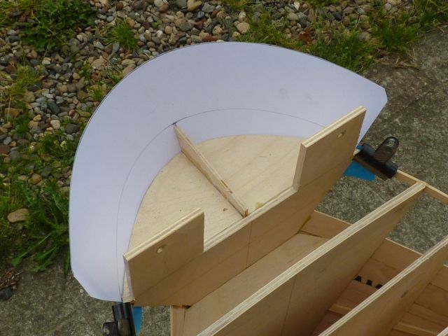 I then cut out a cardboard replica and finally a piece of 1/16 ply. I soaked this in near boiling water and then microwaved it for a few minutes before bending it around the bow section. I did eventually get it to fit reasonably well but it was going to be impossible to clamp it in position. The other drawback was the shape was not quite right. The stem of the real vessel has a slight curve, leaning further forwards at the top. However it was impossible to get this shape in the piece of ply as the curve around the stem was so tight, it was too stiff to bend in the other plane as well. I decided that it would be best to fix the side pieces of the upper hull skin which would give me more scope to clamp the bow piece afterwards.
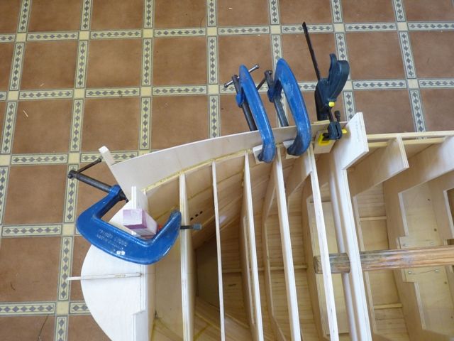 Again paper and cardboard patterns were made first and a piece of 1/16 ply cut to form each side. The front and rear edges were scarfed over a distance of about 15 mm to allow an overlap of the adjoining pieces. After the two forward pieces were fitted and glued the two side pieces were made and fitted the same way, again with a scarf on the leading edge to overlap the ajoining section.
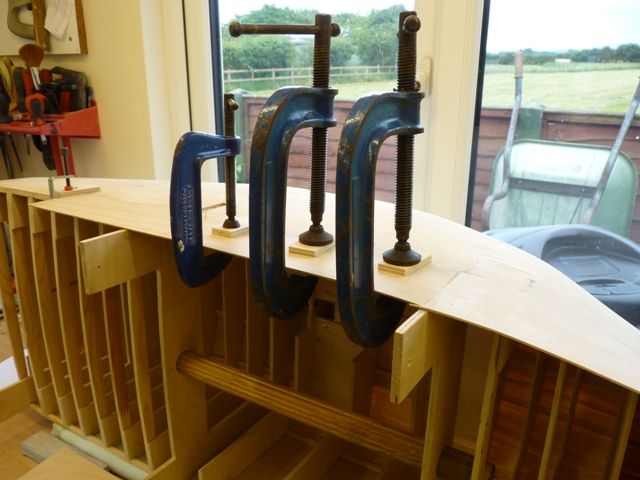 I decided to start again with the bow section and this time cut three pieces of 1/32 ply instead of one piece of /16, and these overlapped and were staggered so there are three layers over the top section, two over the mid section and one at the bottom. Each was glued on and allowed to dry before adding the next. Finally they were sanded to get a smooth finish with a slight curve to the stem as required.
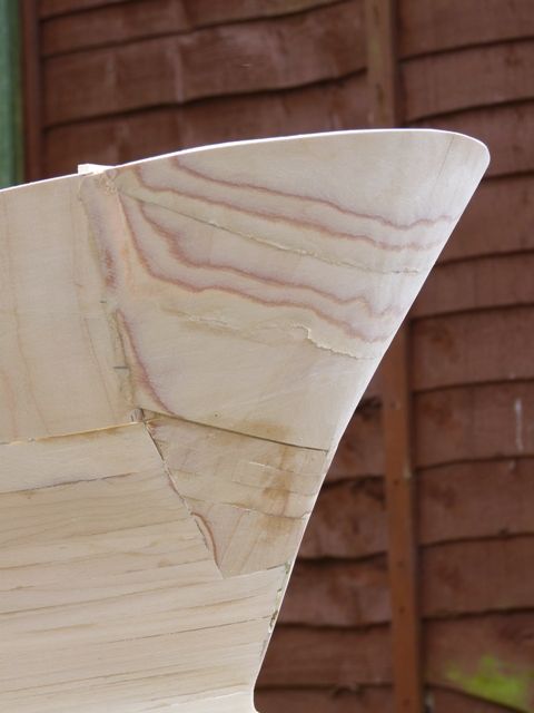 The top of the bulwark was trimmed to give the final height plus a couple of mm spare. When the deck has been fitted I will trim it back to the correct height all round.
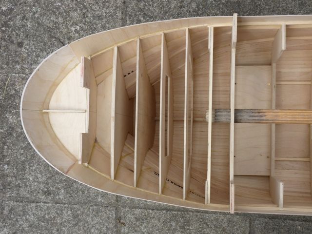 There is still a lot of sanding and profiling required in the bow area but its not far off ready for fibreglassing now, I have also added the top part of the transom with two holes cut for the doors. I have also cut away several of the aft deck beams and fitted the edges for a panel which will give me access to the rudder controls and servo.
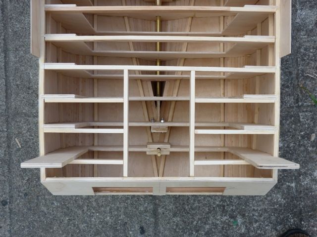 As a change from woodwork I have also started construction of the rudder. This is made from a piece of brass sheet, in fact its a door push plate from B and Q. Its a suitable thickness, just needs a bit of rubbing down to get the laquer off before soldering. A pice of rectangular brass strip 7 mm wide and about 2 mm thick was soldered on to each side of the rudder plate, after it had been cut out from the sheet.
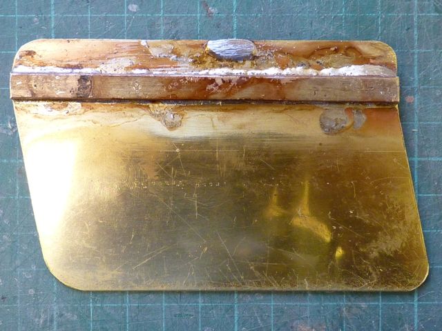 The top and bottom were drilled on my pillar drill to accept the rudder bottom pivot shaft and the top torque shaft.
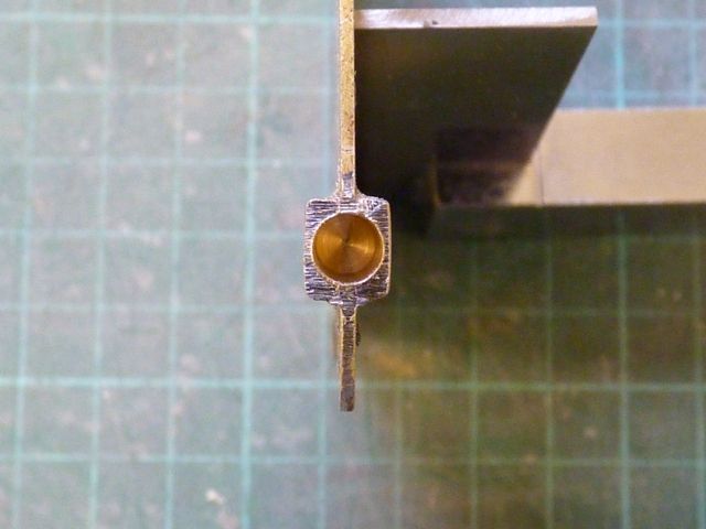 These were then cut from 7/32 brass rod and soldered in place with a couple of big G clamps to act as heat sinks.
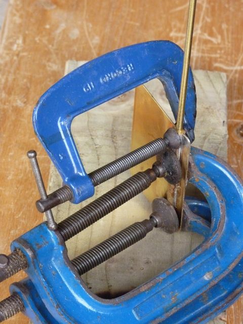 A piece of rectangular brass strip was attached to the skeg with two brass screws. This will support the bottom bearing of the rudder and the bottom of the Kort nozzle. I find this piece usually has to be removed and refitted lots of times which can result in the screw threads stripping in the wood. I initially use smaller screws to attach it to the skeg and fit longer ones when it is ready for the final fit.5 July 2011 at 22:21 #31244Participant@garethjones79649Heres a picture of the rudder and Kort nozzle fitted to the skeg. The bottom bearing was made from a short length of brass rod cannibalised from a stopcock and soldered on to the brass strip. The rudder pivot tube is made from 1/4 brass tube but the extension below the hull was again made from a piece of the stop cock. Since I don’t have a lathe, drilling concentric holes in brass tubing is pretty hit and miss but the end result was OK after throwing away a few failed attempts.
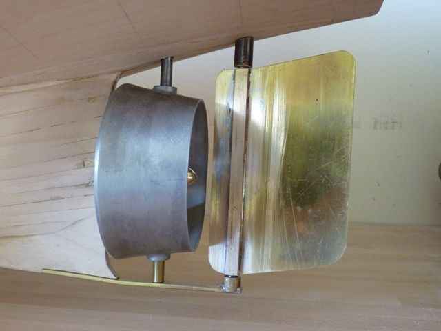 The real rudder has a number of stiffening ribs and these are going to be made from 1.5 mm thick styrene strip superglued on to the rudder. Here’s the first attempt cut out prior to sticking it on.
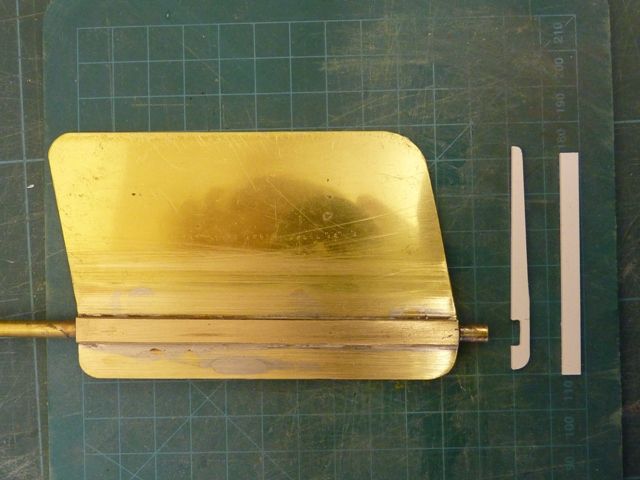 7 July 2011 at 21:20 #31263Participant@garethjones79649Back on the hull for a few days now, heres the final standard prior to the first coat of resin being applied.
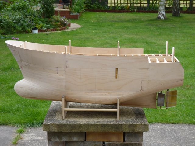 And here she is, taking in the rays in the back garden while the smell of the resin evapourates. The cut out area in each side where the steps are has been temporarily blanked off with a bit of scrap ply.
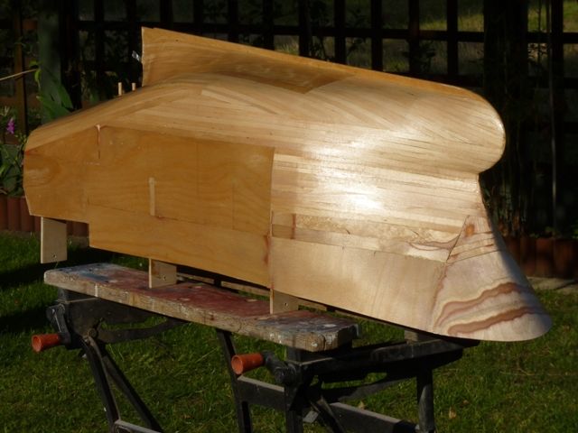 27 July 2011 at 08:57 #31398
Bob Abell 2
Participant@bobabell2Time for the latest update, Gareth?Bob27 July 2011 at 19:00 #31401Participant@garethjones79649OK Bob, its a bit subtle for me but was that a hint?Anyway here is a bit more about Shemarah but more along the lines of ‘Great Eastern the cable layer’ than ‘Shemarah the model’. I have always been fascinated by machines, the more complicated, the more interesting and I always like to try and understand how they work. A couple of years ago I built a Mountfleet Osprey armed drifter and there were two pieces of equipment fitted either side of the superstructure that I could not understand. They looked like old fashioned cast iron radiators but the drawing only showed one view of them, the instructions did not mention them and the photos were too small to see the detail. Eventually I found the magic word to type into Google which turned outo be Oropesa, the type of float used to suspend the end of the minesweeping cable. The ‘radiators’ turned out to be the kite and otter which were used to pull the front end of the cable down and rear end out sideways. Eventually I found suitable pictures of the real thing and was able to make a better model as a result. I also learned a lot about how minesweepers work, which is always useful when anyone askes me questions about the model. I suspect I may have fitted WW 2 kites and otters on a WW 1 minesweeper, but I am not too fussed about that. One thing I never did find out was how did they get the kites, otters and oropesa floats in and out of the water, there were no suitable davits or cranes on the model, was it just a case of manhandling them over the side or is there something missing from the model?However, back to Shemarah II, there are two similarly puzzling aspects of the real vessel which maybe someone can explain to me. She is a twin rig trawler and I can see how the three main winches will pull the trawl wires (warps?) and the power block on the rear gantry is presumably used to somehow haul up the net at the end. However, the cod end hatch is forward of the main superstructure on the starboard side. Presumably therefore each of the two nets has to be somehow manoeuvered around the side of the ship to get it over this hatch. I wonder how they do this. It seems a bit of an awkward layout but maybe some naval architect or fisherman can explain why the ship is laid out like this.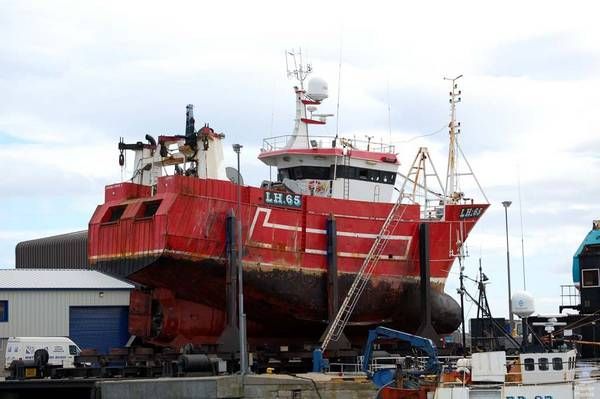 Secondly in the transom there are two large rectangular doors with a roller at the bottom edge, suggesting something is hauled into or out of this area. The net drums are up on the shelter deck above this, so I am puzzled about the purpose of the transom doors – does anyone know the answer, maybe Donald Moodie the skipper of Shemarah II could enlighten me.As far as the model is progressing I have spent the last couple of weeks filling and sanding the hull. Its just about ready for the application of the fibreglass tissue and resin, probably starting in the next few days.
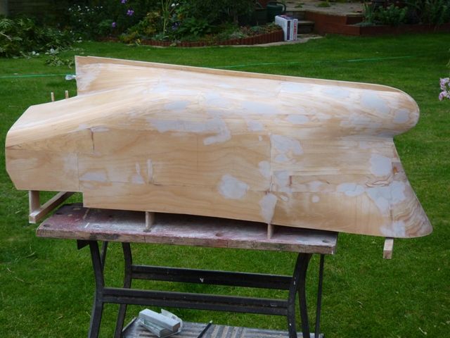 27 July 2011 at 20:43 #31402Participant@bobabell2Hello GarethAre you going to give the hull a scale appearance?……….Welded or rivetted plates etc?Bob27 July 2011 at 21:21 #31403Participant@garethjones79649Bob,I think rivets had gone out of fashion by 1995 when Shemarah II was launched and at a scale of 1:25 I dont think you would really be able to see the weld lines, so the answer to your question is probably not. From the photos I have of the vessel, the most obvious hull feature is the way the plating ‘pants’ between the frames but I cant see any way of reproducing that realistically on the model. There are lots of half round reinforcing bars to protect the aft end and I will be fitting those.Gareth30 July 2011 at 21:31 #31438Participant@garethjones79649I have had a look at some of my photos of Shemarah and in one of them which shows her on the ship lift at Fraserburgh you can see some weld lines so maybe I will add that detail after all. However I will need some better photos to get them all in the right place.I have now covered about 70% of the hull exterior in glass fibre tissue and learned a few lessons in the process. I found that the dosing ball from the top of Persil non bio washing liquid is a good disposable measure for the resin as its calibrated at 35 and 52 ml. Mixing up 35 ml is about the most I could cope with. I tried 52 ml and was left with a gooey lump in the bottom of my paper cup as it set before I could use it all. 35 ml of resin covers around one square foot of tissue so you have to work as quickly as possible in relatively small areas at a time. I used the minimum amount of hardener to get the maximum working time. I could tell when the resin was starting to get too tacky as the brush tends to start picking up fibres from the tissue and gets quite hairy. Dunking the brush in cellulosce thinners immediately after use seems to preserve it reasonably well. I’m still on the original brush but I wont be using it for painting in future.I tried wrapping the tissue around the keel but that did not work well at all as it inevitably pulled away on the inside corners leaving gaps underneath. I found the best method was to cover each side of the hull with separate pieces of tissue, starting by clamping the end of the sheet to the keel with bulldog clips and leaving about 1 cm spare on the edge. Resin is then applied to the hull to within about 1-2 cm of the keel and allowed to go off. The next lot of resin is then applied up to the keel and into the corner so that the tissue gets worked well into the corner. The photo below shows this stage of the process. Finally the top can be trimmed and folded over for the next application of resin.
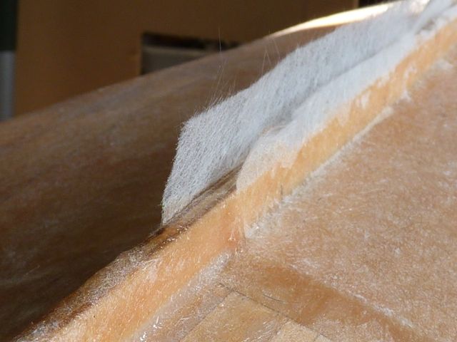 I think I will also apply some tissue and resin on the inside where the hull is planked rather than covered in ply sheet. In some areas on the corners the planks are pretty thin where they have been sanded and they could do with some reinforcement.I am going to apply two more coats of resin on the exterior and the comes the joy of several days sanding the hull to get the final smooth surface finish, and probably several more iterations of Isopon filling as well.31 July 2011 at 06:04 #31440Participant@bobabell2
Hello Gareth
I’m just wondering, how will you reproduce the welded seams?
Suppose a feint scratch mark would be ok….as long as they are dead straight?
Anything is better than a plain smooth hull!
Butt jointed card or litho might be ok?
Bob
31 July 2011 at 09:10 #31441neil hp
Participant@neilhpat that scale, Bob…..you wouldn’t see welded seams raised or indented, and anyway, on fishing vessels they were ground almost flat anyway to avoid snagging of the nets when hauling.even on rivited steam trawlers the rivets (except for thise on the stem and keelson) were all ground flush to avoid snagging of nets.31 July 2011 at 09:15 #31442Participant@bobabell2Thank you Neil…….That makes good sense!It`s just that I like to see some hull detail of sorts…..Especially rivets!Bob19 August 2011 at 08:55 #31588Participant@garethjones79649Not much visible progress over the last few weeks due to holidays and some major DIY work as a result of having a new central heating boiler and hot water cylinder fitted at home. Shemarah is now being rubbed down to achieve a good surface finish on the fibreglassed hull. This is going to take a while, there is obviously a knack to getting a smooth finish at the resin application stage which I dont seem to have. Its just a matter of plodding on using an electric sander where possible and wet or dry paper where not. I have found that the electric sander is best with a light touch to avoid the resin melting and clogging the paper. You have to be carefull on the corners so that you dont go completely through to the wood. Wet or dry paper used with some soapy water is best once the biggest lumps and bumps have been removed.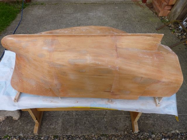
I guess there are another couple of weeks or so of this tedious job before I can move on to something interesting. However I can at least look forward to some retail therapy at the Birchwood show next weekend where I will be on the lookout for a sound system and some advice where to fit the speaker. I am also planning to work out how much half round styrene strip I need to make the reinforcing bars which cover the back end of the hull so I can aquire that – it may not be as exciting as rivets but it is hull detail to keep Bob happy.
19 August 2011 at 09:00 #31589Participant@bobabell2Thank you, GarethI have often wondered what those bars were for!Now!……..Don`t go to Birchwood next week……..As the show was cancelled months ago!The show has moved to Haydock!Bob19 August 2011 at 13:32 #31590Participant@garethjones79649Bob,I am no expert in marine engineering but I assume the half round bars are to protect the relatively thin skin plating from damage in the areas where the heavy weight bits of the trawling gear are hauled aboard. Nobody has told me what the two big doors in the transom are for yet.I know part of next weekends show is now at Haydock but I assume the smaller concurrent show is still at the Birchwood sports centre ( I never did understand the relationship between the two shows). I see guest of honour at Haydock is Paul Freshney, we had all better be on our best behaviour or there could be a big expose in a future Model Boats magazine.Back to the sander,Gareth19 August 2011 at 18:09 #31592 Colin BishopModerator@colinbishop34627I think Paul is very pleased to be guest of honour, he is a regular attender. Be sure to go and say hello won’t you!Colin19 August 2011 at 18:28 #31593
 John W EParticipant@johnweHi Gareth
better late than never as the saying goes – but try not to use a power tool for sanding the resin.As you have found out, it not only clogs the sand paper fast, but also what can happen is that you burn the resin and it can soften and weaken the molecules in the make up of the polyester resin. When this happens the resin will be soft for a time and can blister and peel off. To prevent this, the professionals use an open mesh diamond disc cutter and even these will clog up. If you go and get very coarse grit aluminium oxide abrasive paper from the auto cars stores and use this wrappedaround a block of wood, you will find this removes the lumps out of the resin quite quickly. Then you can finish off with the various grades of wetand dry.
As for putting the plastic halfround strips on the side of the hull – if you make yourself a couple of small templates up with the angles on and the right distance between the strips youwill find it helps to keep them parallel to one another. I also found that Gripsuper glue was the best for attaching them to the hull.
Hope this is of help
Aye
John
Edited By bluebird on 19/08/2011 18:29:22
Edited By bluebird on 19/08/2011 18:30:34
19 August 2011 at 18:51 #31594Participant@garethjones79649Thanks for that John,I think I will abandon the power sander and just do the job by hand.What is slightly more worrying is that there are quite a few small areas where there has been an air bubble in the resin/tissue layer and these are now coming to the surface leaving a crater. The question is do I keep sanding till I reach the bottom of the crater or just leave them with a reasonable resin layer around them and fill the crater afterwards?I am a bit concerned about water getting under the resin in these areas.I will follow your advice on the strips when I finish rubbing down the hull (if I ever do)Gareth19 August 2011 at 18:58 #31595John W EParticipant@johnweGareth hi ya
If you prick out and open up the small air pocket holes in the resin, and then fill them with car body filler – then sand them back – this will solve the problem of any water getting in. If you do by any chance sand through the fibre glass, back into the timber, what you can do is recoat that timber with resin and then lightly sand, knowing that you are very close to the timber area. I have, myself, done this on one or two models in the past. I have been trying to download photographs of when I built the Sea Lady, but if you go onto Model Board Mayhem and type in Sea Lady in the search, you will see the full build on there.
She has a similar hull to the one you are constructing.
http://www.modelboatmayhem.co.uk/forum/index.php?topic=28028.0
KEEP ON THE GOOD WORK MY MATE – it is really looking nice.
aye
john
Edited By bluebird on 19/08/2011 19:04:44
Edited By bluebird on 19/08/2011 19:05:26
19 August 2011 at 19:06 #31596Participant@garethjones79649Thanks for that John,it seems like a good plan.Gareth20 August 2011 at 08:04 #31599Participant@bobabell2Hi GarethWhat do you think of this suggestion?Seal the hull as it is at present…..Forget all that crazy sanding!Cover the hull with plates, edge butted, made from beer can aluminium or card?Just a suggestion…………Bob20 August 2011 at 09:35 #31600Participant@garethjones79649Hi Bob,I am not keen on the idea of plating the hull, its yet another step into the unknown and I dont think it will give the look of an all welded ship. I think I will stick with the sanding block for this one – better the devil you know.I have the Spurn lightship pencilled in as a possible future project. That’s got lots of joggled and rivetted plates and might be the test bed for your suggestion. You will probably have to wait till around 2013 before you see any results though.RegardsGareth25 August 2011 at 21:18 #31652Participant@garethjones79649After a few more hours work one side of Shemarah’s hull is now sanded down and filled where necessary.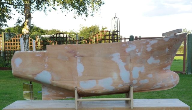 Hopefully the other side will be quicker, and no doubt after the first coat of primer lots more areas will be revealed as needing filling, but thats normally the case.As a bit of light relief I have made the rudder servo mount and linkage today. The servo is mounted on a piece of 6 mm ply which will be screwed to two cross beams. These are 12mm x 6 mm pine strips which run the full width of the hull and will be glued to the frame webs at a suitable height. Nothing has been fixed yet, the beams are just clamped in place. The rudder servo is a Futaba S3014 high torque servo. A standard servo would probably be OK. I just happen to have this one going spare at the moment and its the same size as a standard servo if I decide to pinch it for some other application later.The rudder pivot tube has been made long enough so that the top is above the water level to minimise the risk of water seeping up into the hull by that route. I like to use a push-pull double linkage for rudder controls as it give some degree of dual redundancy and it minimises the side loads on the rudder. In most cases its easy enough to engineer it into the space available.
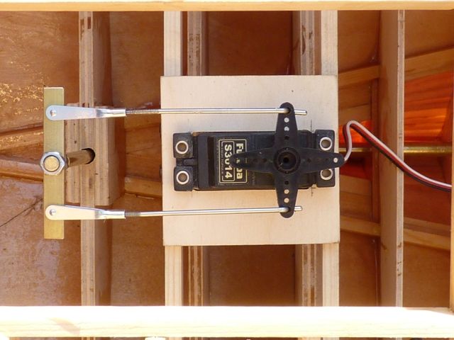
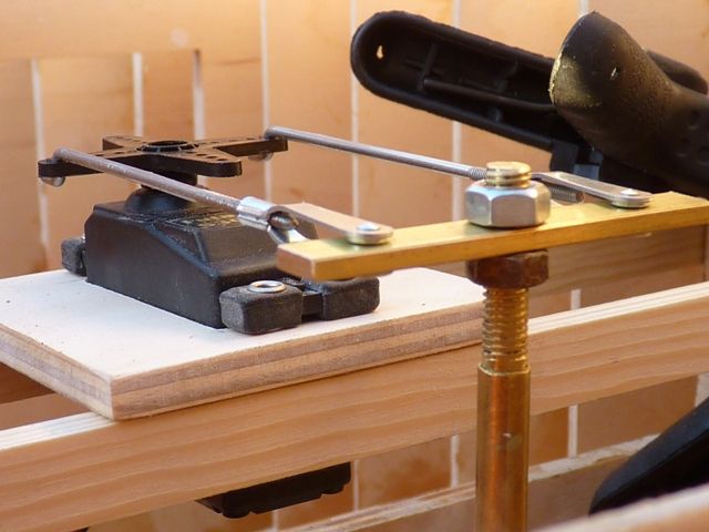
In the final installation I will have a plain washer under the bottom nut which will rest on the rudder pvot tube, and a couple of spring washers either side of the pivot lever which was made from a bit of brass strip.
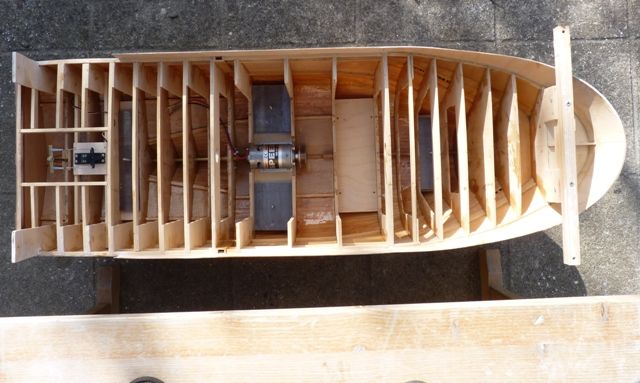
8 September 2011 at 20:56 #31762Participant@garethjones79649Its been a while since I updated the build log for Shemarah but don’t despair I have not been defeated by sanding down the fibreglass resin. That job is now just about complete with just a few minor spots to fill and sand. I will probably have one more round of filling and sanding before the hull will be ready for the next stages prior to priming.After some consideration at the Haydock Park model boat show I decided to purchase an Action Electronics Noisy Thing sound system and after discussion with Dave Milburn the speaker will be mounted in the floor of the superstructure and be removed with it. This leaves the interior layout free for all the rest of the gubbins, by far the heaviest of which will be the ballast. There is some confusion between the Model Boats article on Shemarah and the plans. The editors note in the article says the model should weighh 19.6 kg, whereas the plan says 31.4 kg.The full size vessel displaces 301 tons or near enough 301,000 kg. The model is to a scale of 1:25 on linear dimensions. The scale factor for any area is therefore 1:25 x 25 or 1:625. The scale factor for any volume is 1:25 x 25 x 25 or 1:15,625. Since the model must float at the same waterline as the real vessel it must therefore displace proportionally the same volume of water. The weight of the water displaced by the real vessel is 301,000 kg therefore the weight of water displaced by the model (and hence the weight of the model) must be 301,000 / 15,625 = 19.26 kg. One up to Paul Freshney there then.There has been some scepticism about operating a boat of this weight, 19.26 kg is around 43 lb. My plan has always been to move the model using a build in handle and fit the superstructure when it is on the water. To test this theory Shemarah was ballasted up with 7 house bricks and weighed on the bathroom scales at 46 lb. Just to satisfy myself it is going to be possible to lift it, and the handle is not going to break, heres a photo of the model, and my arm being tested.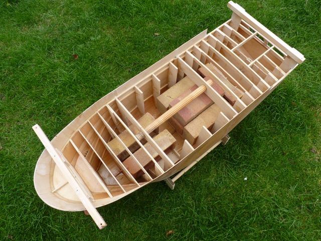
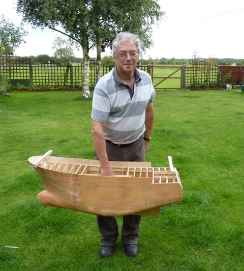
Its heavy, but its much easier to lift and lower into the water with a handle in the centre than trying to hold on to the outside of the hull. On the basis of this test I have decided to follow my original plan.
8 September 2011 at 21:20 #31765Participant@garethjones79649Having made the decision to go with the original plan of lead ballast and not try and complicate things with a pumped water system, I have now installed the ballast supports. There will be 4 main areas of ballast. There are 2 pads, one either side of the motor mount which will probably take the biggest proportion of the ballst. The hull currently weighs around 5 kg and that will probably double when all the rest of the model is added so I guess I will need around 10 kg of ballast. I guess around 3 kg will go either side of the motor mount and 2 kg at either end of the centre section.The ballast mounts were made from 6 mm ply which is screwed on to 10 mm square pine bearers which in turn are glued to the internal frames. The photos below show the 4 areas and a typical pad. A single 4 mm screw has been fitted in the centre of each pad to act as a stud which will retain the ballast. Individual sheets of lead will be added in all 4 positions to get the boat level at the correct waterline. Around 17 will be needed either side of the motor to give a total weight of 6 kg here. ( I weighed one of the initial cut sheets on the kitchen scales) I have used this method on other models and it works quite well allowing accurate balancing to be achieved by juggling the size and number of lead sheets in each location. My source of lead sheet is the remains of a roll of lead flashing, originally purchased about 15 years ago to repair our roof valleys. There will be plenty left, even after Shemarah is finished.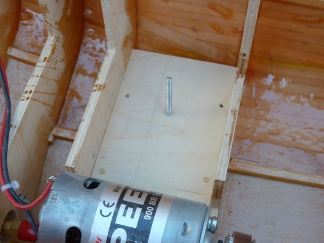
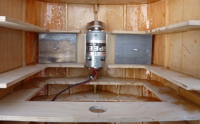 The aft ballast pad is shown in the photo below with the rudder servo mount which has also been fitted in its final place. While the front and rear ballast would not be so easy to fit while the boat is in the pond, the two centre blocks and the battery will be accessible so it should be possible to reduce the weight of the hull to around 12 kg if needs be, when I get old and infirm and can’t shift the complete hull.
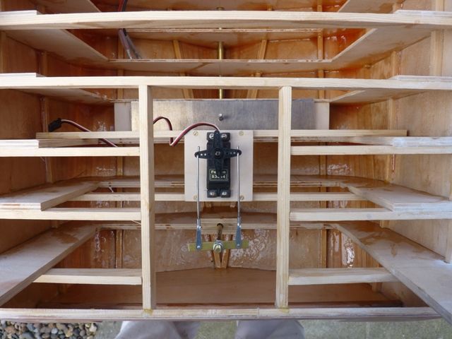 The planned next step is to fit the kort nozzle and propeller and temporarily install the radio and speed controller so that the whole of the propulsion system can be tested. I will have to cut quite a few more ballast weights to make the overall weight reasonably realistic then its off to the pond to see if the model performs OK in the water before proceding too much further.14 September 2011 at 20:18 #31797Participant@garethjones79649The last couple of days have been spent making the bilge keels. These are not shown on the drawings but can be seen on the photos of Shemarah on the ship lift. I have been fortunate to get some high definition pictures from Kevin Munro via the Trawler Pictures website. One of these shows a square on side view that allowed me to estimate the size and postion of the bilge keels.I started by attaching a piece of card to the hull using bluetack and masking tape and measuring from its edge to the hull at 20 mm intervals
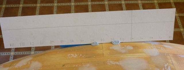 I then transferred these measurements to the card to get the actual profile of the hull and cut along this line.
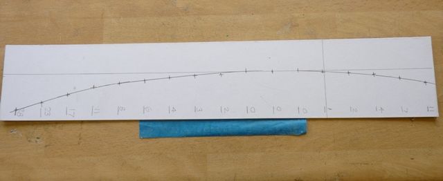 I the used this as a template to cut the bilge keel from 1,5 mm ply. I had to trim the edge several times and trial fit the keel to the hull to get a good fit. The keel and hull were both marked to ensure the piece was fitted consistently in the same place.
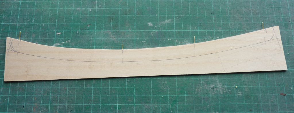 Four 1/32 holes were drilled in the keel to line up with the frames in the hull and 1/32 brass wire inserted in the keel. To allow the keel to be fitted to the hull, which is curved in 3 dimensions. its necessary to try and ensure all 4 pins are parallell, and the holes in the hull are at the correct angles. The keel was then trimmed to the correct width and length.
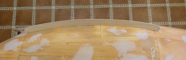 Both keels have been trial fitted and given a coat of resin prior to gluing them on with araldite tomorrow.
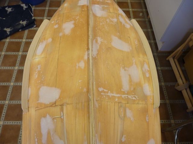
Because my working stand fitted the whole profile of the underside close to the ends of the bilge keels I have had to cut away sections from the stand so that there is no chance of trapping the bilge keels on the stand – a piece of 1.5 mm ply is not going to survive trying to support 20 kg of boat.
AuthorPosts- Please log in to reply to this topic. Registering is free and easy using the links on the menu at the top of this page.
Code of conduct | Forum Help/FAQs
Latest Replies
Home › Forums › Scratch build › Topics
Viewing 25 topics - 1 through 25 (of 25 total)-
- Topic
- Voices
- Posts
- Last Post
-
-
TID steam tug 42″ – PN Thomas drawing enlarged
1
2
Started by:
 Ray Wood 3
in: Scratch build
Ray Wood 3
in: Scratch build
- 8
- 39
-
12 hours, 3 minutes ago
Anthony Shilson
-
Vic Smeed’s Silver Mist
1
2
…
33
34
Started by:
Bob Abell 2 in: Scratch build
- 5
- 842
-
1 day, 10 hours ago
 Chris Fellows
-
4D Modelshop
Started by:
Keith Long in: Scratch build
- 6
- 10
-
5 days, 7 hours ago
 Colin Bishop
-
On the river
Started by:
Tim Cooper in: All things floating
- 3
- 3
-
6 days, 8 hours ago
 Richard Simpson
-
Triple-Screw Boat in River in Boston
Started by:
Queequeg Quint in: All things floating
- 4
- 7
-
6 days, 12 hours ago
Richard Simpson
-
Eezebilt RAF Fire Boat
Started by:
- 5
- 10
-
1 week ago
 ashley needham
-
Todays Boating
1
2
…
210
211
Started by:
ashley needham
in: All things floating
- 84
- 5,253
-
1 week ago
ashley needham
-
Triple Screw Boat
1
2
Started by:
- 11
- 44
-
1 week, 1 day ago
-
Aeronaut Mahogany Sheet issue
Started by:
floatmeboat2025 in: Beginners
- 4
- 9
-
1 week, 2 days ago
Colin Bishop
-
Lead Zinc boat parts Clean up, and Type of Glue to attach them
Started by:
bruce dixon in: Building Kits
- 3
- 5
-
1 week, 3 days ago
-
Antique model lifeboat
Started by:
douglarse in: Gallery
- 3
- 8
-
1 week, 3 days ago
Richard Simpson
-
Antique lifeboat in auction
Started by:
- 1
- 1
-
1 week, 3 days ago
-
Melton & District Model Club 60th Anniversary Model Show
Started by:
Michael Campbell 2 in: Shows and Events
- 1
- 1
-
1 week, 5 days ago
-
Fairey Huntsman 28
1
2
…
7
8
Started by:
Chris Fellows
in: Build Blogs
- 2
- 197
-
1 week, 6 days ago
Colin Bishop
-
Building a hull.
Started by:
 mick east
in: Scratch build
mick east
in: Scratch build
- 7
- 16
-
2 weeks ago
mick east
-
Fairey Faun
1
2
3
Started by:
Chris Fellows
in: Build Blogs
- 7
- 60
-
2 weeks, 1 day ago
Ray Wood 3
-
superglue allergy
Started by:
 Alasdair Allan
in: All things floating
Alasdair Allan
in: All things floating
- 5
- 12
-
2 weeks, 2 days ago
-
Model Yacht Racing – The future ??
Started by:
Ray Wood 3
in: Sailing Models
- 4
- 4
-
2 weeks, 2 days ago
Richard Simpson
-
Vic Smeed’s Legacy
Started by:
Colin Bishop
in: All things floating
- 6
- 15
-
2 weeks, 3 days ago
Colin Bishop
-
Feathered Friends
Started by:
Chris Fellows
in: Soapbox
- 3
- 9
-
2 weeks, 3 days ago
Richard Simpson
-
Fairey Huntsman 31
1
2
…
5
6
Started by:
Chris Fellows
in: Build Blogs
- 14
- 139
-
2 weeks, 6 days ago
Chris Fellows
-
John Cobb’s Crusader
1
2
…
7
8
Started by:
 Paul T
in: Scratch build
Paul T
in: Scratch build
- 1
- 192
-
3 weeks ago
 John W E
-
Complex Automata
Started by:
Colin Bishop
in: Soapbox
- 1
- 1
-
3 weeks, 1 day ago
Colin Bishop
-
RAF Fireboat ID
Started by:
 Dave Reed
in: Collectors’ corner
Dave Reed
in: Collectors’ corner
- 8
- 24
-
3 weeks, 2 days ago
-
Lady of Skye (puffer)
1
2
Started by:
mick east
in: Build Blogs
- 9
- 43
-
3 weeks, 3 days ago
Richard Simpson
-
TID steam tug 42″ – PN Thomas drawing enlarged
1
2
-
Viewing 25 topics - 1 through 25 (of 25 total)Latest Issue
Newsletter Sign-up