Receiver Controlled switch

Advert

Receiver Controlled switch

Home Forums R/C & Accessories Receiver Controlled switch

  • This topic is empty.
Viewing 14 posts - 1 through 14 (of 14 total)
  • Author
    Posts
  • #5374
    Chris Hoverd
    Participant
      @chrishoverd48135

      Help please!

      Advert
      #58708
      Chris Hoverd
      Participant
        @chrishoverd48135

        Hi all, I'm after some help with a Turnigy receiver controlled switch that I want to install. Basically the main power supply for the model is 12v, with the speed controller having a BEC obviously supplied by the main battery. Now I have installed a 6v lighting circuit. I bought the receiver controlled switch and followed the installation to the book. The switch is wired in the positive wire coming from the 6v battery, through the load (12 grain of wheat bulbs) and returns to the negative side of the 6v battery. Much to my surprise, it doesnt turn the lights on and off. After much head scratching and research, I discovered that the switch unit needs a common return to work. Because the unit is being supplied from the BEC on the speed control (12v) does this mean that the negative wire from the load has to be connected to the negative post on the 12v battery? Even though the supply battery is 6v and the GOW bulbs are 6v? That doesn't make sense to me and sounds like a recipe for disaster to me! 😬 Any help regards this would be greatly appreciated!

        Chris

        #58714
        Dave Milbourn
        Participant
          @davemilbourn48782

          Effectively you need a common ground (value) for the two power supplies, so the two negative battery terminals need to be connected. My approach to wiring diagrams is "if they do it like that then that's the way to do it". I wish some folk would regard my own diagrams the same way!

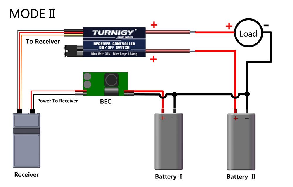
          Here is the Turnigy diagram. For 'BEC' you can substitute 'ESC'. BTW Battery #2 is the 6v one in your installation. I bet you use a relay switch next time – they aren't polarity sensitive and the load supply is completely isolated from the receiver/switch supply.

          e-switch.jpg

          Dave M

          Edited By Dave Milbourn on 25/06/2015 09:39:01

          Edited By Dave Milbourn on 25/06/2015 09:44:46

          #58715
          Chris Hoverd
          Participant
            @chrishoverd48135

            Dave to the rescue AGAIN! 😆

            I'm still a little confused though😬.

            In essence I need to bring 2 wires off the negative terminal on the 6v and connect one to the load and one to the negative side of Battery 1 (12v)

            And yes, I think there is a much better way of doing this! I will look into the relay switch option! 😆

            #58716
            Dave Milbourn
            Participant
              @davemilbourn48782

              Chris

              In essence I need to bring 2 wires off the negative terminal on the 6v and connect one to the load and one to the negative side of Battery 1 (12v)

              Yes. The drawing is correct. Make it look like the drawing and it will work. Trust me even if you don't trust Turnigy (help me out here, Malcolm). Just try it and see, OK? I could explain why but it would take a lot of words and you'd be no better off knowing the reason anyway. There are two articles here about electronic switches – in particular relay-based ones. **LINK**

              Dave M

              #58717
              Chris Hoverd
              Participant
                @chrishoverd48135

                Excellent thanks again! It just makes me a bit uneasy linking two different battery voltages together but I trust your many years of experience 😀.

                Ive got to admit this is my first experience of a Turnigy product and I'm not overly impressed.

                Thanks for the link, I will go explore! 😀

                #58719
                Malcolm Frary
                Participant
                  @malcolmfrary95515

                  You can hook as many batteries of differing voltage as you like to a common ground line (usually the negative these days, but in the olde days you got batteries both sides of the line) and there will be no problems until you start having bits of circuit connecting the different voltages. This should not happen.

                  Relay based systems do have the great virtue that whatever their contact(s) are controlling, the power supply can be totally independent of the model's radio power supply. The connection is just aux battery terminal to relay contact, then other relay contact to one side of load, other side of load to t'other battery contact.

                  I've had one or two Turnigy products, and they have all done "what it says on the label" and done it well, but there have been obvious economies when it came to writing the instructions in Engrish. Fortunately, the symbols and conventions of electronic circuits are fairly universal, so diagrams don't suffer from translation as much as the written word.

                  Semiconductor switches do need to be treated with caution as there are so many possible combinations , each with their own virtues and pitfalls. Like Dave says, make your wiring look like their drawing, it will work. Before you can think outside the box, in cases like this, you need to really know what is inside the box.

                  #58720
                  Dave Milbourn
                  Participant
                    @davemilbourn48782

                    The problem with technical instructions written and then translated is two-fold:

                    1. They are written by a technical person who already understands in detail how the thing works. It's difficult for him/her to overcome the fact that the reader does not have the same basic technical background i.e. the tendency is to think that writing 'simple' instructions is somehow patronising or even arrogant; and

                    2. The translation is done by a non-technical person. I once remember the word "cement" – as in balsa cement – being translated into the French for "concrete"……………….

                    This is why a diagram is worth a thousand words. It's a picture, and pictures don't need any words. Just print out Malcolm's last two sentences in large capitals and stick the print to your workshop wall.

                    Dave M (and thanks, Malcolm!)

                    #58722
                    Chris Hoverd
                    Participant
                      @chrishoverd48135

                      Excellent advice both! Thanks again 😀

                      #58723
                      Paul T
                      Participant
                        @pault84577

                        The problem with technical instructions written and then translated is two-fold:

                        1. They are written by a technical person who already understands in detail how the thing works.

                        This is why you should never buy a wife from Thailand surprise

                        #58728
                        harry smith 1
                        Participant
                          @harrysmith1

                          I sat and read an installation document for an alarm system and after getting to chapter 17, it explain the installation proceed.

                          This was another long affair and after installing the first alarm system.

                          I made up my own install manual (2 pages, step by step).

                          Gave it to another tech. and told him to go and install one.

                          His only complain was grammar and a spelling mistake.

                          The system worked first up!!!

                          #58729
                          Dodgy Geezer 1
                          Participant
                            @dodgygeezer1

                            Without knowing the switch, it sounds as if it uses the circuitry described below. I have made several of these – they work very well. Read the link to see why the negatives need connecting together…

                            **LINK**

                            #58731
                            Malcolm Frary
                            Participant
                              @malcolmfrary95515

                              Dodgy's link has a good example of electronic diagram symbols being ALMOST universal. He who drew it used the wrong symbol for the output transistor, showing a bipolar type rather than the MOSFET stated. I can sympathize, because I find bipolars easier to draw and remember things about. but for a home builder, this sort of thing can lead to pins being connected in the wrong order, which would not be good. Hopefully, the layout drawings have it right.

                              #58739
                              ashley needham
                              Participant
                                @ashleyneedham69188

                                I have recently installed a Turnigy remote switch in the hovervan, wired as instructed.

                                What I failed to recognise was the delay of a few seconds between operating the switch with the appropriate Transmitter lever and the actual operation of said switch. Made even longer as I was using the 5th channel in my Planet T5 set which is set to "soft start" caused me a few minuted of head scratching as it did and didnt work as I was twiddling the switch and checking connections….

                                Ashley

                              Viewing 14 posts - 1 through 14 (of 14 total)
                              • Please log in to reply to this topic. Registering is free and easy using the links on the menu at the top of this page.

                              Code of conduct | Forum Help/FAQs

                              Advert

                              Latest Replies

                              Home Forums R/C & Accessories Topics

                              Viewing 25 topics - 1 through 25 (of 25 total)
                              Viewing 25 topics - 1 through 25 (of 25 total)

                              View full reply list.

                              Advert

                              Newsletter Sign-up