Plans without hull lines

Advert

Plans without hull lines

Home Forums Scratch build Plans without hull lines

  • This topic is empty.
Viewing 15 posts - 1 through 15 (of 15 total)
  • Author
    Posts
  • #85667
    don steadman
    Participant
      @donsteadman41164

      I have aquired some ship plans which have a scale but no hull lines on them. Is there a given formula to get the hull lines from the plan? Thanks

      Advert
      #7166
      don steadman
      Participant
        @donsteadman41164

        Is it possible to build a boat without hull lines?

        #85669
        Chris Fellows
        Participant
          @chrisfellows72943

          In a word no, unless anyone else knows better.

          If you have a top and side view and there is a chine with fairly straight sides and bottom to the hull it is pretty easy to draw up the bulkheads/frames.

          But as you say it is ship plans this probably isn't the case and there will be compound curves to the hull and no easy reference points to pick up.

          I had a similar problem with a future build and overcame the issue by finding a boat with a similar hull shape and also studying photographs of the boat and drawing them out until I was happy with the design.

          I haven't used one but there are 3D modelling programs e.g. for model aircraft that make this process easier but you do need some idea of the lines.

          It would be useful to see the plans.

          Chris

          #85722
          Bob Wilson
          Participant
            @bobwilson59101

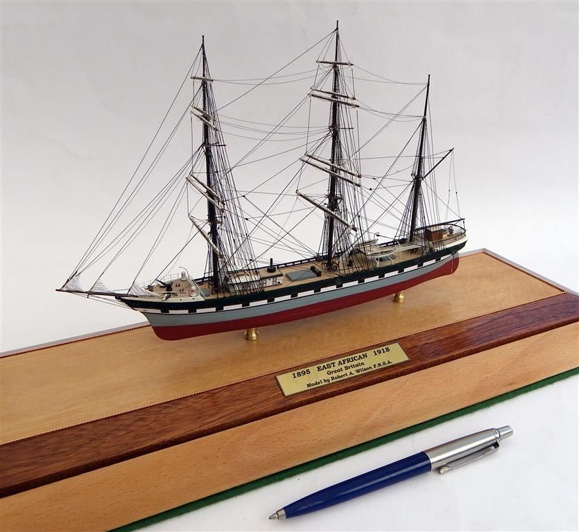
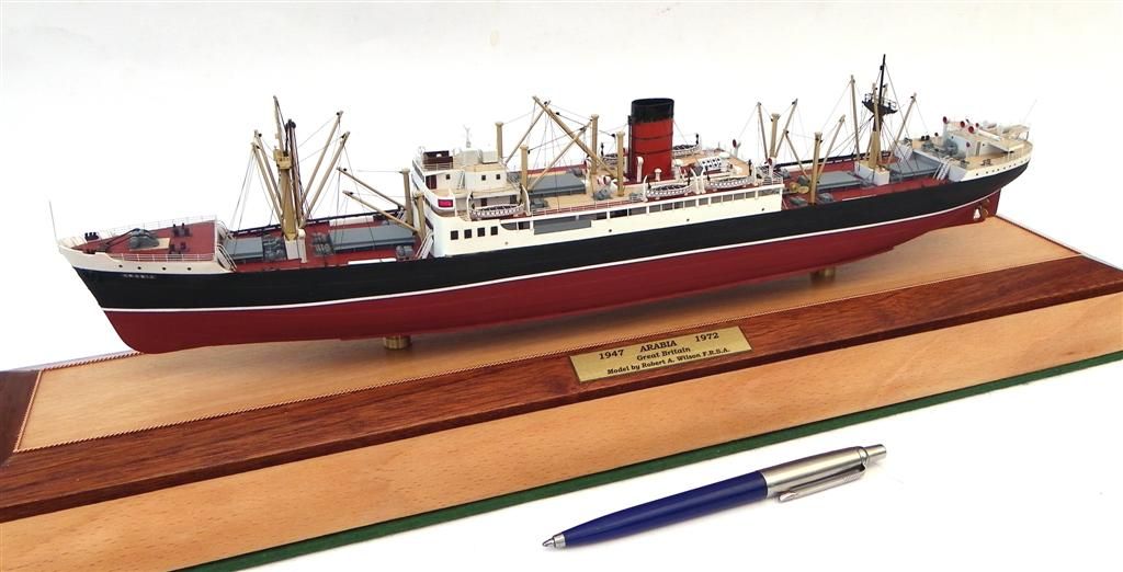
            If you are talking about ship plans, rather than boat plans, they often have the shapes of the lower decks on the general arrangement plan, and a good idea of the lines can be built up from them. I seldom find lines plans for whatever I want to build, but never have any real problems with figuring the shape out from the GA plan of the lower decks.

            Bob

            east african complete.jpg

            arabia out of case (large).jpg

            #85724
            Ray Wood 3
            Participant
              @raywood3

              Hi all,

              Sadly no further post from Don to give us a clue which ship he has the plans but no lines 😢,

              Regards Ray

              #85725
              Bob Wilson
              Participant
                @bobwilson59101

                It does help to have the name of the ship!laugh

                Bob

                #93810
                trevor hughes
                Participant
                  @trevorhughes84733

                  Has Anybody got any information on the profile stations on the Vic Smeed plan Hunt class destroyer C60?

                  The plan from Sarik does not show the positions of the profiles but does show the half profiles.

                  I want to build L34 HMS Bicester, as I grew up there (Bicester the town not on the ship)

                  Trevor

                  #93812
                  Ray Wood 3
                  Participant
                    @raywood3

                    Hi Trevor,

                    Vic Smeed was a methodical draghtsman, I'd divide the length of the hull by the number of cross sections you have and post a photo ? to be fair some designs reduce the spacing at the bow and stern as the hull shape gets more interesting, flared, curved etc. Let us know how you get on

                    Are the sections through the hull positioned on the drawing under the general arrangement side view ?

                    Regards Ray

                    Edited By Ray Wood 2 on 16/02/2021 08:30:48

                    #93814
                    Colin Bishop
                    Moderator
                      @colinbishop34627

                      Yes, I would be very surprised if Vic has shown the half sections but not their positioning.

                      Colin

                      #93821
                      trevor hughes
                      Participant
                        @trevorhughes84733

                        Colin

                        The trouble is the plan has been copied/scanned into a computer and then Digitally "cleaned". This is why I think there are no station lines for the half sections.

                        Ray

                        The sections are in the top righthand corner of the plan.

                        I think I can get most of the positions by measuring the sections and then from the centre line on the plan. The five midship sections have only minor differences in the bilge curves so spacing them equally should be OK.

                        But I will do a cad drawing to check that the waterlines don't have any obvious bumps or dips! !.

                        I know it sounds like I already new the answers but I was hoping to avoid the work if somebody already had a drawing.

                        Trevor

                        #93823
                        Ray Wood 3
                        Participant
                          @raywood3

                          Hi Trevor,

                          Save the extra time ! splash the cash and buy the drawing from SARIK ? may save in the long run

                          Unless your building at a different scale ?

                          Regards Ray

                          #93824
                          Colin Bishop
                          Moderator
                            @colinbishop34627

                            Your method should work.

                            Colin

                            #93829
                            trevor hughes
                            Participant
                              @trevorhughes84733

                              Ray

                              I did get the plan from Sarik. That's the one I'm using.

                              Colin

                              Thanks to Ray's knowledge of Vic's draughtsmanship I have started to draw the hull lines out. After drawing the side profile of the hull and placed the No.1 and No.11, I then marked all the rest at equal distance spacings and half spacings for 10.5 and 1.5. The deck sheer lines are smooth. And so far the waterlines, deck and diagonals look OK. So everything looks like it will be fine.

                              Trevor

                              #93830
                              Colin Bishop
                              Moderator
                                @colinbishop34627

                                Excellent!

                                Colin

                                #95707
                                Richard H Dunn
                                Participant
                                  @richardhdunn

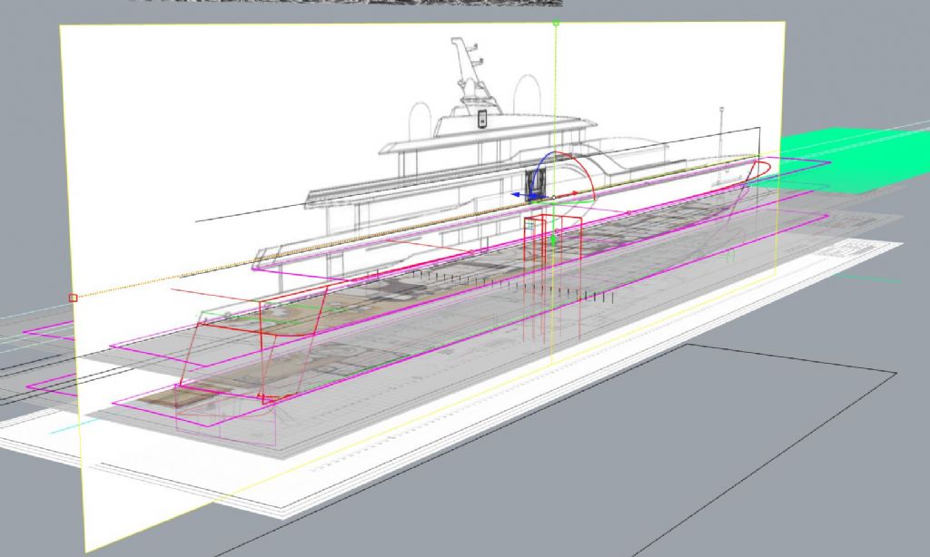
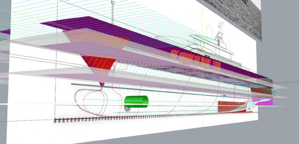
                                  If you have some deck plans and the source of the plans is based in Cad You can get pretty close with photos of the underwater as well.
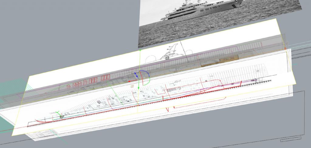
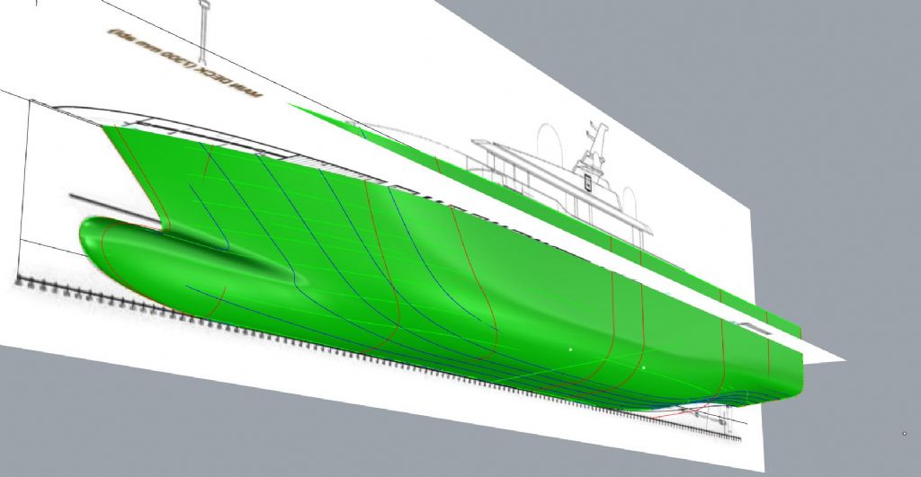
                                  I recently had to build a 3d model of the Super yacht "MY Elements" and had no plans as such but I found deck layout plans of good quality that were from a booking site and by setting those up in a 3d modelling program and fitting the surface to the edges you can get close, its the rise of floor and stern skeg areas that require the photos most of the time.

                                  Here is an example.

                                  https://camperandnicholsons.com/luxury-motor-yacht-for-sale/elements-yachtley-shipyard-turkey-2019

                                  This is where the plans were obtained from.

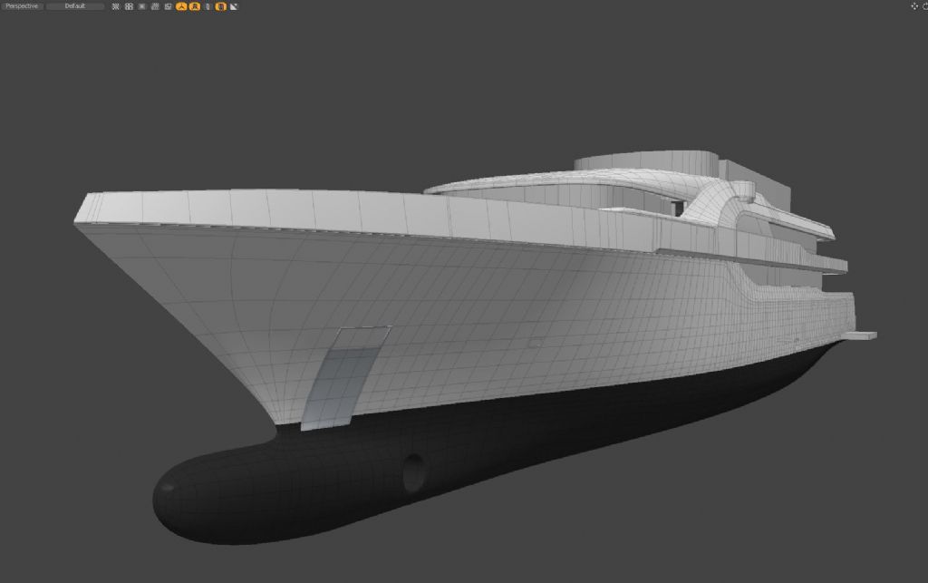
                                  And after setting up the plans at the correct heights and scales the result was this, its close ,not %100 but good enough for the use I needed.
                                  I realize this involves 3d modelling but if you can do that then it is more possible.

                                  setup process looks like this

                                  setup01.jpg

                                  setup02.jpg

                                  setup03.jpg

                                  The red stations are the derived ones from the plans outlines. which then gets surfaced into this

                                  setup04.jpg

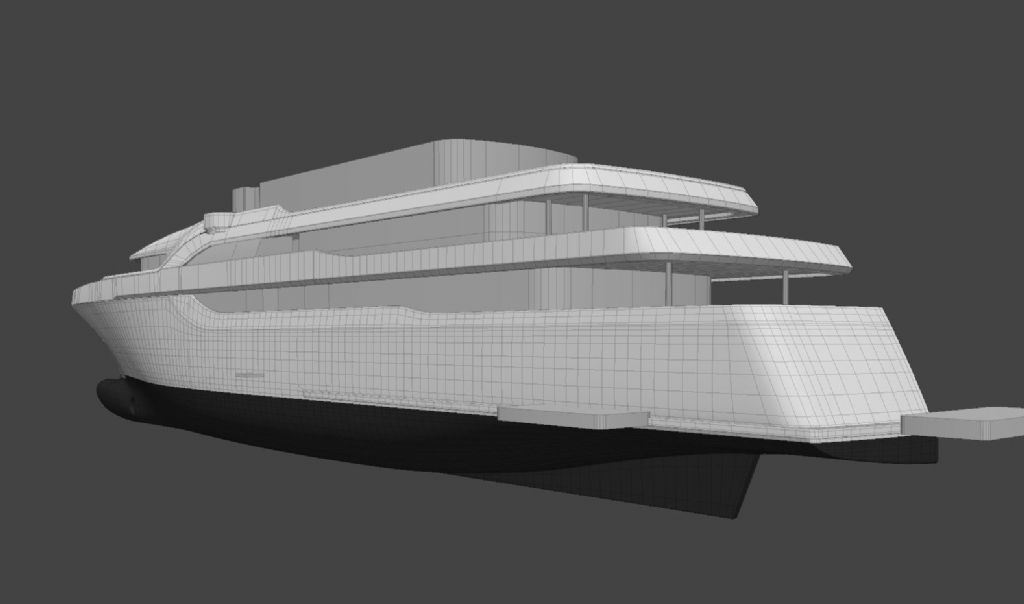
                                  The partially finished result is this..


                                  hull.jpg

                                  hullback.jpg

                                  Edited By Richard H Dunn on 24/05/2021 04:44:39

                                Viewing 15 posts - 1 through 15 (of 15 total)
                                • Please log in to reply to this topic. Registering is free and easy using the links on the menu at the top of this page.

                                Code of conduct | Forum Help/FAQs

                                Advert

                                Latest Replies

                                Home Forums Scratch build Topics

                                Viewing 25 topics - 1 through 25 (of 25 total)
                                Viewing 25 topics - 1 through 25 (of 25 total)

                                View full reply list.

                                Advert