Robbe F14 accessory replacement

Advert

Robbe F14 accessory replacement

Home Forums R/C & Accessories Robbe F14 accessory replacement

  • This topic is empty.
Viewing 8 posts - 1 through 8 (of 8 total)
  • Author
    Posts
  • #68650
    Guido Sambucetti
    Participant
      @guidosambucetti90794

      Hello everybody!

      I have an old F14 Navy radio bought many years ago in preparation for a model -yet to come- that would feature a lot of functional marvels. I also have a Matchbox Flower Class I would like to make RC, adding a mechanism to fire the depth charge throwers. The F14 would be too much for this but it would be better in the Flower than rusting in its box. But I found a problem.

      The said mechanism will be driven by a 1.5v motor. This, in turn, I planned to connect to the Multiswitch Decoder (a device that expands one channel from the receiver into six functions). But I found that I can't wire the motor directly to the Decoder. I need a relay unit. But Robbe is out of business and this product in particular has proved impossible to find.

      Can any of you advise me on finding a replacement? Something easy to connect and use? I don't have the eyesight nor the steady pulse to solder wires into tiny connectors, nor the knowledge to understand the technicla lingo I ran into while trying to find one myself.

      Thank you very much!

      Advert
      #5453
      Guido Sambucetti
      Participant
        @guidosambucetti90794
        #68651
        Tim Cooper
        Participant
          @timcooper90034

          Guido

          Not an expert but I would assume that you would plug a Switcher unit into one of the channels on the Decoder. I have an F14 Navy that does use Robbe relays but only as I didn't know any better. I now have other Radios that operate switchers from a switch on the radio.

          Hope this helps.

          Tim

          #68654
          Dave Milbourn
          Participant
            @davemilbourn48782

            Guido

            These things are possible without Robbe.
            Which model of the decoder do you have? There are five different types, two of which have outputs only for switches while the others have either all proportional outputs or a mixture of each.
            Also can you confirm that you want to drive the motor in both directions and perhaps have limit switches to prevent it over-running at each "end".

            Dave M

            Edited By Dave Milbourn on 13/11/2016 09:15:30

            Edited By Dave Milbourn on 13/11/2016 09:16:13

            #68659
            Guido Sambucetti
            Participant
              @guidosambucetti90794

              Many thanks for both your quick replies!

              Tim: that's what I want to do, but as the Robbe devices are no longer available I need to find a replacement.

              Dave: you're right, surely there's no need for original Robbe parts, but I'm at loss as what to buy, as compatibility issues may arise.

              On the Tx side I've a Multi-Switch Module (3x on-off, 2 fwd-off-rev and one momentary switch). On the receiver side there's a Decoder (F1513). For the specific case of the depth charge throwers I only need the motor to turn in one direction (it will turne two drums much like in a music box, the pins on the drums acting like triggers for sping-loaded pins that in turn will shoot the charges overboard).

              There's no need for end-switches either, as in case of "too much turn" it would simply trigger empty throwers.

              The two-direction turn with end switches sound very intereting too, but that would be for the following project.

              #68664
              Dave Milbourn
              Participant
                @davemilbourn48782

                Guido

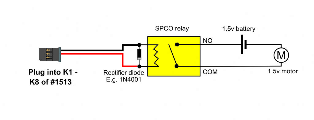
                This circuit will do the job and cost a lot less than anything Robbe ever listed for it. It could be built for a cost of a couple of pounds on a scrap piece of stripboard.

                substitute robbe switch.jpg

                Notes:
                The voltage of the relay coil should be the same as the input voltage to #1513 BATT socket (4.8v – 12v). For example, if you use a 4-cell pack (4.8v) then choose a relay with a 5v coil.
                The relay contacts should be capable of carrying the maximum current drawn under load by the motor.
                Use whichever K socket on #1513 corresponds to the switch on the Tx module which you want to use to operate the motor.

                (If it really was rocket science then I'd be nowhere in sight.)

                Dave M

                #68667
                Guido Sambucetti
                Participant
                  @guidosambucetti90794

                  As simple as that? Really?? Well, I think It's worth the risk of burning my fingers after all!nerd

                  Just a couple of questions, out of sheer ignorance and due not living int he UK (so I can buy the right components): what's the meaning of "SPCO" relay? And I assume the diode code should also be in accordance withe the coil voltage?

                  #68669
                  Dave Milbourn
                  Participant
                    @davemilbourn48782

                    SPCO = Single Pole ChangeOver (It will have two coil pins plus one each Common, Normally Open and Normally Closed contacts)
                    Just fit a 1N4007. It'll block anything to 1000v.

                    DM

                  Viewing 8 posts - 1 through 8 (of 8 total)
                  • Please log in to reply to this topic. Registering is free and easy using the links on the menu at the top of this page.

                  Code of conduct | Forum Help/FAQs

                  Advert

                  Latest Replies

                  Home Forums R/C & Accessories Topics

                  Viewing 25 topics - 1 through 25 (of 25 total)
                  Viewing 25 topics - 1 through 25 (of 25 total)

                  View full reply list.

                  Advert

                  Newsletter Sign-up